HAL Id: hal-00551185
https://hal.archives-ouvertes.fr/hal-00551185
Submitted on 2 Jan 2011
HAL is a multi-disciplinary open access
archive for the deposit and dissemination of
sci-entific research documents, whether they are
pub-lished or not. The documents may come from
teaching and research institutions in France or
abroad, or from public or private research centers.
L’archive ouverte pluridisciplinaire HAL, est
destinée au dépôt et à la diffusion de documents
scientifiques de niveau recherche, publiés ou non,
émanant des établissements d’enseignement et de
recherche français ou étrangers, des laboratoires
publics ou privés.
Stabilisation of Cavitation Zone for Therapeutic
Applications
Alexei Moussatov, Cyril Lafon, Jean-Louis Mestas, Sabrine Chesnais,
Jaqueline Ngo, Lucie Somaglino, Jean-Yves Chapelon
To cite this version:
Alexei Moussatov, Cyril Lafon, Jean-Louis Mestas, Sabrine Chesnais, Jaqueline Ngo, et al..
Stabili-sation of Cavitation Zone for Therapeutic Applications. 10ème Congrès Français d’Acoustique, Apr
2010, Lyon, France. �hal-00551185�
10ème Congrès Français d'Acoustique
Lyon, 12-16 Avril 2010Stabilization of Cavitation Zone for Therapeutic Applications
A. Moussatov, C. Lafon, J.-L. Mestas, S. Chesnais, J. Ngo, L. Somaglino, J.-Y. Chapelon
INSERM, Applications des Ultrasons a la Therapie U556, 151 cours Albert Thomas, 69424 Lyon Cedex 03, FranceCavitating bubbles in the focal area of a focused ultrasonic beam form a zone of cavitation. One can observe fluctuations of the zone in terms of its size and position around focal point. Complex distribution of acoustic pressure, radiation force and streaming determine bubble cloud formation. The cloud modifies the ultrasonic field distribution. That explains fluctuations of size and position of the cavitation zone relative to ultrasonic source. For therapeutic applications of cavitation such instability in space and in time is often problematic as the treatment cannot be controlled spatially and the “cavitation dose” cannot be quantified. The authors propose a practical and simple solution by mixing several ultrasonic beams. A smaller cavitation zone is achieved compared to a single focused beam. Fluctuations are significantly reduced. Bubble activity is illustrated by in-vitro experiments with ultrasonic imaging. Bioeffects of different exposure conditions are evaluated in-vivo on subcutaneous tumors on rats. Histological analysis shows that a necrotic zone caused by cavitation is as it is expected. This EUREKA labeled project (E! 4056 UMDD) is supported by the Franco-Norwegian Foundation (convention FNS 07-01) and OSEO (A0712014V).
1 Introduction
Ultrasound is routinely used for diagnostic applications, either per se or in combination with ultrasound contrast agents. In recent years, research interests in biomedical ultrasonics have been gradually shifted from pure diagnostic imaging towards therapeutic uses of ultrasound energy. Therapeutic ultrasound is known to induce several effects in tissue [1]. Thermal effects are used in clinics by high intensity focused ultrasound (HIFU) to heat tumor tissue above 65 deg C and thus destroy cancer cells [2].
Cavitation is an important phenomenon in many areas of science and engineering, including acoustics, chemistry, hydraulics and medicine. Cavitation has been shown [1] to play a key role in a wide range of novel therapeutic applications of ultrasound. Recently a new concept of therapeutic ultrasound combined with genes and drugs has attracted a particular interest. The major physical action for the intended surgical effect is mainly mechanical and is induced by cavitation [3].
Optimization of ultrasound technology and dosimetry is needed in order to localize and better control cavitation.
The present work deals with focused therapeutic-range ultrasound and concerns improvement of cavitation spot stability required by numerous biomedical applications.
2 Frontiers
of
Technology
2.1 Cancer Statistics
One third of the total population within the Western world will develop cancer. Of these about 50 % will die from the disease within five years after being diagnosed. About 20% of all cancer deaths are due to failure in local treatment of tumors.
2.2 Therapy Limitations
A serious limitation of conventional chemotherapy is the unspecific distribution of cytotoxic drugs resulting in reduced therapeutic efficacy and systemic side effects. In contrast, cytotoxic drugs formulated as nanoparticulate or liposomal delivery systems favor accumulation in solid tumors (several liposomal cytotoxic drugs are already commercially available like liposomal Doxorubicin Caelyx®). There are, however, still disadvantages associated
with such liposome products: drug release from the liposome carrier is slow, tumor cell uptake is not improved, and the therapeutic-to-toxicity ratio is in general borderline. Various approaches have been investigated to target drug delivery via triggered release, e.g. by hyperthermia, enzymatic and pH mediated strategies.
2.3 Ultrasound Mediated Drug Release
A promising approach is to combine ultrasound with ultrasound responsive drug carriers, e.g. sonosensitive liposomes. Focused ultrasound is applied to the target (tumor) tissue resulting in both enhanced release of drug from the carrier and concomitant increased drug uptake into tumor tissue as well as tumor cells.
Schematic presentation of ultrasound induced drug release in tumour.
Application of ultrasound to facilitate drug delivery has become a research area of increasing interest [4,5]. Conventional liposomes can, if properly designed and triggered by optimized ultrasound devices, efficiently release their drug payload upon exposure to ultrasound in tumor tissue. This treatment will result in the delivery of higher concentrations of the drug, in a limited and well-defined area minimizing unwanted systemic toxic effects. The improved therapy may represent a new alternative within cancer treatment.
3 Results
and
Discussion
3.1 Single Transducer Setup
A single focused ultrasonic transducer is commonly used when a limited zone of cavitating media has to be created at a certain distance away from transducer. It also allows for amplification of ultrasonic beam due to geometrical convergence. The transducer can conveniently be coupled with an ultrasonic scanner to facilitate visualization and guide cavitation activity (Fig. 1).
Figure 1 : Typical use of single focused transducer Advanced ultrasound device has been developed. The purpose of this device is to generate an ultrasound field inducing cavitation to release drug from liposomes. The device is combined with a real-time imaging probe in order to position and monitor the treatment. The ultrasound probe design is based on the EDAP’s Ablatherm High Intensity Focused Ultrasound technology. The probe was modified to meet the particular needs and was manufactured by EDAP (Fig. 2).
Figure 2 : EDAP Ablatherm HIFU technology
It embeds a high power piezocomposite ultrasound therapy transducer with matching layer, nominal frequency 1 MHz, F=45mm, 4 independent sectors connected in parallel with total 56.9x34.6 mm² active surface; Imaging transducer concentric with therapy transducer; Vermon 5Mhz sectorial probe; B&K Scanner; 2.4x1.25x12 mm focal spot on -6dB contour; focusing gain G=190.
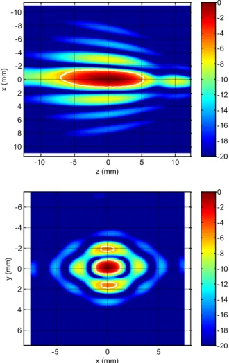
The transducer was characterized with standard acoustic tests. The electro-acoustic efficiency is greater than 70% (between 70% and 80%) for emissions at 1 MHz with acoustic intensities up to 15 W/cm² at the surface of the transducer. Shape of acoustic field in the vicinity of the focus is represented by Fig. 3.
z (mm) x ( m m ) -10 -5 0 5 10 -10 -8 -6 -4 -2 0 2 4 6 8 10 -20 -18 -16 -14 -12 -10 -8 -6 -4 -2 0 x (mm) y ( m m ) -5 0 5 -6 -4 -2 0 2 4 6 -20 -18 -16 -14 -12 -10 -8 -6 -4 -2 0
Figure 3 : Ultrasonic transducer field in the focal region According to the feasibility evaluation, the experiments prove that strong inertial cavitation can be obtained in vivo around the focal point with this probe, and a sufficient dose of treatment can be applied to the target.
In order to enhance cavitation while reducing heat deposition in the target, pulsed wave ultrasound emission is proposed. The driving signal for the power transducer is supplied by a sinus generator in burst mode amplified by a radiofrequency amplifier. The acoustical power emitted by the transducer is assessed by the electrical power measured by a wattmeter, knowing the electro-acoustic efficiency.
The probe was placed in degassed water and the therapeutic transducer was excited by high intensity sine bursts (repetition frequency 200 Hz, duty cycle 5%, sinus frequency 1 MHz) in order to induce cavitation in water. For this driving regime, cavitation threshold was reached at
5W emitted acoustical power (averaged in time over the bursts). The power amplifier allowed 4 times increase in radiated power from the threshold level before its electronic circuit was saturated (output voltage limitation), that corresponds to 20 W for described regime.
3.2 Problems with Single Transducer Operations
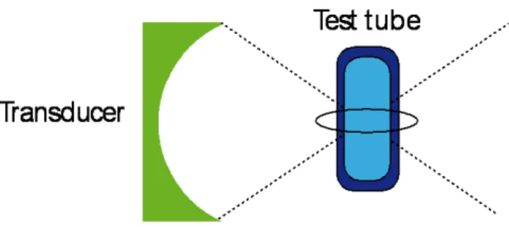
In-vitro experiments were performed either on pigs liver tissue or on a polyethylene test tube with 3 ml volume for a target liquid, as shown on Fig. 4. Transducer focal area was superposed upon the target, then ultrasonic irradiation was activated. A wide range of driving sonication regimes was implemented in order to optimize cavitation activity. Duty circle, burst repetition rate, burst forme and duration as well as signal amplitude were largely changed. Achieved cavitation activity was strong enough to be used for in-vivo study.
Figure 4 : In-vitro setup with a test tube
However, common problem was noticed with location of the zone where cavitation activity was manifested. The problem was clearly identified with help of a test tube (diam. 12mm, 30 mm long) containing inside the same liquid than outside, i.e. degassed water. Cavitation appeared and spontaneously moved along geometrical axis of the ultrasonic beam. At one moments, it was observed inside the tube at focal point, at other moments it was attached to the test tube wall from outside. There was no way to keep cavitation zone only inside the tube. Re-appearance of the cavitation outside the tube was regular and uncontrollable.
The problem has been identified as the problem of stability or location of cavitation zone. It can be summarized as following:
* Impossible to maintain cavitation in desired location (focal point)
* Cavitation zone moves spontaneously forward and backward from focal point along ultrasonic beam
* Cavitation activity in focal point suddenly jumps up-and-down
In terms of in-vivo applications for cancer treatment, this problem will lead to the next difficulties:
# treatment of cancers larger than a focal spot by sweeping cavitation zone over cancer volume is not feasible
# undesirable exposure of surrounding tissue to cavitation (security)
# necessity to use “Index of Cavitation” in order to control delivered dose of cavitation treatment
A practical solution was needed to cope with this problem.
3.3 Dual Confocal Transducer Configuration
Dual-beam pulse ultrasonic irradiation has been known to significantly improve cavitation activity for sonochemical applications. For example, mixing two orthogonal ultrasonic beams of the same plain transducers of 1 MHz produces the cavitation yield of three times the sum of the yield of two single ultrasonic irradiations [6].
Extending dual-beam concept to superposition of two focused ultrasonic beams may give a double advantage: the first in terms of cavitation activity enforcement, and the second in terms of reduction of the cavitation zone.
To resolve the above-mentioned problems, the authors have proposed the confocal transducer configuration that is schematically outlined on Fig. 5.
Figure 5 : Confocal Transducer Configuration
Two focused therapeutic transducers are placed orthogonally with their respective focal points being superposed. Taking into account cigar-like shape of the focal zone and its length that exceeds its diameter for at least five times, the cross-section of both focal zones is much smaller in volume than each of the zones. When working in the proximity of cavitation threshold amplitudes, it is feasible to get over this threshold only within the tiny area of the crossing of both focal zones.
Thus, appearance of cavitation is possible only within a spot of 2mm x 2mm x 2mm that is fixed relative to ultrasonic transducers. High stability of this spot with cavitation is expected.
3.4Confocal Transducer Performance
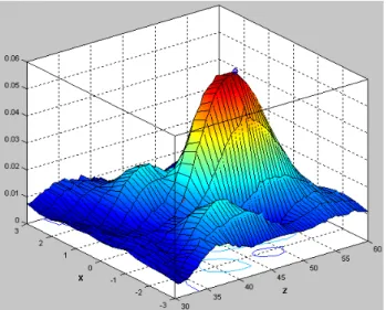
Acoustic pressure diagram for the second ultrasonic transducer is shown on Fig. 6. Second transducer is similar to the first one but much simpler. It has airbacked 50 mm diameter piezoceramic 1 MHz element focused at F=50mm, focal spot 2x2x13 mm at -6 dB. It does not keep any imaging parts.
Figure 6 : Pressure diagram for the second ultrasonic transducer around focal point
Figure 7 : Acoustic module of experimental setup.
Transducers are placed at 90 degrees in a water tank; Zoom on confocal transducers during ultrasonic irradiation
in degassed water
Tests performed at ultrasonic driving parameters described above at different amplitude of irradiation confirmed expectations for cavitation zone stabilization. Reduced cavitation spot can be seen on Fig. 7 (zoom on working transducers, between them). It corresponds to 2mm x 2mm x 2mm crossection volume. Its position is highly stable relative to transducer emitting surfaces.
By Confocal Transducers Concept following practical difficulties have been resolved :
1. Uncontrolled manifestation of cavitation activity outside desired location
2. Spontaneous variations in cavitation activity in focal point
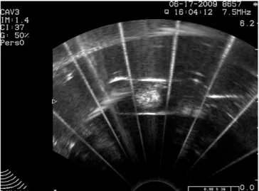
Figure 8 : Ultrasonic scanner imaging of stabilized cavitation zone for weak and for strong irradiation power.
Clear visualization of obtained cavitation spot by means of ultrasonic scanner is illustrated on Fig. 8. Cavitation zone comes up as bright circle in the center of scans that are made in the plain containing both ultrasonic beams, one is running in vertical, the other in horizontal direction. Circle diameter increases with irradiation power. Its position on the scanner screen does not change in time.
Critical experiment was performed with the test tube. Finally it was possible to keep cavitation entirely inside the tube as long as necessary. No cavitation happened outside
the tube or on its walls when the beam crossection was put in the middle of the tube. Thus, perfect control over the cavitation zone has been successfully achieved. Fig. 9 illustrates enclosure of the zone within the test tube by M-Scan image. Technical performance of improved confocal transducer configuration can be summarized :
Highly localized zone of cavitation Remarkable stability of cavitation activity Well controlled cavitation within desired
location
Security aspect: Practical solution to avoid cavitation outside desired location
In-vivo performance of described confocal transducer setup on rats with subcutaneously implanted Dunning tumors will be reported elsewhere.
Figure 9 : B-Scan and M-Scan images of localized cavitation within test tube
4 Conclusion
By applying confocal transducers configuration, an instability of cavitation activity within focal area has been significantly reduced:
Spatial oscillations of cavitation spot along ultrasonic beam have been eliminated.
Zone of cavitation has been limited to the size of focal aperture.
Cavitation activity within the zone has been enhanced by dual beam irradiation.
Fluctuations of cavitation have been reduced. Well controlled cavitation spot has been achieved on the cross-section of the ultrasonic beams. It has permitted to cavitate only at the required point and avoid manifestation of cavitation bubbles outside desired location.
Ultrasonic imaging system has been successfully combined with confocal transducers. It has permitted on-line monitoring of cavitation bubbles during vitro and in-vivo tests.
Stabilization of cavitation zone has allowed application of continuous sweeping of tissue during in-vivo cancer treatment on animal model without increased risk to side effects due to overdose on some parts of treated tissue.
Improved cancer treatment concerns technology to deliver approved and established cancer drugs exactly where they are needed by means of ultrasound mediated release from drug carriers. This approach provides increased quality of life and prolonged life expectancy for patients, thus even small therapeutic gains contribute to the high medical need.
Acknowledgements
This work is a part of EUREKA labeled project (E! 4056 UMDD), and has been supported by the Franco-Norwegian Foundation (convention FNS 07-01) and OSEO (A0712014V).
References
[1] Bailey M.R., Khokhlova V.A., Sapozhnikov O.A., Kargl S.G., Crum L.A. "Physical Mechanisms of the Therapeutic Effect of Ultrasound (A Review)",
Acoustical Physics, Vol.49, No.4, 369-388 (2003).
[2] Kennedy JE. High-intensity focused ultrasound in the treatment of solid tumors. Nat. Rev. Cancer, 5, 321 (2005).
[3] Dalecki D. "Mechanical Bioeffects of Ultrasound",
Annu. Rev. Biomed. Eng., 6, 229-248 (2004).
[4] Pitt WG, Husseini GA, Staples BJ: Ultrasonic drug delivery - a general review. Expert. Opin. Drug
Deliv., 1, 37 (2004)
[5] Larina IV, Evers BM, et al. Enhancement of drug delivery in tumors by using interaction of nanoparticles with ultrasound radiation. Technol.
Cancer Res. Treat., 4, 217 (2005)
[6] Feng R., Zhao Y., Zhu C., Mason T.J. "Enhancement of ultrasonic cavitation yield by multi-frequency sonication", Ultrasonics Sonochemistry, 9, 231-236 (2002).