Publisher’s version / Version de l'éditeur:
ASTM Bulletin, 229, pp. 67-72, 1958-06-01
READ THESE TERMS AND CONDITIONS CAREFULLY BEFORE USING THIS WEBSITE.
https://nrc-publications.canada.ca/eng/copyright
Vous avez des questions? Nous pouvons vous aider. Pour communiquer directement avec un auteur, consultez la
première page de la revue dans laquelle son article a été publié afin de trouver ses coordonnées. Si vous n’arrivez pas à les repérer, communiquez avec nous à [email protected].
Questions? Contact the NRC Publications Archive team at
[email protected]. If you wish to email the authors directly, please see the first page of the publication for their contact information.
NRC Publications Archive
Archives des publications du CNRC
This publication could be one of several versions: author’s original, accepted manuscript or the publisher’s version. / La version de cette publication peut être l’une des suivantes : la version prépublication de l’auteur, la version acceptée du manuscrit ou la version de l’éditeur.
Access and use of this website and the material on it are subject to the Terms and Conditions set forth at
Methods for rating concrete waterproofing materials
Kocataskin, F.; Swenson, E. G.
https://publications-cnrc.canada.ca/fra/droits
L’accès à ce site Web et l’utilisation de son contenu sont assujettis aux conditions présentées dans le site LISEZ CES CONDITIONS ATTENTIVEMENT AVANT D’UTILISER CE SITE WEB.
NRC Publications Record / Notice d'Archives des publications de CNRC:
https://nrc-publications.canada.ca/eng/view/object/?id=c52e1cce-d16f-4de8-b9d0-817dc4ccee08
https://publications-cnrc.canada.ca/fra/voir/objet/?id=c52e1cce-d16f-4de8-b9d0-817dc4ccee08
Ser
TH1
N2lr2
no.
58
c . 2
NATIONAL
RESEARCH
COUNCIL
4 ' f 4 ~
yzeD
CANADA
DIVISION OF BUILDING RESEARCH
METHODS FOR
RATING CONCRETE WATERPROOFING MATERIALS
BY
F. KOCATASKlN AND
E.
G.
SWENSON
REPRINTED FROM A. S. T. M. BULLETIN NO. 229 APRIL 1958, P . 6 7
-
72RESEARCH PAPER NO. 5 8
O F T H E o
DIVISION OF BUILDING RESEARCH
BUILDING
RESEARCH
OTTAWA
JUNE
1958
NATIONAL RESEARCH COUNCIL
This p u b l i c a t i o n
i s
b e i n g d i s t r i b u t e d by
t h e D i v i s i o n of B u i l d i n g Research of t h e N a t i o n a l
Research Council a s
a c o n t r i b u t i o n towards b e t t e r
b u i l d i n g i n Canada.
I t should n o t be reproduced
i n whole o r i n p a r t , w i t h o u t permission o f t h e o r i -
g i n a l p u b l i s h e r .
The D i v i s i o n would be g l a d t o be
of a s s i s t a n c e i n o b t a i n i n p such permission.
P u b l i c a t i o n s of t h e D i v i s i o n of B u t l d i n g
Research
may be o b t a i n e d
by
m a i l i n g t h e a p p r o p r i a t e
r e m i t t a n c e ,
( a
3aiik, Lupress, o r Post Off i c e Money
Order o r a cheque
nade
payable a t p a r i n Ottawa,
t o t h e Receiver G e n e r a l of Canada, c r e d i t N a t i o n a l
R e s e a r c h c o u n c i l ) t o t,he K a t i o r ~ l
Research C o u n c i l ,
Ottawa.
. ? t m , p a r e n o t acceytabl-e
.
A
coupon system
h a s
been in,troduced t o
make payments f
01-p u b l i c a t i o n s r e l a t i v e l y simple,
Coupons a r e a v a i l a b l e i n denominations of
5,
25,
and
50
c e n t s ,
and may be o b t a i n e d by
making
a r e -
m i t t a n c e
as
i n d i c a t e d above.
These coupons
may be
used
f o r t h e purchase
of
a l l N a t i o n a l Research
C o u n c i l p u b l i c a t i o n s i n c l u d i n g s p e c i f i c a t i o n s
of
t h e Canadian Government S p e c i f i c a t ions Board.
M e t h o d s for Ratins Concrete Waterproofins Materials
b y F. K O C A T A S K I N and E. G. S W E N S O N
In an attempt to develop reliable test methods for evaluating the effectiveness of concrete waterproofers, it was found that a combination of saturated and un- saturated permeability tests is necessary, the latter covering more than one hu- midity condition
Tm
usE op ~vaterproof- ing admixtures or surface treatments for mortars and concrete has become wide- spread in recent years. Although the benefits to be derived from their use are questioned by many concrete experts, there has been no serious attempt to develop separate methods for rating the effectiveness of these materials for each of the various conditions that can exist in the field.Waterproofing admixtures or surface treatments have been mainly associated with prevention of liquid flow through concrete. The prevention of dampness and the stopping of rain penetration are also claimed for many materials. Of added interest is the possible effect of such agents in reducing efflorescence, staining, and frost damage on exposed mortar or concrete.
The problems involved in properly evaluating these materials concern:
(a) the various types of moisture situa- tions; ( b ) the various types of water- proofing materials on the market;
( c ) the variation in the constituents and composition of the concrete; (d) the reactions of waterproofing materials with different cements; and ( e ) the in- fluence of waterproofing materials on other ~ r o ~ e r t i e s of the concrete. such as , -
strenit11 a n d durability. Comprehen- sive investigations with integral or sur- face waterproofing materinls involve
-
NOTE.-DISCUSSION O F TI-IIS PAPEIt IS INVITED, elther for publication or for the attention of the authors. Atltlrcss all communications to ASTM Heatlquarters, 1916 Race St., Philadelphia 3, Pa.
'
The boldface numbers in parentheses rc- fer to the list of references appe~lclecl to this paper.mainly tests with water pressure and absorption (1,2,3,4,5,6).l But the de- velopment of a reliable test procedure involving all possible problems has not appeared in the literature. The pres- ent investigation was therefore under- taken to serve as a basis for the estab- lishment of a simple but satisfactory series of test methods.
Initial Considerations
Structure of Concrete and Nature of Moisture Flow
Hardened concrete is a solid contain-
ing a gel pore system, a n aggregate pore system, both usually very fine, and a cement-paste pore system t h a t varies with water-cement ratio, degree of com- paction, degree of hydration, and type of cement. Aggregate pores and gel pores play only a minor role in the trans- port of moisture. The cement paste pores are scattered capillary pockets and channels, some isolated, some inter- connected. Their size varies from very fine to very large. They are responsible for the degree of permeability of con- crete (7,8).
FERRUH K O C A T A S K I N , research engineer, Istanbul American College, i s a graduate of the Technical University of Istanbul where he was assistant professor in civil engineering. The pre- sent paper i s the result of work done as a Postdoctorate Fellow of the National Research Council of Canada in 1955-56.
E. G. S W E N S O N , associate research officer, Materials Sec- tion, Division of Building Research, National Research Council of Canada, and formerly assistant professor i n chemistry at the University of Saskachewan, i s currently in charge of cement and concrete research and the author of several papers in this field.
April 1958
A S T M B U L L E T I N
(TP 85)
67Authorized Reprint from the Copyrighted ASTM BULLETIN No. 229, April, 1958 American Society for Testing Materials, Philadelphia 3, Pa.
Under isothermal conditions water may be tr~ssferred through this porous system by Gapor &m for low moisture contents and by liquid ffo~v for saturated conditions. For partially saturated conditions both mechanisms are be- lieved to operate simultaneously.
Under nonisothermal conditions these situations may be complicated by the in- fluence of temperature gradients be- tween different parts of the concrete. They may be further complicated by osmotic pressures or electrical poten- tials. I n the present study, however, these aclditional effects as well as other accidental means for water transfer through concrete, such as cracks, honey- combing, and joints, will not be taken into consideration.
Theory of Moisture Flow
The theory of moisture flow in porous media has been developed in analogy with heat transfer (9,10,ll).
It
uses the concept of potential and the general equation of flow is given for the one dimensional case as:where:
0 = the moisture content a t point
x,
a t the time t,= the moisture potential a t point
x,
a t the time 1, and I<(+) = the permeability function. The potential $ represents the specific free energy of the moisture. For prac- tical application it may be expressed either in terms of hyclraulic pressure Por in terms of vapor pressure p, as con- venience demands.
A direct solution of the general flow equation is not possible, and it is neces- sary to determine experimentally the function
K ( $ ) ,
relating pernleability to moisture potential.I n the case of steady-state flow, the general equation is simplified, can be in- tegrated once, and takes the form:
For the saturated steady-state flow this is the well-known DarcyJs formula:
For the unsaturated steady-state flow, and regarding vapor pressure as the potential:
-
2 Tentative hfetl~od of Test for Co~npressive
Strength of Hydraulic Cement Mortars (Us- ing Portions of Prisms Broken in Flexure) (C 349-54 T ) , 1955 Book of ASTM Standards, Part 3, p. 136. iV1ethod of Test for Tensile Strength of Hydraulic Cement Mortars (C 190-49), 1955 Book of ASTM Standards, Part 3, p. 188.
6 8
(TP
86)I n the case of transient flow only simple problems like capillary absorp- tion or drying by evaporation can be solved with certain assumptions. For capillary absorption, for instance, as- suming:
where:
-y = density of water,
a = porosity of the medium, and f = suction force,
the equation may be integrated and the well-known capillarity formula ob- tained:
The coefficient Ii,, known as the capil- larity-coefficient, is a function of the porosity, permeability, and suction of the nledium. Therefore it is not a constant; it depends upon the initial moisture condition of the medium.
These considerations show that the effects of material properties upon mois- ture flow may be reflected through the coefficients I i , Ii(p), and Ii,. For cor- rect evaluation of integral or surface waterproofing materials on the basis of their effectiveness in decreasing the flow of moisture in concrete, it is necessary to study their influence on these coefli- cients for the whole range of the varia- tion of the latter. The usual hydro- static flow test or the simple absorption test would appear to be insufficient.
It
is clear that proper evaluation can be achieved only by a series of tests to cover the various situations that can occur.Selection of Waterproofing Materials and Preparation of Test Specimens
From commercially available groups, four integral and three surface water- proofing materials were selected as repre- sentative :
Admixture l-Accelel.ator type (calcium chloride solution).
Admixture 2-Water-repellent type (am- monium stearate paste).
Admixture 3-Bituminous emulsion. Admisture 4-A paste of siliceous and or-
ganic composition.
Surface waterproofing material l-Cement grout (water-cement ratio, 0.75). Surlace waterproofing material 2-Cement
base paint (water-paint ratio, 0.75). Surface waterproofing material 3-Silicone
resin solution (5 per cent silicone). A type I Canadian cement was used.
It is referred to as cement
X.
A S T M B U L L E T I N
Two mortar conlpositions were sa-
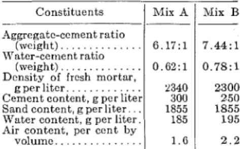
lectecl: mortar A was fairly rich and with a low water content; mortar B \vas a lean mix with a high water content. The sand used was one which has a good service record. I t s specific gravity in the saturated surface-dry condition was 2.6. Separate sieve sizes were blended to give the following percentages passing each sieve size (the latter in parenthe- ses: 100 per cent (No. 4), 80 per cent (No. S), 60 per cent (No. 16), 35 per cent (No. 30), 15 per cent (No. 5), 5 per cent (No. loo), and 0 per cent (pan). Table I gives the proportions of the mixes as used in the test specimens.
TABLE 1.-hIIS PROPORTIONS USED I N TEST SAB/IPLES. Mix B 7 . 4 4 : l 0 . 7 8 : 1 2300 250 1855 195 2 . 2 Constituents Aggregatc-cement ratio (weight). . . Water-cement ratio (weight). . .
Density of fresh mortar, g per liter. . .
Cement content, g per liter . . Sand content, g per liter. Water content, g per liter. Air content, per cent by
. . . volume..
Preparation of test specimens was as follows:
(a) Specimens With Integral Water- proofing Materials.-Small cylindrical specimens 4 in. in diameter and 1 in. thick were made from these mixes, with ancl without each of the selected admix- tures. Additional specimens were made for supplementary tests for conlpressive strength, tensile strength ancl shrinkage, according to ASTi\lI standards."ll specinlens mere cured in near 100 per cent relative humidity conditions a t 23 C, demolded, stored in water for
G clays, then placed in a room condi- tioned a t 50 per cent relative humidity and 23 C to the age of 28 days. Identifi- cation of the specinlens was provided by a code, the first letter referring to the mortar, the number t o the admixture, and the third letter to the cement, for example AOX, A l X , etc. \mere the middle term is zero no admixture was used. Duplicate specimens mere used for each test and their mean values are reported throughout.
(b) Specimens With Surface Water- proofing Materials.-All surface water- proofers are intended t o be painted on surfaces with smooth textures and with- out large pores. Since mortar A met these requirements, it was used in these tests. The size, shape, preparation, ancl curing of the specimens were the same as for the series containing integral waterproofing materials. Surface wa- terproofings were applied a t the age of
Mix A 6 . 1 7 : 1 0.62: 1 2340 300 1855 185 1 . 6
28 days on one face of the specimens. After this the specimens were cured an additional 14 days a t 50 per cent rela- tive humidity before tests mere started. For identification, a letter-number code was used, the letter indicating surface, the number referring to the water- proofer, for example, SO, 81, S2, etc. The case of SO means that 110 water-
proofer was applied.
Experiments and Results
Specimens with Materials
Integral Waterproofing
The Unsutu~ated Pe~meability Test.-
In this investigation unsaturated per- meability refers to the case where nlois- ture flow occurs as the result of an ap- preciable vapor pressure gradient in the material. The degree of unsaturation moulcl naturally be different for differ- ent conditions of test. The usual dry-cup procedure for measuring the vapor permeance of building materials (12,13) was found suitable for measuring unsaturated permeability and was adopted with slight lnodification to ac- commodate the relatively thick speci- mens. The specimens mere mounted on aluminum dishes, which were filled ~ ~ i t l l a desiccant (calcium chloride) and the sides sealed with wax. These dry cups mere stored in chambers in con- trolled constant temperature and con- stant liunlidity conditions. Owing to the difference of vapor pressures outside (p) and inside (p, = O), moisture cliffused through the pores of tlie mounted specimens into the clisli mid was taken up by the desiccant. At steady- state conditions the rate of moisture flow, q, mas determined from tlie weight gains of the dish. I t may be noted that by storing several clry cups in different humidity conditions p, corresponding values of q could be determined.
The law of vapor permeability pre- viously given as
qdz = K ( p ) d p
can be expressed, with q = constant for the steady-state flow, as
But it is not possible to carry out the in- tegration without knowing the function li(p). I-Iowever, as i t was possible to obtain values of q for given values of p experimentally by the dry-cup test, these experimental values of q, if multi- plied by 2, plotted against p, and con-
nected by a smooth curve would repre- sent the fop K ( p ) d p function. By
graphical iifferentiation, it is possible then to derive the unlmown permea- bility function K ( p ) .
April
1958
To determine the influence of admix- tures on the unsaturated permeability of concrete, duplicate specimens from all control and test series mere tested by the dry-cup method a t 50, SO, and 100 per cent relative humidities. Figure 1 shows the permeability functions ob- tained by the graphical difierentiation method from results of these tests. As seen from Fig. 1, admixtures 1 and 4
0 -
-
+ 8 , 1 5 Urn h V I-
L = a d a:i
l o E & ci a x L 5X
s
V a ~ o r Pressure 0 ~ u i s l d e , p , g per sq crn Correspandlng R H , -0 50 80 100 Outs~de, p, g per sq c m - Correspandlng R H . -0 50 80 100 per centFig. 1.-Vapor permeabilities of mix A, with and without admixtures.
NOTE.-11 in first graph refers t o the rich mix with low water c c ~ n e n t ratio. B in second graph refers t o t h e lean mix with high water-cement ratio. T h e middle n u ~ n h e r s refer to the admixtures, the zrro term indi- eatlng no adinixture (reference). T h e last term, S , refers t o the ceincnt used.
were not effective; they increased the permeability. Admixture 2 mas effec- tive in one mix, and admixture 3 in both mixes. I n this and the following graphs the data points are not shown for any of the curves since the results are based on proprietary materials the exact com- positions of v-hich are not known. The curves should therefore be interpreted in a qualitative way. For this reason also much of the data is not included in this paper.
A special case of unsaturated per- meability will be obtained when a con- crete is subjected to liquid water on one surface and to free air on the other sur- face. Dense concretes with their ex- tremely fine pores offer such a great re- sistance to liquid flow that the concrete will dry out by evaporation to the air
A S T M B U L L E T I N
and a condition of partly saturated and partly unsaturated permeability will occur (14). The flow will be influenced by both the coeficients of saturated and ulisaturated permeabilities. As results of investigations show, however, most integral waterproofing materials have no appreciable effect on the first coeffi- cient (saturated permeability). There- fore, the function of the second coeffi- cient K(p) (unsaturated permeability) is also expected to reflect the effects of integral waterproofing materials for this special case of composite permeability. Experimental eviclence mas provided by a series of so-called inverted met-cup tests, in n hich specimens of each series were mounted on aluminum dishes, as for the vapor permeability test. The dishes were filled ~vith 1 to 2 in. of water, the sides sealed nit11 wax and the dishes inverted, bringing the water to tlie top of the specimens. Pairs of these in- verted wet cups mere stored in still air a t 50 per cent relative humidity, leaving their bottom surfaces free for evapora- tion. After steady-state conditions were reached, rates of moisture flow were determined from weight losses of the clislies. The results, not recorded here, were closely similar to those on Fig. 1 on vapor permeability.
The Sntz~mled Perrneabilit?l Test.-
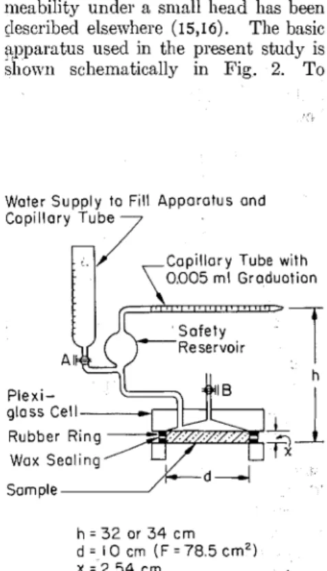
I11 this study saturated permeability
refers to the case where moisture flow occurs as the result of a hydrostatic pressure gradient in a specimen in which the degree of saturation is determined by the condition of test. Apparatus suitable for determining saturated per- meability under a sniall head has been &scribed elsewhere (15,16). The basic y ~ p a r a t u s used in the present study is slio~vn schematically in Pig. 2. To
Water Supply to Fill Apporotus ond Capillary Tube
7
Copillory Tube with r 0 . 0 0 5 rnl Groduotion piexi-
33+.
glass Cell Rubber Ring-
Wox Sealing h = 3 2 or 3 4 c m d = 1 0 cm ( F = 7 8 5 c m Z ) x = 2.54 crnFig. 2.-Saturated permeability apparatus.
avoid the complications introduced by evaporation a t the exposed face, the apparatus was stored in a room con- trolled a t near 100 per cent relative humidity and 23 C. The apparatus was designed to maintain a constant hydraulic head on the specimen by means of a horizontal capillary tube, and to allow measurement of flow into the specimen through observation of the miniscus in the capillary tube. Measurements were begun when drop- lets became visible a t the exposed sur- faces and were taken each day for one week.
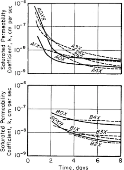
Experimental results show that if the conditions producing flow are main- tained over a substantial period, there is a continuous decrease in the per- meability of the concrete. Explana- tions have been given in terms of ex- pansion of cement particles due to fur- ther hydration, swelling of the cement and aggregate colloids due to wetting, clogging of the pores by products of the chemical combination of bicarbonates in water with the free lime of cement, re- tardation of flow due to the establish- ment of an electrical potential, retarda- tion of flow due to osmotic pressures, etc. For practical purposes, it seemed sufficient to follow this change in per- meability up to seven days, a t which time it became practically constant.
Duplicate specimens from all control and test series were tested for saturated permeability under the conditions de- scribed above. The permeability coef- ficients calculated from the rates of flow using Darcyls formula are plotted in
Fig. 3 against time, using semilogarith- mic coordinates for convenience. Be- fore comparing the results obtained from test series with those obtained from con- trol specimens, it was necessary to know how much variation was to be expected between specimens of the same compo- sition, but prepared from different batches. Therefore, additional dupli- cate specimens were prepared from additional batches of mixes AOX (rich mix) and BOX (lean mix), and these were tested for permeability in the same manner. The results of these additional series are shown in Fig. 3 as curves AOXR and BOXR. (These batches of the same composition were carried out to check reproducibility.)
Comparing the results, it is seen that permeabilities from all test series fall within the range of their control mixes. Thus none of the admixtures has shown any markedly beneficial properties. This result is in essential agreement with the conclusions reached by other investi- gators.
The Capillary Absorption Test.-No special apparatus was needed for this test. The specimens were stored until
70
(TP
88)
equilibrium was reached a t 50 per cent relative humidity and then weighed and set in contact with water from one sur- face. The amount of absorption was measured by taking weights a t intervals. The square of the weight gain was plot- ted against time to give straight lines of the form :
It
was assumed that a represented the first amount of water necessary to wet the surface. The slopes,Ii,,
of these straight lines were determined. The same procedure was repeated for 0 per cent relative humidity equilibrium conditions. The values ofIi,
obtained for 0 per cent and 50 per cent equilib- rium relative humidity conditions are plotted in Fig. 4. I t was possible to draw a suitable curve through these two points and through theIi,
= 0 point a t 100 per cent relative humidity, as- suming the same general shape as given for absorption isothernls of porous ma-U 2 % .-
-
L .- 0 0g
5
a";
u-
w-
w c 0 'yj 3 z-
L 0 w m 0 0 0 2 4 6 8 Time, daysFig. 3.-Saturated permeabilities of mixes A and B, with and without admixture.
terials, and thus obtain the whole variation of the capillarity coefficient. The thickness of the specimens was shown to influence the results of the capillary absorption test. Therefore the tests were not prolonged beyond the appearance of the first wet spots on the opposite surfaces of the specimens.
To investigate the influence of water- proofing admixtures, duplicate speci- mens from all test and control series were tested in the described manner. Figure 4 shows the curves of capillarity coefficients obtained. Admixture 1 is shown to have no effect on capillarity. Admixtures 2 and 3 were very effective in reducing capillarity; admixture 4.
A S T M B U L L E T I N
however, gave higher absorption vaiues. Additional Tests.-Certain properties of the cement and mortars, other than permeability, were expected to be modi- fied by the admixtures. Several sup- plementary tests were made to check such effects, and their results may be summarized as follows:
(a) The calcium chloride admixture accelerated the setting time of the standard cement paste very consider- ably (initial set 55 min, final set 70 min); the other admixtures did not affect the set (initial set 180 to 220 min, final set 230 to 285 min).
(b) The workability of the mortar, as measured by the time of vibration necessary for complete compaction, was improved by the stearate adcmixture; the calcium chloride or siliceous admix- tures did not affect workability; the bituminous emulsion gave very poor workabilities;
(c) The 28-day conipressive strengths were not significantly af- fected by the calcium chloride, stearate, and siliceous admixtures; the bitumi- nous enlulsion decreased the compres- sive strength by 20 per cent.
(d) The 28-day tensile strengths were not affected by the calcium chlo- ride and stearate admixtures; the bitu- minous and siliceous admixtures, how- ever, improved tensile strengths con- siderably, 315 and 310 psi, respectively, as compared with 231 psi for the mix containing no admixture.
(e) Shrinkage data on the various mixes were obtained on 1 by 1 by 5 in.
Relative Humidity, percent Fig. 4.-Capillary coefficients of mixes A
and B, with and without admixtures.
NOTE.-Code designations are the samc as for Figs. 1 and 3.
R H , p e r c e n t -0 $0 80 I 140
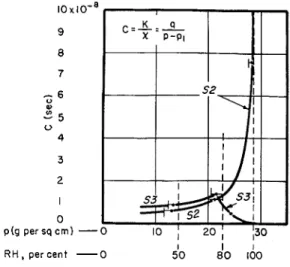
Fig. 6.-Vapor conductances of surface coatings S2 and S3.
RH, per cent - 0 $0 d0 Id0
Fig. 5.-Use of flow data for uncoated specimen in determining PI values for rating surface coatings S2.
mortar bars cured for 11 days a t 100 per cent relative humidity and 73.4 F, and then conditioned a t 50 per cent relative humidity and 73.4 up to 60 days. The slight but possible adverse influence of integral waterproofing ma- terials on drying shrinkage is illustrated by the following results: AOX (no ad- mixture)-0.071 per cent, A1X- 0.087 per cent, A2X-0.086 per cent, A3X- 0.077 per cent, and A4X-0.094 per cent.
The data in the preceding sections are for the rich mix only. Data for the mix B showed similar trends.
Specimens with Surface Waterproofing Materials
The Unsaturated Permeability Test.- The dry-cup test was carried out in the same manner as described previously. The rates of moisture flow were deter- mined for 50. 80, and 100 per cent rela- tive humidity conditions a t the painted side of the specimens. Test results ob- tained from the uncoated series SO were used to plot the qx curve of the uncoated concrete (Fig. 5). With the aid of this curve and with the experimental re- sults of the coated series, it was possible to obtain the moisture conductances of the surface waterproofing films, which will subsequently be referred to as paint films.
It
was considered that a partial pres- sure drop p -pl would be attained in the paint film, resulting in a smaller pres- sure drop pl-po in the concrete than it would have experienced in the uncoated state. Therefore the rate of flow q, ob- tained for the painted specimen would be smaller than the rate of q of the un- painted specimen. q1 was determinedexperimentally. To find pl, use was made of Fig. 5. A horizontal line was drawn from the point qlx to its inter- section of the qx curve. Then a vertical line was drawn leading down to the p, value. The pressure pl was deter- mined by this procedure for each of the cases and the moisture conductance of the paint film was calculated from the equation :
C = p l
P
-
PIand plotted against p, = (p
+
p1)/2, giving three points, one for each of the three tests a t 50, 80, and 100 per cent relative humidities. The three points were connected by a curve and the mois- ture conductance of the paint film was obtained for the whole range of vapor pressures. Only the results for points S2 and S3 are shown in Fig. 6 since S1 (cement paste) had no apparent effect in moisture flow. The curves show that:(a) paint S2 gave decreased flow rates; the curve of conductance had the same general shape as the curve of the unsaturated permeability coefficient of concrete; and
(b) paint S3 gave decreased flow rates, especially a t higher humidities; the curve of vapor conductance follows the curve of paint S2 up to 80 per cent relative humidity, but a t higher humidi- ties, instead of rising to higher values, it drops to a very low value a t 100 per cent relative humidity. This shows the re- markable effect of the silicone water- proofer a t higher humidities.
The special test of unsaturated per- meability with water and air on the two sides of the specimens was carried out by the inverted wet-cup metho d as de-
scribed previously. The paint film was applied (a) to the wet side, and (6) to the dry side. Results of tests (a)
again showed excellent agreement with the results of dry-cup tests; results of tests (6) showed no benefit except for the silicone waterproofer S3. This would indicate that the cement-base waterproofing materials were beneficial when they were painted on the upstream side but apparently not beneficial when they were painted on the evapora- tion side.
The Saturabd Permeability Test.- The test was carried out in the same manner as for the specimens containing integral waterproofing materials. The results showed that paints S1 and S2 did not affect the rates of permeability a t all. Paint S3, on the contrary, showed no leakage under the small head of wa- ter during the seven days of the test. As a matter of interest, a higher water pressure of 30 psi was applied resulting in definite leakage. After the specimens had leaked for one night and had become saturated, the pressure was decreased to its original small value. After that the leakage stopped again.
It
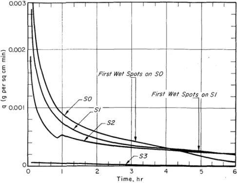
can be con- cluded that paint S3 was very effective against small water pressures.The Capillarg Absorption Test.-The capillary absorption a t 50 per cent relative humidity equilibriuni conditions was determined from the initial inflow measurements in the saturated permea- bility apparatus. The fact' that paint and concrete represented two different layers made it impossible t o establish a simple theory and to determine a coefficient of absorption a s described previously. Figure 7 shows the rates of absorption obtained for the series SO, S1, S2, and S3. As seen from this figure, S l and S2 decreased capillarity and increased the time of complete water penetration through the 1-in. specimens. For S3 water had not penetrated the sample to any extent even after 7 days.
Discussion and Conclusions
The test methods used in this inves- tigation, taken together, showed prom- ise as a means of evaluating integral and surface waterproofing materials. The results show clearly t h a t reliance o n one single test is not adequate. The ma- terials tested showed t o no advantage in the saturated permeability test. How- ever, this test may have some merit where filler-type or pozzolanic admix- tures are used. The unsaturated per- meability test appeared t o make clear distinction between certain types of waterproofings and could be related to certain field situations. I n practical testing it may not be necessary to apply both the clry-cup and the wet-cup meth- ods unless field conditions warrant it. The capillary absorption test gave a good indication of the over-all effective- ness of ~vaterproofings in cases where concrete is subjected t o short periods of contact with moisture, with interme- diate drying intervals.
The water repellent and bituminous admixtures showed up favorably in all the tests except t h e saturated permea- bility test. The calcium chloride ad- mixture showed no beneficial effects in this study, apparently because the ce- ment used did not respond t o the usual accelerating action of calcium-chloride o n hydration.
The cement-base paints provided varying degrees of benefit when painted on the side of the specimen subjected t o wetting. The silicone application had
a very significant influence on moisture flow.
The differences obtained with water- proofing agents used in these studies in- dicate t h a t the combination of tests de- scribed provides a simple and useful means of evaluating such materials on the basis of the different field problems which may be anticipated.
The tests, however, were limited t o isothermal conditions and t o relatively early ages of concrete. T h e influence of age and temperature gradient, a s well a s durability and corrosion resistance prop- erties, require additional investigation before final conclusions can be drawn.
Acknowledgmenl:
T h e authors acknowledge the con- structive criticism afforded during the course of this study by
N.
B. Hutcheon,P.
J.
Sereda, andJ.
M. Icuzmak, all of the Division of Building Research, National Research Council, Ottawa, Canada.72
(TP
90)
0003 I I I I I I I I I I I I - - I-
-
- - Flrsf Wet Spots on S l - - - 0 I 2 3 4 5 6 Time. h rFig. 7.-Capillary flow with surface coatings S1, S2, and S3; compared with uncoated
specimen S O
(1) C. H. Jumper, "Tests of Integral and Surface Waterproofings for Con- crete," Proceedings, Am. Concrete Inst., Vol. 28, NO. 13, p. 209 (1931). (2) G. W. Washa, "Efficiency of Surface Treatments on the Permeability of Concrete," Proceedings, Am. Con- crete Inst., Vol. 30, No. 1, pp. 1-8 (1933).
(3) C. G. Walker;!'Tests of Integral and Surface Waterproofings," Discussion of report of Committee 704, Pro-
ceedings, Am. Concrete Inst., Vol. 38,
p. 316 (1942):
(4) F. 0. Anderegg, "Results on Testing Surface Waterproofers," ASTM BUL
LETIN, NO. 171, p. 48 (1951) (TP10).
(5) F. 0. Anderegg, "Research Report: Surface Waterproofing with Silicone Resins," Progressive Architecture,
May, 1951, pp. 94-96.
(6) ACI Committee 212, "Admixtures for Concrete; Damp-proofing and Permeability Reducing Agents,"
Proceedings, Am. Concrete Inst.,
Vol. 51, No. 5, p. 129 (1954). (7) E. G. Swenson, "The Durability of
Concrete Under Frost Action," N R C 3677, National Research Council, Div. of Building Research (1955). (8) T. C. Powers, "The Physical Struc-
ture of Cement and Concrete," Ce-
ment and Lime Manufacturer (Lon-
don), Vol. 29, No. 2, p. 13 (1956).
(9) L. A. Richards, "Capillary Conduc-
_
tion of Liquids Through Porous Me- diums," P+ysics, Vol. 1, p. 318 (1931).A S T M B " . U L L E T I N
(10) A. Iilute, "Some Theoretical Aspects of the Flow of Water in Unsaturated Soils," Proceedings, Soil Science Soc., Vol. 16, No. 2, p. 144 (1952). (11) W. L. Hutcheon, "Characteristics of
Moisture Movement in Unsaturated Soils," Proceedings, N R C 5568, Con- ference on Building Research, Ottawa (Canada), National Research Coun- cil, p. 74 (1955).
(12) J. D. Babbitt, "The Diffusion of Water Vapour Through Various Building Materials," Canadian Jour-
nal of Research, Vol. 17, Sect. A, p.
15 (1939).
(13) J. S. Cammerer and P. Gorling, "The Water Vapor Permeability of Building and Insulating Materials and the Possibility of Condensation in Walls," Fortschritte und Porschun-
gen i m Bauwesen, Reihe D, Heft 3, p.
57 (1952).
(14) T . C. Powers, "Hydraulic Pressure in Concrete," Proceedings, Am. Soc. Civil Engrs., Vol. 81, p. 742 (1955). (15) F. M. Lea and C. H. Desh, "The
Chemistry of Cement and Concrete. Integral Waterproofers," Edward Arnold and Co., London, p. 354 (1935).
(16) E. Madgwick, "Water Movements in Porous Building Materials," Int. Assn. for Testing Mats., London Conference, April 19-24, 1937, Pro-
ceedings and Papers, Group (B-48)