Publisher’s version / Version de l'éditeur:
Forest Products Journal, 14, 3, pp. 129-136, 1964-04-01
READ THESE TERMS AND CONDITIONS CAREFULLY BEFORE USING THIS WEBSITE. https://nrc-publications.canada.ca/eng/copyright
Vous avez des questions? Nous pouvons vous aider. Pour communiquer directement avec un auteur, consultez la première page de la revue dans laquelle son article a été publié afin de trouver ses coordonnées. Si vous n’arrivez pas à les repérer, communiquez avec nous à [email protected].
Questions? Contact the NRC Publications Archive team at
[email protected]. If you wish to email the authors directly, please see the first page of the publication for their contact information.
NRC Publications Archive
Archives des publications du CNRC
This publication could be one of several versions: author’s original, accepted manuscript or the publisher’s version. / La version de cette publication peut être l’une des suivantes : la version prépublication de l’auteur, la version acceptée du manuscrit ou la version de l’éditeur.
Access and use of this website and the material on it are subject to the Terms and Conditions set forth at
Snow loads and strength of small roofs in Canada
Schriever, W. R.; Hansen, A. T.
https://publications-cnrc.canada.ca/fra/droits
L’accès à ce site Web et l’utilisation de son contenu sont assujettis aux conditions présentées dans le site LISEZ CES CONDITIONS ATTENTIVEMENT AVANT D’UTILISER CE SITE WEB.
NRC Publications Record / Notice d'Archives des publications de CNRC:
https://nrc-publications.canada.ca/eng/view/object/?id=3a66cf85-6c53-4f8f-9e11-d0b7ed82b444 https://publications-cnrc.canada.ca/fra/voir/objet/?id=3a66cf85-6c53-4f8f-9e11-d0b7ed82b444s e r
TH1
N21r
2
no.
216
I c.2
BLDG National Research Council
C a n a d a
Division of Building Research
Snow Loads and Strength
of Small Roofs in Canada
BY
W.
R.
Schriever andA.
T. HansenREPRINTED FROM
FOREST PRODUCTS JOURNAL
Vol. XIV,
No.
3
March
1964,
p.129-
136RESEARCH PAPER N O , 216
OF THE
DIVISION OF BUILDING RESEARCH
BUILDING R E S E A R C H
-
I-IBRARY
-
SEP 17
1964
NATIONAL RESEAHEH COUNCIL
PRICE
25
CENTS
OTTAWA
APRIL
1964
T h i s publication i s b e i n g d i s t r i b u t e d b y t h e Division
of B u i l d i n g - R e s e a r c h of t h e N a t i o n a l R e s e a r c h C o u n c i l ,
I t
s h o u l d not b e r e p r o d u c e d i n whole o r i n p a r t , w i t h o u t p e r m i s
-
s i o n of t h e o r i g i n a l p u b l i s h e r .
The D i v i s i o n would b e glad to
be of a s s i s t a n c e in o b t a i n i n g s u c h p e r m i s s i o n .
P u b l i c a t i o n s of t h e Division of B u i l d i n g R e s e a r c h m a y
b e o b t a i n e d b y m a i l i n g t h e a p p r o p r i a t e ~ e m i t t a n c e , (a B a n k ,
E x p r e s s , o r P o s t Office Money O r d e r o r
acheque m a d e p a y -
a b l e a t - p a r i n O t t a w a , t o t h e R e c e i v e r G e n e r a l of C a n a d a ,
c r e d i t N a t i o n a l R e s e a r c h C o u n c i l ) t o t h e N a t i o n a l
R e s e a r c h
Snow Loads and
Strength
of
Smal Roofs
in
Canada
A # 2 a e-%" .y
L
y"
BY L -1
W. R.
Schrieverand A. T.
HansenNational Research Council of Canada Division of Building Research
Ottawa, Ontario
T
H E lrios~ IMPORTAN?. I ~ E Q u I R E - 1'0restry in Ottawa, undertook a study Both factors are of equal importance lnent for a r.oof is that it should of the load-carrying and deflection since failure of either the rafters or be able to support, without collapse characteristics of conventional and the tie will cause c,ollapse of the roof. or excessive deflection, any imposed trussed roofs. T h e immediate objec- ~ 1thrust exerted by the , ~ rafters on loads to be expected during its life. ,, tive was to develop performance cri- the tie depends on the applied livem
most areas of Canada, and some teria for the acceptance of trusses f o r laid and the m d the slolr of the parts of the northern United States. hollses built under the National Hour- iranle, ~ 1 thmst , ~the greatest, and therefore most im- ing Act administered by the Central be seen from ~i~~~~ I , The i'ortmt, load f o r which n roof must , Mortgage and Housing Corporation.
most importmt variable i s the slope; be designed is the snow load. This pk'er summarizes the of the thrllst increases progressi\reJy as Many people instinctively appreci- the work done by the Divisi,on o f the ,lope is decreased, A 3 / 1 2 roof ~ t e the importance, and the dangers, of Building Research a n d tile conclusions ,ith a span of 28 feet, for erunple, snow loads o n roofs. O n e would ex- reached. will have a thrust of 1400 pounds per pect to see this reflected in the gen-
eral standard of roof construction, but Structural Action o f Conventional of roof length under a 50 p.s.f. Roof Frames roof load. This is a large force, and it is surprising h.ow inconsistent the Conventional w o o d roof frames the most important nailed connections handling of snow loads and the
consisting of sloping rafters and hori- are the heel joint between rafters and strength of small roofs has been in joists and any splice of the ceiling rhe past. Although most roofs on zontal ceiling joists ( p l u s c o l l a r
large commercial buildings are de- beams) rely on tw.0 things t o carry joists,
signed by professionals in accordance loads: the bending stren@h Before discussing the strength of with standard engineering methods, of the rafters and 2 ) the tying action existing roofs, which in many cases is the majority of conventional house of the joints which, if properly nailed low, a brief summary will be given of roofs in c a n a d a have been built to the rafters, keep the rafters from the sn.ow loads to be resisted by small largely on the basis of tradition and spreading under t h e applied load. roofs.
experience. T h e size of the members
(rafters and joists) has been speci- 1800 tied for some time in "span tables,"
but the nailing used for the connec-
tions between the members have, until 1600 recently, been usually left to the
know-how of the carpenter. This has
resulted in a variety .of constructions I4O0 that have far too wide a range of load- S
c ~ r r y i n g capacities f o r roofs that are ? intended to carry the same amount of I2O0
load. o LT
A considerable amount of research
and development work in this field Ioo0 has been done in recent years, particu-
g
larly in the United States, which has L-resulted in many publications. A few
E
8 0 0 of these are listed in the Bibliographya
mainly t o indicate some of the organi-zations that have been active in these
';
6 0 0 studies. In all this work, however, not2
\.cry much attention has been given to
Z
the loads that act on small roofs and 4 0 0 minimum perfor~nance requirements.
T h e Division of Building Research
of the National Research Council, in 200 cooperation with the Forest Prodilcts
Research Branch of the Department of
0 I I \ I I I I I 1
-
50 PSF - - - ~ - - - - - - -\.----
- - I I I I I I 1 I I T h i s p a p e r w a s presented a t the 17thx2
2/;2 3/(2'X2
5/;26/;~ 7/;~
%
%2Annual Meeting of the Forest Products Re- SLOPE OF ROOF search Sociely, Session 1 1 , Wood Engineer-
ing, June 1 9 , 1 9 6 3 , in N e w Orleans, La. Figure 1 .-Variation of horizontal thrust for a simple frame of various spans under a l o a d of 5 0 p.s.f.
Design Snow Loads and Survey o f Actual Snow Loads o n Roofs Snow loads o n roofs vary widely ac- cording t o geographical location (cli- m a t e ) , site exposure, and shape of the roof. In perfectly calm weather snow would cover the roof and the ground with a uniform blanket of snow and if this calm continued, the snow cover would remain undisturbed. T h e pre- diction of roof loads would then be a selatively simple matter since the de- sign roof load could be specified equal to a suitable statistical maximum of the ground snow load for which rec- ords covering many years are avail- nble. Truly uniform loading condi- tions are rare, however, since in most regions snowfall is accompanied or followed by winds. Since many roofs are well exposed to the wind much of the snow will be blown off. T h e shapes and exposures of some roofs, however, are such that due to turbu- lence the air speed is reduced suffi- ciently over certain areas to cause the snow to settle in drifts. Drifts occur particularly o n roofs situated below adjacent higher roofs, behind chim- neys and other projections and o n the leeward side of peaked and curved roofs.
Although information o n ground snow depth is readily available fro111 meteorological sources, additional in- formation is required on actual snow loads on roofs. This is being collected in Canada by the Division of Building &search in a country-wide survey of snow loads on roofs ( 1 ) . At numer- ous stations over the last 7 years ob- servers have made depth and density measurements on v a r i o ~ ~ s roofs to pro- vide infornlation regarding the rela- tionship between ground and roof loads for various types of roofs.
Early results of the survey enabled the conlmittee responsible for the 1960 revision of the National Build- ing Code of Canada ( 2 ) to reduce the basic roof load t o 8 0 percent of the
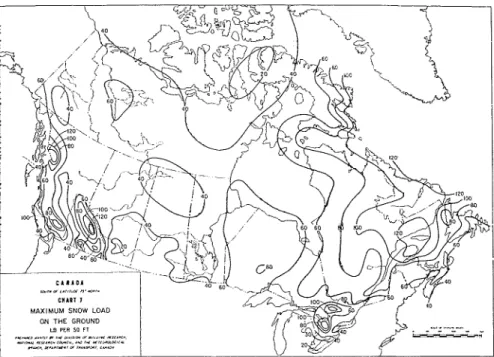
Figure 2.-Chart showing maximum snow l o a d on ground in Canada. Figures, based on d a t a for 1 9 6 0 , show maximum l o a d in pounds per square feet.
ground load, the ground load being calculated o n t h e basis of the maxi- mum load that would occur once in 30 years with an allowance for the in- crease in the load caused by rain wa- ter absorbed by t h e snow (Figure 2 ) .
Factors are also provided to increase these basic loads where drifts are anticipated.
T h e survey has shown that the ma- jority of roofs are quite exposed to winds, and therefore usually collect much less snow than one would expect from the snow observations on the ground. These exposed roofs, particu- larly older and steeper ones, seldom experience more than about 30 to 50 percent of the ground load. T h e few roofs that .are well sheltered by trees, however, collect a high percentage ( u p to 8 0 or 9 0 percent) of the ground load. Even higher loads, solnetimes considerably exceeding the g r o u n d load, w~ere found to occur due to drifting o n certain shapes of roofs,
such as the lower level of split-level roofs (Figure 3 ) . T h e study has also indicated that, although several factors besides wind affect snow loads, sornc- factors, such as heat loss through t h e roof a n d solar radiation, are only effec- tive in relatively mild weather and can- not be relied upon to reduce the loads. Should these infrequent conditions govern the snow loads f o r all roofs? T h e answer is no, if these conditions can be predicted. Sheltered roofs, f o r example, should be designed for higher loads than the average exposed roofs. Obviously, the more accurate thc de- sign loads, the more accurate ( a n d therefore the more econornic'11) will bc- the construction.
In summary, i L can be said that knowledge of snow loads on roofs. while increasing. is still incomplete. As an expedient t o the evaluation of roof trusses for houses, therefore, it was considered desirable, in deciding o n the required nlinilnunl performance,
Figure 3.-Example of a drift load on portion of roof adjacent to and west of higher roof. The maximum snow depth is 3 % feet, or approximately 6 0 pounds per square foot. Note 3-foot gauges i n
snow. Figure 4.-Test setup for short-term tests.
Deflections
Deflections were incnsured at e;tcll panel point and midway between each panel point for both the upper ancl lower chords. The measurements were made by ~ n e a n s of p i a n o w i r e s , weighted at onc end and stretcheti along the chord menibcrs.
Supports
T h e con1,entional roof frames wcrc- tested both o n fixed-end supports bolted rigidly on to the floor to rc- sist outward thrust, and on roller sup- ports. T h e former represents a lateralll- stabilized exterior wall as a support. the latter a laterally unstabilized exte- rior wall. T h e joists in con~~cntional roof frame tests were supported at the center of the span near the splice, rep- resenting a typical load-bearing ~vall. Exploratory tests on trusses had indi-
Figure 5.-Test setup for long-term tests with concrete blocks stacked on roof structure. cated that 'the type of end support did
not have a n important effect on truss to consider past experience with con- Testing Equipment and Loading performance. Most of the trusses were,
ventional roofs. Procedure therefore, simply supported on 2 x 4
Objective a n d Scope of Experimental W o r k It was recognized early that trusses designed according to standard engi- neering procedures would be much stronger and more expensive to build than conventional roof frames. Since there appeared to be no need for trusses to be essentially stronger than well-built conventional roof frames, which had a history of generally satis- factory performance, it was decided to investigate the strength of various types of conventional frames first and only then proceed with the develop- ment of trusses.
Most of the work carried out con- cerned W-trusses with nailed plywood &usset plates. T h e test program orig- lnally envisaged only short-term load- ing tests. Later it was decided to add some long-term loading tests to study the effects of such loading on deflec- tion.
T h e program also included other aspects such as the effect of locating pnrtitions under trusses and the effect of cantilevering trusses beyond the ex- terior wall.
All structures were tested in pairs, and the majority were sheathed with plywood to provide lateral stability. This sheathing provided sufficient re- sistance to prevent lateral buckling ex- cept in the few cases where lumber sheathing was used.
Loading Means
Short-term loads were applied by means of eight equally spaced hy- draulic tension jacks, anchored to the floor and located at t h e an el ouarter- 1
points midway between the pairs of trusses or rafters (Figure 4 ) . T h e weight of the test assembly was ap- proximately equal to the dead weight of the roof cover so that the reported loads are in addition to theA dead weight of the roofing and sheathing. For the long-term loading tests, roof loads were applied with concrete blocks, stacked to prevent arching action be- tween units (Figure 5 ) . In all cases a ceiling load equivalent to 10 p.s.f. was applied to the lower chords with weights located at the quarter-points of each panel.
Figure 6.-Sketch of conventional roof frame. Lumber used was NO.
1 construction grade Eastern or White spruce (Canadian Lumbermen's Association grade rules) ; nails used were 3 %-inch common applied as follows: 3 to join joist to rafter, 3 joist to joist a t center, 2 toenails a t each end of each joist to plate. 3 toenails each end rafter to plate, 3 nails each end of collar tie to rafter.
F O R E S T P R O D U C T S J O U R N A L
.
, A.plates resting directly o n concrete blocks.
Loading Procedure
T h e loading procedure f o r short- term tests varied during the testing pro- gram. In the first series of tests, trusses and conventional frames were loaded in increments to a 40 p.s.f. simulated snow load and a 10 p.s.f. ceiling load, after which the roof load was removed to record the recovery. Loads were then re-applied in increments until failure occurred. The load increments were applied for 5 minutes before de- flections were recorded.
During the latter part of the pro- gram, this procedure was modified and trusses were loaded in increments up to the design snow load. T h i s load was maintained for 1 hour, and deflections were recorded after 5 minutes and after 1 hour. The roof load was then increased in increments to twice the design snow load and maintained for
24 hours after which t h e load was in-
creased in increments until fdilure oc- curred.
For the long-term tests, the struc- tures were loaded for 1 month and
Figure 7.-Conventional roof frame w i t h weakest type o f heel joint. Three 37/2-inch nails were used to join joist to joist a t center, three 3 '/~-inch nails were used to join collar tie to rafter, two &inch nails a t header a n d joist, one 4-inch nail a t rafter p l a t e to joist, one 4-inch n a i l rafter plate to header, three 3 '/2-inch toe nails rafter to rafter plate, and two 3 %-inch toenails joist to joist plate.
then unloaded to permit observation of recovery for 1 month. In all cases the deflections were recorded 5 min- utes after load application or removal .und ; ~ t increasing time intervals from then on.
Structures Tested Conventional Frames
The conventional roof fra~nes tested .Ire shown in Figures 6 and 7. The lum- ber used was N o . 1 Construct~on grade (Canadian Lumbermen's Assoc.) Eastern or White Spruce ( 3 ) . T h e nailing at the joints confornled to the r e q ~ ~ i r e m e n t s of the 1953 National Building Code of Candda ( 4 ) and the l g j S Housing Standards ( 5 ) . For those nailed connections for which there were n o specified requirements in these documents, nailing considered to repre- sent good building practice was used. It should be noted that the nailing specified in the 1953 National Build- ing Code ( 4 ) and the 1 7 5 s Housing Standards ( 5 ) was generally superior to the nailing observed in many actual house roofs b~lilt in Canada accord- ing to the brief survey made prior to the test program.
Since this series of tests on conven- tional roof frames was carried out, further investigations on conventional roof frames have been undertaken as a separate program to determine the effect of nailing, roof slope and span length on the performance of such fr'unes.
Trusses
T h e lumber used in the tests was No. 1 Construction grade Eastern or White Spruce ( 3 ) . T h e member size for the top and bottom chords was generally 2 by 4 inches but this was increased in a number of cases to 2 by 5 or 2 by 6 inches, as shown in the tables and figures, for additional strength or to obtain comparative test results.
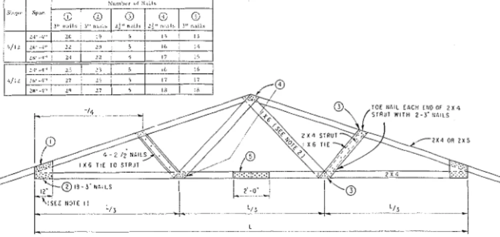
Figure 8.-Sketches of nailed W trusses with 4 / 1 2 or 5 / 1 2 slopes. Lumber used was CLA No. 1 construction grade Eastern or White Spruce, plywood was l/2-inch sheathing grade Douglas-fir, and nails were 21/2-inch and 3-inch common. Note 1: a 16-inch plate was used when the number of nails required i n columns 1 and 2 exceeded 20; Note 2: 1 b y 8 diagonals were used when number of nails required in column 4 exceeded 12.
Figure 9.-Sketches of nailed W truss with a 4 / 1 2 slope. Lumber was CLA No. 1 spruce, plywood was 1/2-inch sheathing grade Douglas-fir, and nails were 3-inch common. unclinched.
T h e number of nails used in the earlier part of the truss study was based on a design roof load of 35 p.s.f. and a ceiling load of 10 p.s.f. T h e al- lowable lateral load for a 3-inch nail was taken to be 102 pounds in double shear and 4 3 pounds for a 2%-inch nail in single shear (Table 4.3.12(a) of the National Building Code, 1760) ( 2 ) . T h e designs determined on this basis are shown in Figures 8, 9 and Table 1 .
-
RESULTS OF S H O R T - T E R M TESTS ON C O N V E N T I O N A LJOIST-RAFTER F R A M E S
T y p e o f Construction
T y p e o f End Ultimate* Rafter Collar Tie Supports Roof L o a d
Figure 6 Figure 7 Inches Inches Rollers Fixed Rollers Fixed Rollers F i x e d Rollers Fixed P.S.F. 2 x 4 2 x 4 Rollers 1 8 2 x 4 2 x 4 Fixed 1 8 2 x 8 2 x 4 Rollers 4 6 2 x 8 2 x 4 Fixed 46
*In addition to 10 psf ceiling load. Average of three tests. Lumber: N o . 1 (Construction) grade Eastern or W h i t e Spruce; Joist Size: 2 x 6 inches, spaced 16 inches.
10. In some of the later tests, the nurn- ber of nails was reduced t o 2/3 a n d
1/2
of the original nailing t o determine the effect of nailing reduction on over- all strength and stiffness of the assem- bly.Results o f T e s t s Conventional Roof F r a m e s
As shown in Table 1 , the conven- tional roof frames showed an ex- tremely wide range of failure loads from 18 to 125 p.s.f. depending on heel joint details, size of rafters a n d type of end support. T h i s range of failure loads is quite surprising when one considers that all the types of roof frames tested have been built in the same area, for the same load, 2nd t o satisfy t h e same code.
As o n e xvould espect, the type of conventional frame shown in Figure 7 showed particularly low strength ( 1 8 to 4 6 1.1.s.f.) hecause of the weal<ness of the heel joint in transferring thrust from the rafters to the joists, hereas as frames of the type shown in Figure 6 had failure loads from 56 to 125 p.s.f. In both types of constructions, the f r a 111 e s were considerably stronger
\ v l ~ ' ~ n 2 by 6 or 2 by 8 rafters were used instead of 2 by 4 rafters, even M A R C H 1 9 6 4
Table 2.
-
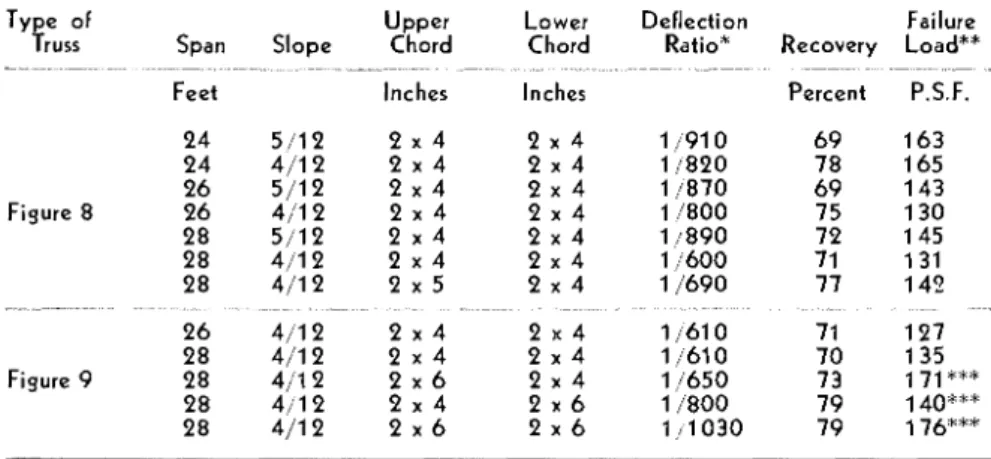
RESULTS OF S H O R T - T E R M TESTS ON W TRUSSES Type of Upper Lower Deflection FailureTruss Span Slope Chord Chord Ratio* Recovery Load**
.. ~ -~~~ ~-~ -F 24 5 / 1 2 2 x 4 2 x 4 1/91 0 6 9 1 6 3 2 4 4 / 1 2 2 x 4 2 x 4 11820 7 8 165 2 6 5/12 2 x 4 2 x 4 11870 6 9 143 Figure 8 2 6 4 / 1 2 2 x 4 2 x 4 1 /800 75 1 3 0 28 5 / 1 2 2 x 4 2 x 4 1 1890 72 145 28 4 / 1 2 2 x 4 2 x 4 1 i 6 0 0 71 131 77 1 4 2 ~. -~-. 71 1 2 7 7 0 135 Figure 9 28 4 / 1 1 2 x 6 2 x 4 1 /650 73 1 28 4 j l 2 2 x 4 2 x 6 1 /800 7 9 140:":" 28 4/12 2 x 6 2 x 6 1 / . I 0 3 0 7 9 176%""
written into the I963 Housing Stand- ; i d s ensure that trusses will actually be solnewhat stronger than good conven- tional rtmf Irames which on the aver- age \vould probably only c;irry 1.4 times the desigil sno\v load \vherl n;iilcd ;iccordin~ to the 1963 Housing St;inclxrds.
Trusses
T h e results o i the tests on tri~sscs shown in Tahle 3 arc based on tests conrlucted to satisfy these new per- formance critcrix; whereas, the results oC tests reported in Table 2 were con- ~luctctl hefore the crilcria were clcvel- ol>ed. From the m.my tcsts cxrried out thcrc were sufiicicnt cl;~ta ;~v;~ilahle on the factors :iffecting the strength and deflection of lrusscs to permit the ev:iluation of the results given in Table 2 in the light of these performance criteria.
*Deflection ratio of lower cord based on a roof load of 4 0 p.s.f. plus a ceiling load of 110
p.s.f. * * A d d ceiling load of 1 0 p.s.f. **"Based on one test each, all other values based:on average of three tests. Lumber was N o . 1 Construction grade Eastern or White Spruce.
though the same number of nails was mLum failure load of about 70 p.s.f. used' and the failures occurred at
the nailed connections (heel join1 or center joint splice). This increase in strength with rafter size can be at- tributed ~nainly to the fact that the stiffer the rafter the less influence the collar tie (or "collar strut" since it is in compression) has in contributing to the outward thrust of the rafter.
for conventional frames built in snow load areas of 50 p.s.f. These failure loads refer, of course, to short-term loading tests; for longer duration loadin6 the failure load might be be- low tlus value.
I ~ ~ ~ L ' c I
01
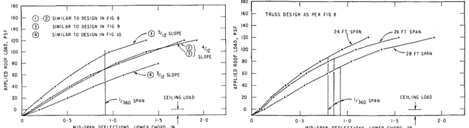
r o o / .r/rn/)e.--The e f - fect of roof slope on truss deflection is s l ~ o w n in Fig11re 1 1 for trusses with 2 by 4 members with nailing calcu- lated for the same roof load. It will be seen that- the truss with the 3/12 slope deflected Inore than twice as much as the trusses with 5/12 slope even though the nailing was calcnlated for the sume loading in all cases. This is explained by the fact that the de- formation of the truss caused by agiven amount of nail slip at t h e joints and deflection caused by axial strains in the members is increased as the slope is decreased.
The average failure load f o r these trusses was 107 p.s.f. for t h e 3/12 slope, 1 3 1 p.s.f. for the 4/12 slope ;unrl 145 p.s.f. f o r the 5/12 slope.
N e w Performance Criteria f o r Trusses
C o n v e n t i o n a l frame construction built in accordance with the require- ments of the 1953 National Building Code ( 4 ) (i.e. before the improve- ments of the 1963 Housing Standards ( 6 ) ) has now been used for a n u n - bcr of years and has, 011 the whole,
zpparently given a satisfactory per- formance since no failures have conle to the attention .of t h e Division of Building Research. It seemed justified therefore to use this experience with In practice, the n ~ o s t colnmon type
of construction being built is the type shown in Figure 6 with 2 by 6 rafters. This type of roof frame had a failure load between 62 and 113 p.s.f. de- pending on whether the supports were on rollers or were fised. Since nor- mally the exterior walls of a house would provide l ~ t t l e resistance to rafter spread, the failure load in prac- tice would probably be closer to the 62 p.s.f. value.
The results of some long-term tests on conventional c o n s t r u c t i o n a r e shown in Table 4.
Nailing requirements for conven- tional roof frames in Canada have been increased since these tests were carried out, so that present require- ments as given in the 1963 Housing Standards ( 6 ) , will ensure a mini-
conventional roof frames for the es- tablishment of minimum performance criteria for trusses. T h e criteria re- quire that a truss be able to withstand at least twice the design snow load, plus the ceiling load, f o r 24 hours and that it deflect n o more than 1/360th of the span under the full design load after 1 hour of loading. These criteria
E f f e c t of l~.r/.rs .r/~d~l.-As Figure 12 shows, trusses with [he same slope with the nailing designed for the same load, are stiffer the shorter the span. T o produce a deflection of 1/360th of the span, for example, 7 1 p.s.f. was re- quired for the 28-foot truss, 84 l~.s.f. for the 26-foot truss, and 87 p.s.f. for the 24-foot truss.
Table 3.
-
S H O R T - T E R M TESTS ON TRUSSES TO D E T E R M I N E A C C E P T A B I L I T Y FOR V A R I O U S S N O W LOAD A R E A S- --
Lower Chord Deflection Ratios Maximum After 1 H o u r Loading Roof Load
- - - - . - - -- -- - -
Sustained
30 psf 4 0 psf 6 0 sf for Roof Load* Roof Load* Roof L o a d * 44 Hours *
- -- - - - - - - - - - --
P.S.F. Upper
Chord Span Slope Size
Lower Chord Size Average Failure Load* Type of Truss -- - . - - - .
Feet Inches Inches P.S.F.
Figure 1 0
N o t e 1 Below N o t e 2 Below
N o t e 1 Trusses shown in Figure 8 except that the number of nails was reduced to 5 0 % of the number shown in Figure 8. N o t e 2 Trusses shown in Figure 8 except that the number of nails was reduced to 2/3 of the number shown in Figure 8. *In addition to 1 0 psf ceiling load. Average of three tests. Lumber: N o . 1 (Construction) grade Eastern or W h i t e Spruce.
Eiect of /r.//ss nzenzbei. sizes.-Fig- ure 1 3 indicates the effect of member size on the deflection when other fac- tors are kept constant. The curves show the changes resulting from sub- stituting 2 by 6 for 2 by 4 members. When 2 by 4 members were used throughout, the roof load required to cause a deflection of 1/360th of the span was 68 p.s.f. When 2 by 6 top chords were used the load was 79 p.s.f., when 2 by 6 bottom chords were used the load was 81 p.s.f., and when
2 by 6 top and bottom chords were used it was 102 p.s.f.
The failure load obtained in these tests was 135 p.s.f. for 2 by 4 mem- bers only, 140 p.s.f. with 2 by 6 bot- to111 chords, 171 p.s.f. with 2 by 6 top chords and, finally, 176 p.s.f. with 2
by 6 top and bottom chords.
Efict of ?znili~zg.-Failure load and deflection are considerably (but not proportionately) influenced by t h e number of nails as indicated by Fig- ure 14. When the nailing was reduced by 33 and 50 percent of the nailing, as shown in Figure 8, the load produc- ing a deflection of 1/360th of the span was reduced by only 23 and 38 per- cent, respectively. The failure load was reduced by 20 and 40 percent, respec- tively. The trusses did not fail at the joints, even when the nailing was re- duced by 50 percent. Failure was in- variably due to the bending failure of the chord members. It must be as- sumed, therefore, that the reduction in load-carrying capacity must have been caused by a net increase in total stresses due to the greater distortion of the trusses with the reduced nailing.
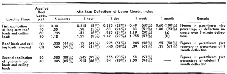
Efect of dnrdtioJ2 of loddiizg of tt~zcsses.-The deflection of trusses un- der longer term loading may be seen from Table 5 for various roof loads. The average percentage increase in de- flection of these trusses after a given time interval was nearly constant and relatively independent of the applied load. The average increase in deflec- tion after 1 hour was 6 percent, after
Figure 10.-Sketches of nailed W truss with 3 / 1 2 slope. Lumber was CLA No. 1 spruce, plywood was %-inch sheathing grade Douglas-tir, and nails were 3-inch common, unclinched.
one day 26 percent, after 1 week 55 percent, and after 1 month 97 percent. During this series of tests, the pair of trusses loaded to 80 p.s.f. roof load collapsed after 1 2 days due to lateral instability; the trusses loaded to 60 p.s.f. coilapsed after 2 2 days. These failures cannot be considered signifi- cant failures since the same trusses in- stalled in a house roof would receive considerably more lateral restraint than was provided in this test on only a pair of trusses sheathed with 6-inch boards. The remaining trusses contin- ued to show deflection recovery even 1
month after the loads were removed. Application of Results One o f the purposes of the test pro- gram was to show if it is possible in developing new designs to extrapolate safely from known test results to cer- tain variations in spans, slopes and nailing. T h e tests indicated that if the design load per nail and the member size are kept constant the performance of shorter spans and steeper slopes can be conservatively predicted from tests on trusses with longer spans and flatter slopes. T h e tests also showed that the number of nails can be safely reduced in proportion to the design roof load for trusses intended for a lower snow load.
The results were also used to pre- dict the 24-hour performance from short-term tests. As already mentioned, the results shown in Table 2 were de-
-
0-0
S I M I L A R TO D E S I G N I N F I G 8 - @ S I M I L A R TO D E S I G N I N F I G 9 @) S I M I L A R TO D E S I G N I N F I G 10 - - SLOPE / S P A N C E I L I N G LOAD1
I I 0 0 . 5 1.0 1.5 2 . 0 M I D - S P A N D E F L E C T I O N S , LOWER CHORD. I N .Figure 11.-Deflection curves for various designs of 28-foot span trusses with 2 by 4 u.pper and lower chords and nailing schedules cal- culated for similar loadings.
rived from short term tests before the performance criteria discussed pre1.i- ously were developed. O n the basis of the results shown in Tables 3 and 5, the perfornlance of the trusses in Table
2 were assessed with regard to these
-
performance criteria.T h e precise relationship between the maximum load that can be carried by a truss over a 24-hour period as com- pared to the short-term failure load is difficult to establish without extensive testing. Some use can be made however of the information in Table 3, showing the 24-hour load carried by the trusses, and the corresponding failure loads when the trusses were tested to destruc- tion. T h e 24-hour proof loads shown in Table 3 are not necessarily the larg- est 24-hour load that could have been carried, however, since the 24-hour proof loads were applied only in 20 p.s.f. increments.
In examining the results of Table 3, it can be seen that t h e ratio of the 24-hour proof load to the short-term failure load was 0.76 for a 28-foot span with a 4/12 slope with the nail- ing reduced by 33 percent of that shown in Figure 8. I n applying this ratio to the measured failure loads shown in Table 2 to predict the maxi- mum 24-hour proof loading that could be carried, the results should be on the conservative side. By applying this ratio to the failure loads in Table 2, it will be seen that all but two trusses would support a 24-hour proof loading
T R U S S D E S I G N A S P E R F I G 8 , - 1 4 0 Y1 n
-
120 CI 4 S loo , 8 0 h o 2 n 2 4 0 2 0 0 - - - - - - C E I L I N G LOAD - - I 0 0 . 5 1 . 0 I1
2 - 0 M I D - S P A N D E F L E C T I O N S . LOWER CHORO. I N .Figure 12.-Deflection curves for 4/12 slope trusses of various spans with 2 by 4 upper and lower chords and nailing schedules calculated for similar loadings.
2 0 0
I
II
I
I II
hours and must not deflect more than 1/360th of the span under the design load after 1 hour. These criteria will-
provide trusses which are even a little
%
I 6 0 - stronger and stiffer than most conven-LL tional roof frames.
A number of standard designs were developed f o r trusses with spans vary- ing from 24 to 32 feet and slopes varying from 3/12 to 5/12 that would
-
3 - meet the performance criteria described
0
above for snow loads varying from 30
- to 50 11.s.f. The designs were devel-
C3
w - oped jointly with the Forest Products
Research Branch of the Department of Forestry of Canada for use by the Cen-
-
tral Mortgage and Housing Corpora- tion ( 7 ) .
-
Factors Affecting T r u s s Performance During the test program a number of factors affecting the strength, stiff- - 0 0 ~ 4 0 sf30 1 - 2 0 1 - 6 0 2 - 0 0 z e 4 0 2 ' a 0 ness and long-term performance of
M I D - S P A N D E F L E C T I O N S , LOWER CHORD, IN. trusses were investigated which may be su~nmarized as follows.
Figure 13.-Relationship between load and mid-span deflection for trusses similar in design Truss strength depends to some ex- to that shown in Figure 9, with a 28-foot span, 4 / 1 2 slope, and similar nailing but different
member sizes as follows: 11 2 by 6 top and 2 by 4 bottom chords (one test only); 2 ) 2 by 4 tent upon truss stiffness. ~n trusses
top and 2 by 6 bottom chords (one test o n l y ) ; 31 2 by 6 for both top and bottom chords with the same member size a n d geome- (one test only); and 4 ) 2 by 4's for both top and bottom chords (overage of three tests). try but with joints designed f o r differ-
ent loadings, stiffer trusses will have
of 100 p.s.f., 2nd of these two, the Housing Standards which take into ac- higher failure loads provided failure weakest truss should be able to with- count variations in span, slope, and occurs in the members and not the stand a 24-hour proof loading of 97 snow load. I n addition, improxTements joints.
p.s.f. Considering that the 0.76 factor in t h e requirements for conventional Truss stiffness is decreased as the may be low (in view of the large 20 roof frames were made in the Housing nailing is decreased but if the nunl- p.s.f. increment of proof loading) it Standards to eliminate weaknesses that ber of nails is reduced by a certain would seem reasonable to assume that [night result when the rafters develop percentage the load required to cause all trusses listed in Table 2 would a high thrust. equal deflection will be decreased by a
probably meet the performance re- smaller percentage.
cluirement of supporting twice the de- Performance criteria for T~~~~~~ Increasing the member size from 2 sign snow load of 50 p.s.f. for 24 by 4's to 2 by 6's in the top and bot- hours. O n the basis of tests On a wide ton1 chords, increases the stiffness and
W i t h regard to the deflection part range of conventional roof frames and strength of trusses, T h e increase in of the performance criteria, it may be the generally satisfactory experience strength is most nlarked when the top seen from Table 5 that an increase in with these roofs in the field, criteria chord is increased in size. Trusses with deflection after 1 hour of loading for acceptable performance were for- the same size members and nailed should be about 6 percent. If this in- lnulated for trusses. These criteria joints designed for a given roof load crease in deflection is applied to the de- state that roof trusses n u s t withstand become stiffer as the slope is increased flections shown in Table 2 for roof twice the design snow load f o r 24 and as the span is decreased.
loads of 5 0 p.s.f., the deflections are seen t o be still well within the limit
of 1/360th of the span. It would ap- 1 8 0 I I I I
pear reasonable to conclude, therefore, 160 -
that the tmsses in Table 2 meet the N A I L I N G R E D U C E D -
performance criteria for trusses for a LL 1 4 0 -
V)
snow load of 50 p.s.f. a F U L L N A I L I N G
120 -
a
Conclusions a n d Summary 4 2 l o o -
Conventional Roof Frallles LL o
g 8 0
-
Conventional joist-and-r a f t e r roof
f r ~ m e s built before the introduction of
8
6 0 -the 1962-63 Housing Standards have a'
a 4 0 -
extremely variable load-carrying capac- 4
ities. Sonle of these frames failed un- C E I L I N G L O A D -
der :l load as low as 18 11.s.f. under
short-term loading while others car-
ried o w r 100 p.s.f. Although this has 0 0 . 5
:~pparcntly led to few roof failures due M I D - S P A N D E F L E C T I O N S , L O W E R C H O R D . IN. to snow load, this situation is obviously
Figure 14.-Deflection curves for trusses similar in design to that shown in Figure 8, with
L1ils"tisfactor~. lmpro"ed scheci- 28-foot span, 4 / 1 2 slope, 2 by 4 upper and lower chords, but with variations in nailing ules were therefore introduced in the schedules.
Table 4. - L O N G - T E R M TESTS ON C O N V E N T I O N A L C O N S T R U C T I O N "
Mid-Span Rafter Deflections, A p p l i e d Joist Splice Separation, Inches Peak Deflections, Inches Perpendicular t o Slope, Inches
Roof . . - -- -. - - - - - - . - -
Load, 5 min- 1 1 1 1 5 min- 1 1 1 1 5 min- 1 1 1 1
Loading Phase p.s.f. utes hour day week month utes hour day week month utes hour day weelc month
-- -- - - -- -. . -. .- - -- - ..
First application o f 20 0.037 0.039 0.050 0.067 01.09 0.12 0.1 3 0.16 0.23 0.35 0.08 0.08 0.10 0.14 0.19
long-term roof and 40 1 0 9 . I 1 6 ,144 .233 ,384 .39 .43 .55 .77 1.09 2.2 .24 .30 .43 .63
ceiling load
Roof loads and OY" .060 .059 .057 .048 .047 .20 .20 .20 .19 .19 .10 .10 .09 .09 .08
ceiling loads OY** .319 3 1 6 .312 .310 .303 .82 .81 .80 .78 .78 .42 .40 .39 .38 .35
removed
*Construction was the t y p e shown i n Figure 6 with 2 x 6 rafters and joists spaced 1 6 inches and tested o n roller supports; "'*structure originally loaded with 20 p.s.f. roof load; ***structure originally loaded with 40 p.s.f. roof load.
Summary
Through the improvement of the nailing requiren~ents for conventional roof frames and the application of a strength criterion that is more liberal than would be the case under standard engineering methods for trusses, roofs of these two types of construction are now being built in Canadian houses which are more e c o n o m i c a l and stronger.
It is a pleasure to record the con- tinuing co-operation which has existed throughout all of the work described between the Division of Building Re- search, the Forest Products Research Branch, and Central Mortgage and Housing Corporation.
This paper is a contribution from the Division of Building Research, Na- tional Research Council, Canada and is published with the approval of the Di- rector of the Division.
Literature Cited
1. Dalgliesh, W . A,, W . R. Schriever and B. G. W . Peter. 1963. Varia- tions of snow loads on roofs. Engi- neering Jour., Vol. 46, No. 2. 2. National Building Code of Canada,
1960. Nat. Res. Counc., Assoc.
Comm. on Nat. Build. Code, Ot- tawa, Canada. N R C 5800.
3. Strength and Related Properties of Woods Grown in Canada. FPL Technical Note No. 3. Forest Prod- ucts Laboratories of Canada, Ot- tawa. 1956.
4. National Building Code, Canada, 1953. Nat. Res. Counc., Assoc. Comm. on the Nat. Build. Code, Ottawa, Canada. N R C 3188. 5. Housing Standards, 1958. Nat. Res.
Counc., Div. of Build. Res., Ot- tawa, Canada.
6. Housing Standards, Canada, 1963. Supplement No. 5 to the Nat. Build. Code of Canada. Nat. Res. Coun., Assoc. Comm. on Nat. Build. C o d e , Ottawa, C a n a d a , N R C 6487-C.
7. 1963 Standard Nailed W Truss De- signs with Plywood Gussets. Build. Bull. No. 148, Cent. Mort. and Housing Cory.
Selected Bibliography Housing and Home Finance Agency.
1948. Wood roof trusses for small dwellings. H H F A Technical Bulle- tin No. 2, U.S. Gov. Print. Office, Washington.
Luxford, R. F. and Hryrr, 0. C. 1954. Glued and nailed roof trusses for house construction. ASTM Special Tech. Pub. 166.
Radcliffe, B. M. and Suddarth, S. K. 1955. The Purdue-Illinois nail-glued roof truss. Wood Res. Lab., Agr. Exp. Sta., Purclue Lrniv. Bull. 621 and 629.
Stern, E. G. How to Build Nailed Trussed R a f t e r s . 1955. Virginia Poly. Inst., Eng. Exp. Sta., Blacks- burg, Virginia.
Small Homes Council, University of Illinois. 1956. 11th Annual Short Course in Residential Construction. Schjodt, R. Frittbaerende Tretakstoler, 1958. (Wooden Roof T r u s s e s ) , Norwegian Building Research Insti- tute, Report No. 25, 75 y., Oslo 1958.
Angleton, H . D., Nailed-plywood gus- set roof trusses. 1960. For. Deu.. Agr. Exp. Sta., Purdue Uni., ~ i & d 1;-40.
Suddarth, S. K. 1961. Determination of member stresses in wood trusses with rigid joints. Wood Res. Lab., Agr. Exp. Sta., Purdue Univ. Res. Bull. No. 714.
Table 5.
-
S U M M A R Y O F LONG- T E R M TRUSS TESTS ON 2 6 - F O O T S P A N , 4/12 SLOPE, AND D E S I G N IN FIGURE 8A p p l i e d
Roof Mid-Span Deflections of Lower Chords, Inches Loads,
Loading Phase p.s.f. 5 minutes 1 hour 1 day 1 week 1 month Remarks
First application 20 0.30 0.315 (5%) 0.385 (28%) 0.48 (60%) 0.60 (100%) Figures i n parentheses g i v e of long-term roof 40 .55 .58 (5%) .68 (24%) .83 (51 %) 1.06 (93%) percentage o f deflection i n - loads and ceiling 6 0 .795 .84 .985 (2470) 1.19 (50%) (a) crease over 5-minute deflec- loads 80 1.12 1.21
$2,)
1.42 (27%) 1.755 (57%) (b) tionsRoof loads and ceil- (c) .335 (44%) .32 (47%) .295 (51 %) .265 (56%) .25 (58%) Figures i n parentheses give ing loads removed (dl .505 (52%) .49 (54%) .445 (58%) .39 (63%) .35 (67%) recovery i n percentage o f 1
month deflection
Second application 80 .525 (88%) .545 (91 yo) .555 (93%) .58 (97%)
-
Figures i n parentheses giveof long-term roof 40 .905 (85%) .915 (86%) .94 (89%) 1.00 (94%)
-
percentage o f original 1loads and ceiling month deflection
loads
(a) Structure collapsed d u e t o lateral instability aftcr 22 days. (b) Structure collapsed due t o lateral instability after 1 2 days. (c) Trusses originally loaded with 20 p.s.f. roof load. (d) Trusses originally loaded with 40 p.s.f. roof load. 136
/