READ THESE TERMS AND CONDITIONS CAREFULLY BEFORE USING THIS WEBSITE. https://nrc-publications.canada.ca/eng/copyright
Vous avez des questions? Nous pouvons vous aider. Pour communiquer directement avec un auteur, consultez la première page de la revue dans laquelle son article a été publié afin de trouver ses coordonnées. Si vous n’arrivez pas à les repérer, communiquez avec nous à PublicationsArchive-ArchivesPublications@nrc-cnrc.gc.ca.
Questions? Contact the NRC Publications Archive team at
PublicationsArchive-ArchivesPublications@nrc-cnrc.gc.ca. If you wish to email the authors directly, please see the first page of the publication for their contact information.
NRC Publications Archive
Archives des publications du CNRC
This publication could be one of several versions: author’s original, accepted manuscript or the publisher’s version. / La version de cette publication peut être l’une des suivantes : la version prépublication de l’auteur, la version acceptée du manuscrit ou la version de l’éditeur.
Access and use of this website and the material on it are subject to the Terms and Conditions set forth at
Monitoring the performance of masonry building envelopes
Maurenbrecher, A. H. P.; Said, M. N.; Ibrahim, K.; Cornick, S. M.
https://publications-cnrc.canada.ca/fra/droits
L’accès à ce site Web et l’utilisation de son contenu sont assujettis aux conditions présentées dans le site LISEZ CES CONDITIONS ATTENTIVEMENT AVANT D’UTILISER CE SITE WEB.
NRC Publications Record / Notice d'Archives des publications de CNRC:
https://nrc-publications.canada.ca/eng/view/object/?id=ecf02aa5-97c0-452a-aace-ff51db0aa79b https://publications-cnrc.canada.ca/fra/voir/objet/?id=ecf02aa5-97c0-452a-aace-ff51db0aa79bNRCC-44003
Published in the Proceedings of the 12th International Brick/Block Masonry Conference Madrid, Spain, June 25-28, 2000. Vol. 2, pp. 1221-1233
MONITORING THE PERFORMANCE OF MASONRY BUILDING ENVELOPES
A.H.P. Maurenbrecher1, M.N.A. Saïd1, K. Ibrahim2 & S.M. Cornick1
Abstract
This paper discusses the design of monitoring systems with the emphasis on monitoring the effect of environmental conditions on the building envelope. As an example, the basic elements of the monitoring system installed on the Peace Tower, part of the parliamentary buildings in Canada, will be presented. The main objective of the monitoring program is to monitor the long-term performance of the tower. Of prime concern is the behaviour of the composite stone-masonry/concrete exterior walls under the severe Ottawa environment.
Key Words: monitoring, buildings, masonry, instrumentation, environment, walls Résumé
Ce document traite de la conception des systèmes de surveillance, en particulier ceux qui portent sur l'effet des conditions environnementales sur l'enveloppe du bâtiment. Il présente, à titre d’exemple, les éléments de base du système de surveillance dont a été équipée la Tour de la Paix, dans l’édifice du Parlement du Canada. Le programme de surveillance a pour objet principal le contrôle de la
performance à long terme de la tour. On s’intéresse surtout au comportement des murs extérieurs en pierre-béton dans les dures conditions extérieures qui existent à Ottawa.
INTRODUCTION
There is a growing interest in monitoring buildings in order to understand their behaviour and evaluate their performance [Moore 1992; Rossi 1998; Saïd et al 1997a, b]. Short term monitoring (3-6 months) is performed in order to respond to a specific concern, while long term monitoring will also answer questions related to long term performance and/or tie into building operation and maintenance programs.
Cost and ambiguous objectives typically deter property managers from investing in monitoring systems. The full benefits of monitoring need to be defined (Dunnicliff 1997; McKenna 1996). This paper outlines the objectives and characteristics of programs to monitor environmental conditions and how it affects the performance of the exterior walls. It is intended to encourage discussion on monitoring of existing buildings.
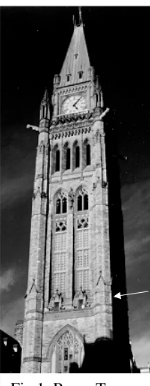
Examples will be given from a long-term program to monitor the performance of the exterior masonry on the Peace Tower (Fig 1). This 92 m high tower, built between 1919-1927, is the most noticeable structure on Parliament Hill in Ottawa. The exterior walls are plain concrete faced with sandstone masonry (the masonry acted as the outer formwork). Walls are 1.8 m thick at the base and narrow to 0.6-0.9 m below the clock level. Figure 2 shows a cross-section about one-third of the way up. The tower exhibited serious distress in the form of cracking and mortar deterioration mainly caused by frost action. Ottawa climate is severe in terms of freeze-thaw cycles, freezing rain, and mild winter temperature that necessitate the use of de-icing salt. A major conservation project was completed in 1996. It included grouting between the stone and concrete, repointing all the mortar joints, repairing stones and improving water shedding details.
1
Institute for Research in Construction, National Research Council, Ottawa K1A 0R6, Canada
2
Heritage Conservation Program, Public Works & Government Services Canada, Ottawa K1A 0M5, Canada
Proceedings of the 12th International Brick/Block Masonry Conference, Madrid, Spain, June 25-28, 2000, Vol. II, PP. 1221-1233
2
N
Fig 2 Cross-section at Refuge level (see arrow in Fig 1).
MONITORING OBJECTIVES
Clear, well-defined objectives are needed to achieve a successful monitoring program. Monitoring may be carried out for the following reasons:
• To understand the behaviour of buildings and as a check on theoretical predictions. The monitoring of actual performance while a building is in service can also ensure that the assessment of safety and serviceability is not solely based on prediction.
• Act as an early warning system to ensure the safety of the occupants and could feed into appropriate renovation and maintenance programs.
• Assess the impact of environmental factors on the durability and performance of the exterior envelope (this was the main objective of the Peace Tower monitoring).
• Assess the impact of major interventions (retrofit, re-insulation, renovation, etc.) or a change in use or occupancy (operating conditions, energy use, comfort, interior modernisation, etc.) on building envelope performance.
• In response to particular concerns.
APPROACH TO MONITORING 1. Initial Review
An initial review of the available information about the building under consideration is important. The following actions are recommended:
• Review of building construction history.
• Review of available condition assessments, intervention reports, and maintenance records.
• Walk-through inspection.
• Limited test openings for verifications (if needed).
• Limited measurements: indoor air temperature & relative humidity; surface temperatures; air pressure differences; moisture levels.
2. Define Objectives and Approach
The following are issues to be considered:
• Questions to be answered, hypotheses, parameters to be monitored, expected range in results.
• Scope of monitoring: short-term vs. long-term.
• Flexibility to amend the program as the monitoring is progressing.
• Deliverables (report, goals, client expectations).
performance following the completion of the conservation work. It will provide an early warning of future deterioration and help provide explanations for any deterioration.
3. Select Monitoring Locations
Determine building envelope component(s) to be assessed based on the analysis results of the background review (areas/issues of concern and hypotheses developed; exterior walls, foundation walls & slab, roof, junctions: wall-roof, wall-floor slab, wall-window/door, windows & doors, mechanical system).
Select representative sections of the building envelope for the measurements. Selection criteria may include:
• Expected worst conditions.
• Long term durability.
• Change of operating conditions, re-insulation, new cladding, interior renovation, improved comfort.
• Instrumentation (sensors, wiring, data acquisition system) should, where possible, not be visually intrusive, protected from interference, accessible and not interrupt the normal operation of the building.
• Some locations may not be accessible or may not be allowed by the building owner.
Monitoring is preferred to be non-disruptive so that the building envelope performance is not affected by the measurements that are made. Non-disruptive monitoring should allow:
• measurement sites to be returned to their original state after the measurements are completed.
• installation to be designed, where possible, for the easy removal of sensors for calibration, and retrieval of expensive sensors at the end of the monitoring.
• monitoring during normal building occupancy.
On the Peace Tower monitored locations were selected after reviewing the damage and deterioration and areas where wetting is likely to occur. There were also restrictions caused by access, and the need to keep the instrumentation and wiring on the exterior as inconspicuous as possible. For example, a grey plastic cover was put over shiny stainless steel displacement sensors to make them less visible. Sensors were concentrated at one and two thirds of the height and within the roof space. There is also a weather station at the top of the tower.
4. Monitored Parameters
Design the measurement program based on the defined objectives. Field monitoring must cover as wide a range of climate as possible because the thermal, moisture, and air leakage performance of building envelope are dependent on ambient weather conditions. Monitoring should therefore take place over an extended period of time (at least one year; normally 18 to 24 months).
For the Peace Tower the monitoring program was designed for 20 years. Data collection started in August 1998. Monitored are interior and exterior environment conditions, moisture and temperature changes in the masonry, air pressure differences across the wall, movement across repaired cracks, and movement due to earthquake.
Examples of conditions monitored on the Peace Tower
Environmental conditions – exterior
A weather station located at the top of the tower measures:
• air temperature and relative humidity. From this the dew-point temperature can be calculated (condensation will occur on surfaces with temperatures below the dewpoint). The dewpoint is also an indication of the quantity of water in the air (useful for assessing moisture transport between different locations).
• wind speed & direction.
• rain; acidity of rain.
• solar radiation.
Environmental conditions – interior • air temperature and relative humidity.
• heating and cooling system supply temperature & relative humidity.
4
Building envelope • Thermal parameters
- temperature profile (gradient) across walls (including yearly temperature range). Indicates potential for drying and thermal movement.
- thermal bridge effects.
- thermal resistance of wall assembly and individual components.
- temperature measurements also give freeze-thaw cycles which indicate the potential for frost damage (cycles measured about different temperatures: 0, -2, -5°C, …water in smaller pores will freeze at lower temperatures than 0°C; salts will also lower freezing temperature). For the Peace Tower during the winter of 1998/99, the number of outdoor air freeze-thaw cycles about 0°C was 39. The freeze-thaw cycles on the surface of the masonry itself depended on orientation and wall thickness. At 23 m above ground level, four sides of the tower recorded 44, 32, 67 & 62 freeze-thaw cycles. The minimum air temperature over the winter was –28°C. No damage was observed except at the very bottom of the tower where deterioration of mortar and stone patching was observed. A water shedding detail directed water onto masonry (see Figure 3); the area is also subject to snow melt on the ground and contamination from de-icing salts.
Fig 3 Wetting of masonry caused by melting snow from gutter beside arch
• Moisture parameters (wetting from rain, melting snow & ice, condensation and water leakage) - surface moisture sensors show periods of wetting and drying.
- sensors within wall to indicate changes in moisture levels.
- pressure sensors measure differential air pressure across wall assemblies and components (e.g. air cavity within wall). This gives an indication of the potential for air leakage across the wall.
• Movement in the wall envelope
- movement between different wall components, or between wall and other building components. - movement across cracks (existing and repaired).
Overall building movement • Static movement – lateral deflection. – settlement.
• Dynamic movement
- response to wind, traffic, blasting and earthquakes. - changes in dynamic properties with time.
- natural period of vibration and mode shapes.
5. Instrumentation
Careful selection of the monitoring equipment is needed in order to avoid unnecessary increase in cost resulting from unneeded measurements. Collected data could also be overwhelming at the analysis stage (for the Peace Tower over 170 sensors were installed). Therefore, for the purpose of selecting instrumentation, the following items should be considered:
• list purpose of each sensor in terms of objectives.
• select reliable equipment since it will reduce the time and cost required for maintaining them especially if they are in inaccessible or difficult to reach locations. Sensors located on the exterior should also withstand exposure to the weather. On the Peace Tower the thermocouple wires had teflon sheathing. Displacement sensors were made of stainless steel and water-resistant.
• duplicate some sensors as a check and where they are critical to the outcome. Examples of typical instrumentation used in the Peace Tower are:
Temperature
• Shielded type T thermocouple wire was used to reduce any electrical noise superimposed on the thermocouple signal in the field. Accuracy ±0.5°C.
Relative humidity
• Polymer resistance relative humidity sensors, which provide a continuous electrical output suitable for remote, long, term monitoring (accuracy ±1 to ±3%).
Air pressure
• Differential air pressure
- low pressure differential (e.g. indoor air to wall cavity air), range: ±125 Pa
- high pressure differential (e.g. indoor air to outdoor air), range: ±650 to ±1000 Pa Surface wetting
Several sensors are used to detect wetting.
• Sensors based on an electrochemical cell containing two different metals, copper and gold, in an interlaced pattern plated onto an insulating substrate (Hechler et al 1990). When moisture condenses on the sensor it activates the cell, producing a small voltage. An alternative, not used on the Peace Tower, is an interleaved gold electrode (Norberg 1993). A fixed voltage is applied with alternating polarity. The resulting current is an indication of level of moisture (condensation, rain).
• Electrodes were also attached to small blocks of ceramic material attached to the surface. When the ceramic material becomes wet, its electrical resistance decreases.
• A rain gauge to monitor rainfall was installed as part of the weather station at the top of the tower. Specially constructed gauges, not used on the tower because of visibility, have been used to monitor wind driven rain on vertical wall surfaces (Saïd et al 1997a).
Moisture in the masonry
Moisture in a material such as masonry can be measured directly or indirectly. Moisture measurements are approximate but do give a good indication of wetting and drying patterns.
• Electrical resistance techniques:
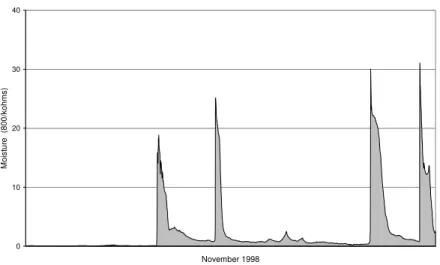
- stainless steel screws inserted in mortar joints detect moisture directly by measuring electrical resistance. Resistance will decrease as the moisture level rises. The magnitude of the resistance can vary between several hundred k-ohms (wet condition) to over 1 G-ohm (dry condition). Figure 4 shows an example of the sensor output.
- similarly electrodes were attached (glued) to small stone sensors inserted within holes drilled into the wall. The stones were made of the same material as the existing stone masonry. An alternative, not used here because of long term durability, are small wood sensors used as indirect moisture sensors by measuring the humidity levels within a material (Brandt et al).
6 0 10 20 30 40 November 1998 M o is tu re (800 /k ohm s )
Figure 4 Wetting of a mortar joint on east facing masonry
Heat flux
• Heat flux across a wall can be measured by heat flux sensors [Saïd et al 1997a]. One was installed in the Peace Tower to determine the thermal resistance of a section of the wall that was rebuilt to allow an elevator to be installed. The wall consists of an insulated steel frame with stone cladding (north wall section in Figure 2). Another was installed on a composite concrete/masonry wall section in order to use results to monitor changes in moisture level.
Solar radiation
• Pyranometers were installed to monitor solar radiation directly on the vertical wall surface. Movement (static & dynamic)
• LVDT displacement sensors, some with swivel end connections, were installed to check for potential movement across joints and former cracks in the masonry. Other types are also available: potentiometric & vibrating wire. So far no sign of cracks occurring at former crack locations.
• Electronic levels were installed at different levels to measure tilt of the tower due to environmental influences (the tower is built on bedrock therefore settlement is not a problem).
• Vibration sensors were installed at different levels to monitor movement by earthquake, wind and blasting (from construction work).
Data acquisition equipment
Typical requirements for the data logging system:
• Precision measurement, excitation power supply required by some sensors, and control capability.
• Measurement of resistance using alternating polarity.
• Rugged and expandable system; long-term reliability.
• Number of channels will depend on the monitoring requirements.
• Stand-alone operation option with battery backup.
• Remote programming and data retrieval using a modem.
• Use of single cable with nodes to reduce amount of wiring should be considered when the objective is to set-up an alarm system [Hutton 1996].
Three data loggers were used in the Peace Tower in order to reduce the length of wiring needed. Another data logger is used exclusively for the vibration sensors. All have battery backup and can be accessed by modem for data collection and program changes.
The time intervals for data recording will depend on the type of sensor. On the Peace Tower temperature, displacement and moisture sensors are monitored at minute intervals. Hourly averages are recorded except for the moisture sensors averaged every 15 minutes (output can also include max/min and standard deviation). Differential pressure sensors are recorded as 10 and 60 minute averages of 1 second readings. The seismometers only record when a vibration sensor monitors an acceleration greater than 0.5% of gravity, or 0.1% for the sensor in the basement.
6. Debugging/Commissioning of Monitoring System
After completing with installation of the instrumentation, a debugging phase is necessary. In this phase, measured data is analyzed in order to ensure that the measurements are performing as anticipated. This checks the proper installation and operation of sensors and the appropriateness of the measurement locations (additional sensors and/or revision of measurement locations may be needed).
7. Data Processing and Analysis
The following are general notes regarding data processing and analysis:
• data is stored in two locations (one on a common disk accessible through a network, the other on CDs as a backup). A document listing the data sets is also kept on the common disk. Access through a network is useful as it allows several people to access the data. Analysis is by spreadsheet templates.
• need for data analysis programs to check all incoming data for anomalies or errors. Anomalies, errors and sensor malfunction need to be detected early (the cause may be difficult to assess at a later date). Such analysis programs are still in the development stage.
• develop programs to output the data in a format suitable for analysis and reports (e.g. use of spreadsheets to display results).
• conduct regular discussion sessions on the progress of monitoring.
• for the Peace Tower, a relational database is used to sort the data; for example, 6 million readings are obtained every year.
8. Periodic Building Inspection
• Periodic inspection of the building is recommended. Observing wetting patterns, deterioration and surface cracking will complement the monitored data and may lead to changes in sensor locations.
• Final inspection should be conducted prior to the removal of sensors and terminating monitoring.
9. Reporting
• Periodic reporting (especially for long term monitoring) is important, as it will assure regular evaluation of the collected data. For the Peace Tower the plan is to produce a regular annual report.
• Proper documenting is required from the very start of the monitoring (e.g. equipment type, supplier, location, and calibration records).
CONCLUDING REMARKS
Monitoring building is an excellent means of determining performance in practice. Monitoring has a positive side effect because it ensures regular visual inspection of the building. Modern sensors and data-logging systems are becoming more reliable, easier to use and more economical. On the other hand, careful planning is needed to determine objectives, the best means of achieving them, and the best means of analysing the data. Time spent on this initially will more than pay for itself by time saved later on.
ACKNOWLEDGEMENTS
The authors would like to acknowledge the support of the Parliamentary Precinct Directorate of Public Works and Government Services Canada.
REFERENCES
Brandt E & Hansen M H. 1999. Measuring moisture content in wood with built in probes 20+ years experience. Durability of Building Materials and Components 8. Ed. M A Lacasse & D J Vanier. National Research Council Canada. pp 669-679.
Dunnicliff J. 1997. Systematic approach to planning monitoring programs using geotechnical instrumentation - an update. Geotechnical News. Sept 97. pp 36-46.
Hechler J J, Boulanger J, Noël D, Dufresene R & Pinnon C. 1990. A study of large sets of ASTM G84 time-of-wetness sensors. ASTM Spec Tech Pub STP 1000, Symposium on corrosion testing and evaluation. pp 260-278
Hutton T. 1996. Monitoring Britain’s heritage. Construction Repair. Vol 10, No 1. Jan/Feb 96. pp 41-42,44.
8 McKenna G. 1996. Planning geotechnical tests and investigations for analysis and presentation. Part 1. Geotechnical News. Dec 96. p 37-45.
Moore J F A, editor. 1992. Monitoring of building structures. Blackie / Van Nostrand Reinhold. 155 p Rossi P P & Rossi C. 1998. Surveillance and monitoring of ancient structures: recent developments. in Structural Analysis of Historical Constructions II. Possibilities of Numerical and Experimental Techniques. Eds. P Roca, J L González, E Oñate & P B Lourenço. CIMNE, Barcelona, Spain. pp 163-177
Norberg P. 1993. Evaluation of a new surface moisture monitoring system. Proc 6th Int Conf on Durability of Building Materials & Components. Japan. pp 637-646.
Saïd M.N.A., W.C. Brown, and I.S. Walker. 1997a. Long-term field monitoring of an EIFS clad wall, Journal of Thermal Insulation and Building Envelopes, v 20, pp. 320-338.
Said M.N.A., W.C. Brown, C.J. Shirtliffe, A.H.P. Maurenbrecher. 1997b. Monitoring of the building envelope of a heritage house - A case study. Proc 7th Conf on Building Science and Technology, Toronto, Canada. pp. 243-260.