Control and Coordination of Supernumerary Robotic Limbs
Based on Human Motion Detection and Task Petri Net Model
The MIT Faculty has made this article openly available.
Please share
how this access benefits you. Your story matters.
Citation
Llorens-Bonilla, Baldin, and H. Harry Asada. “Control and
Coordination of Supernumerary Robotic Limbs Based on Human
Motion Detection and Task Petri Net Model.” Volume 2: Control,
Monitoring, and Energy Harvesting of Vibratory Systems;
Cooperative and Networked Control; Delay Systems; Dynamical
Modeling and Diagnostics in Biomedical Systems; Estimation and
Id of Energy Systems; Fault Detection; Flow and Thermal Systems;
Haptics and Hand Motion; Human Assistive Systems and Wearable
Robots; Instrumentation and Characterization in Bio-Systems;
Intelligent Transportation Systems; Linear Systems and Robust
Control; Marine Vehicles; Nonholonomic Systems, 21-23 October,
2013, Palo Alto, California, ASME, 2013, p. V002T27A006. © 2013 by
ASME
As Published
http://dx.doi.org/10.1115/DSCC2013-4083
Publisher
ASME International
Version
Final published version
Terms of Use
Article is made available in accordance with the publisher's
policy and may be subject to US copyright law. Please refer to the
publisher's site for terms of use.
CONTROL AND COORDINATION OF SUPERNUMERARY ROBOTIC LIMBS BASED ON
HUMAN MOTION DETECTION AND TASK PETRI NET MODEL
Baldin Llorens - Bonilla
Department of Mechanical Engineering Massachusetts Institute of Technology
Cambridge, MA 02139 [email protected]
H. Harry Asada
Department of Mechanical Engineering Massachusetts Institute of Technology
Cambridge, MA 02139 [email protected]
ABSTRACT
This paper presents a task model and communication method used to control and coordinate a wearable robot, termed Supernumerary Robotic Limb (SRL), with a human worker during the execution of a specialized task. When controlling a collaborative system like this, we need strong communication between the robot and its wearer in order to be able to coordinate their actions. We address the communication challenges between the human worker and the SRL by monitoring the worker’s actions with wearable sensors. Combining these wearable sensors together with a well defined task model allows the robot to act according to the wearer’s intent. The task model is structured using Coloured Petri Nets (CPN) due to the process’ deterministic and concurrent nature. We performed various tests in which the user had to execute a task while wearing the sensor suit. This data was used to establish the threshold values for our predetermined gestures and postures of interest. Detecting these postures and gestures are used to trigger task transitions in the CPN model. This allows the wearer to communicate his intentions effectively to the SRL and execute the task in a well-structured and coordinated manner with the SRL.
INTRODUCTION
Manufacturing industries are incredibly demanding making full automation a preference when it comes to repetitive and/or specialized task execution. However, there are such cases where a particular task cannot be fully automated. This can be the result of having a complex task or having to work in an environment where automation is not possible. The latter can be due to constrained space or complex environment-task relations. For tasks of this nature, Human – Robot Collaboration is a strong alternative that allows us to deal with
these problems through semi-automation while maintaining a high level of efficiency. Traditional human – robot collaboration systems consist of either exoskeletons [1] or of human – robot teams [2]. The first one aids the human by enhancing his or her physical attributes, such as strength and stamina, and the latter is able to help the human in his or her tasks; provided that it is able to accompany and coordinate with the main human worker [3-4]. These alternatives aid the human in very specific tasks aspects but do not increase an individual’s available skillset.
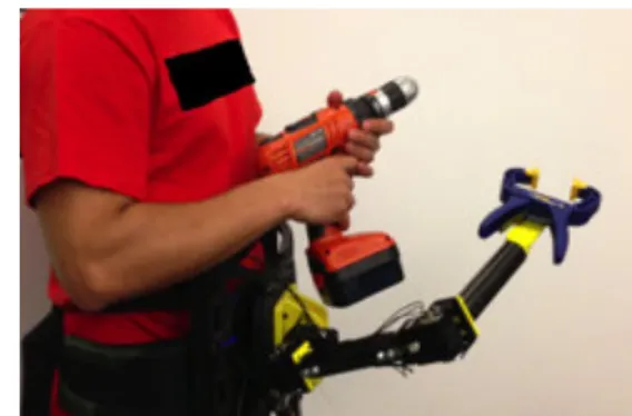
FIGURE 1. SIDE VIEW OF THE LIGHT WEIGHT SRL PROTOTYPE’S RIGHT ARM. ARMS ARE ATTACHED TO A BASE THAT GOES AROUND THE WEARER’S HIPBONE. THIS ENSURES THAT THE ADDITIONAL WEIGHT IS SUPPORTED BY
THE WEARER’S LEGS AND DO NOT PUT STRAIN ON THE BACK.
One particular field that has great abundance of such tasks is the Aircraft Assembly Industry. In this Industry, we have a constrained environment (plane fuselage) and a series of specialized tasks (wiring, drilling, fastening, cleaning, etc.) that have to be executed repetitively in different places across the fuselage. These tasks cannot be fully automated and some of them even require more than one worker to be successfully completed. In situations such as these, an exoskeleton that
1 Copyright © 2013 by ASME
Proceedings of the ASME 2013 Dynamic Systems and Control Conference DSCC2013 October 21-23, 2013, Palo Alto, California, USA
DSCC2013-4083
increases the human’s occupied space and only enhances his or her physical attributes cannot substitute the presence of a coworker. Collaborative robots, although they can share some task information and can interact with a human to perform a task, would need the capabilities to navigate through the environment and to coordinate with a dynamic environment [5]. This limits the robot’s design because it has to occupy the smallest space possible without limiting the human’s workspace. To address this issue, we propose a wearable robot, termed Supernumerary Robotic Limb (SRL) [6]. A lightweight prototype, intended mainly for tasks that do not require the SRL to bear high loads, is shown in Figure 1. Coordination is key when developing this system, as it will have a direct impact on the subject’s ability to achieve efficiently the desired task. We propose that communication between the SRL and the wearer be carried through intent detection. This is achieved by combining a sensor suit that monitors the wearer’s actions and gestures with a robust task model. By making the coordination between the SRL and the human worker as intuitive as possible we are able to present the SRL as an extension to the human body.
TASK
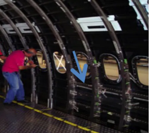
We focus on assembly tasks that require more than one worker to perform the job. In this paper we focus specifically on one exemplary task: fixing an intercostal on the fuselage. Figure 2 shows the environment in which this task is executed. Two trained workers simultaneously carry out this task. The task process goes as follows:
FIGURE 2. THE BLUE ARROW POINTS AT THE INTERCOSTALS THAT NEED TO BE FIXED AND DRILLED INTO THE AIRPLANE’S FUSELAGE.
1. The main worker picks up a beam (intercostal) and places it in the respective fuselage place.
2. Once the intercostal is in place, a coworker comes to fix it using a specialized gripper.
3. After the intercostal is secured, the main worker readies the drill to permanently fix it to the fuselage. 4. Once the drill is in place, the coworker then places a
vacuum beneath it. This is done to clean the carbon fiber composite that is expelled during the drilling process.
Once the task is completed, the workers recover all the used tools and return to a standby state. Following this standby state, the worker can proceed to other cleanup and assembly tasks as needed. In this paper we focus specifically in the task process up to step number 4. Our objective is to equip the lead worker with the SRL, enabling him to complete the task without the required additional aid of another worker. To do this effectively, the SRL must be able to coordinate with its wearer throughout the completion of the task.
This task that seems trivial for two human workers to execute becomes more complex as we incorporate the collaboration between the SRL and the worker. This task’s concurrent and non-deterministic nature makes coordination more challenging, because the worker has to deal with parallel tasks, resource allocation, and other task properties such as time delays and queues. We use Coloured Petri Nets (CPN) as the modeling technique to address these properties.
Coloured Petri Nets [7] combine graphical notation and basic primitives with the capabilities of a high level programming language to create a discrete-event model. These properties make CPN ideal for modeling systems where concurrency and communication play a vital role in the task’s process [8]. As mentioned previously, communication plays a vital role in CPN models. In this system, knowing the wearer’s intention and current actions is vital to the SRL because it identifies what is required to proceed through the model. In order to obtain that information we use an array of wearable sensors. By combining the CPN with the information gathered from these sensors, we are able to identify the worker’s intentions. High coordination will result in making the wearer faster and more accurate and precise. Previous work by our research team includes the mechanical effects of the added load when equipping the SRL [9] and the use of “teaching by demonstration” algorithms on simple sub tasks [6].
METHODOLOGY Task-Process Model
We intend to model the task process and resource allocation as similar as possible to a human’s. This will allow the SRL to act as a part of the human body and make the worker feel more comfortable when using the wearable robot. In order to do this we follow the following procedure:
1. The wearer identifies the task that needs to be completed.
2. The wearer identifies all the tools that are necessary to complete the task.
3. The human proceeds through the task model. To do this effectively the human must be able to communicate successfully with any aiding workers while keeping track of the environment.
Using CPNs to model tasks we take into account its two main components: graphics and mathematics. The graphical component of the CPNs is what allows us to separate visually the states from transitions that occur during the execution of a task. This part also defines the direction followed by the resources/tools when moving through the task process model. For this part, places (or states), transitions, arcs, and tokens (tools/resources) are represented as circles, rectangles, arrows, and dots, respectively. Figure 3 shows a simple representation of a basic petri net (PN). For this rudimentary PN, the location of the token indicates the state of the current task. Once a place has the necessary amount of tokens, we are able to move on to the next transition and the following place. When this happens, the used tokens are removed from their respective place and moved on to the next one, as indicated by the arc’s direction.
FIGURE 3. IN CASE A. WE HAVE THE INITIAL CONDITIONS WHERE THERE IS ONE TOKEN IN THE FIRST PLACE. SINCE THE TRANSITION ONLY REQUIRES ONE TOKEN WE MOVE TO CASE B. HERE, THE TOKENS USED TO ACTIVATE THE TRANSITION WERE REMOVED FROM THEIR ORIGINAL PLACE AND
MOVED TO THE NEXT PLACE.
This basic PN structure is not enough to describe complex tasks where different tools are needed for multiple tasks or to specify resource allocation during concurrent events. However, CPN have high level programing capabilities that we use to address such issues [8]. In order to properly model the task, we must define a finite number of places (or states) P, transitions
T, guard functions G, directed arcs A, arc expression functions E, colour sets Σ, coloured set functions C, typed variables V and
an initialization function I. Colour sets and functions, arc expressions, and guard functions will be directly responsible for managing how the resources and tools are used throughout the task process execution.
First of all, we give each token a colour to identify each particular tool or resource. We assign each token both a number and a string. The number is used in the mathematical expressions that determine which resource to use and the text is used to visualize the location of the tools and resources. Colours are defined as:
colset No = int; (1)
colset Re = string; (2)
colset NoxRe = product No * Re; (3)
This allows us to assign each token a number and a string element in that order. For example, we can assign one token with No = 1 and Re = “Human Right Arm”. Considering that different tools are used for specific tasks, the CPN must also be able to discern which tools are used for each particular task. Now that we are able to identify the tokens, we proceed to establish the constraint laws for the transitions. This is accomplished through the arc expressions and transition guards. Arc expressions are written right besides an arc and they determine which characteristics of the tokens in the place will be considered for the transition [9]. These must also be defined as variables. For our example in Figure 3 we define these variables as: colset status = bool; (4)
var n : No; (5)
var d: Re; (6)
var success : status; (7)
Transition guards establish certain criteria that must be true before the transition is able to take place. These are written inside brackets next to the corresponding transition, as shown in Figure 4.
FIGURE 4.SIMPLE EXAMPLES OF HIGH-LEVEL PROGRAMMING THAT IS
ACHIEVABLE THROUGH THE USE OF CPNS. THE NUMBER FOUR INSIDE THE GREEN SPHERE INDICATES THAT THERE ARE A TOTAL OF FOUR TOKENS IN
THAT PLACE.
In Figure 3, the tokens corresponding to all four arms (robot’s and human’s) are in the “Standby” place. In order to move on to the “Tool in hand” place, the tokens have to go through the “Pick up tool” transition. In order to go through this transition all the conditions in the input arcs must be fulfilled. This occurs when all the variables are bound (all necessary variables specified in the arc expressions can be matched with a respective token from the input place). In this particular case, we are specifying that only the human right hand must be used to pick up the tool. This means that we constrain the variable n to 1, and therefore the only token that is able to fire the “Pick up tool” is {n = 1, d = “Human Right Arm”}. Since we have at least one token that follows the guard’s constraint, we are able
3 Copyright © 2013 by ASME
to fire the transition. Notice than after the transition is made, output arcs determine the token distribution based on the “Success” variable.
Wearable Sensors and Intent determination
As described in the previous section, we are able to model the task process of specialized drilling through the use of CPNs. This model is composed of places (states) and transitions that are linked together through arcs and described by arc expressions and transition guards. Due to the fact that the allocation of tokens is determined by the output arc expressions we need a way of monitoring the task and generate the respective indicators. Since we are dealing with a human – robot collaborative system, we can make use of the fact that for this particular task, the human is able to monitor all the tasks outputs and is able to determine whether it was completed or not. We are able to obtain such information from the human by monitoring his actions and detecting certain gestures.
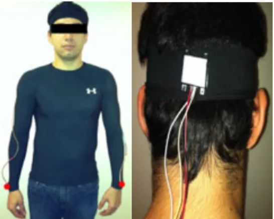
FIGURE 5. THE SENSOR SUIT HAS INERTIAL MEASUREMENT UNITS IN THE RED LOCATIONS: ONE ON THE BACK OF THE HEAD AND ONE IN EACH WRIST
(A RED DOT IS USED IN THE LEFT PICTURE TO LOCATE THE IMUS).
In the beginning stages of this project we detect certain predetermined gestures that the human normally uses to communicate with a fellow worker. This could be the case of a slight shoulder shrug or a nod. In order to monitor the wearer’s motions we equip him with an array of wearable sensors that are part of a sensor suit. The first prototype is shown in Figure 5. In this first prototype we use inertia measurement units (IMUs) located in the wearer’s wrists and back of the head.
For this preliminary study we focus on detecting a nodding gesture and the posture that corresponds to holding the intercostal in place and readying the drill. The assemblage demands that the human arms be in use every time the robot is required to perform a certain action. We also consider that the workers prefer to use their heads to communicate with others when both their hands are busy and they are operating within a noisy environment. These conditions are presumed in order to simulate the working environment of an aircraft assembly plant.
We performed two experiments where the test subjects had to follow the procedure explained in the Task section of this
paper. These experiments consisted of two parts, the first focused on the nodding and the second on integrating the nodding with posture detection for the completed task. The first experiment consisted of having the test subject sit down and nod when indicated by a LabView VI (Figure 6). This first experiment lasted 30 seconds and had from 4 – 5 nods.
FIGURE 6. LABVIEW VI USED TO MEASURE GYRO AND ACCELEROMETER RAW DATA (TOP AND BOTTOM GRAPH RESPECTIVELY) WHEN THE TEST
SUBJECT NODS.
Nod indications were generated randomly, with a minimum time separation of 3 seconds and up to a maximum of 5 nods per test. For the second experiment we used the fuselage mockup shown in Figure 7. This experiment consisted of two parts. The first one was to pick up the intercostal shown in Figure 7 (blue arrow) and to set it up in the fuselage. After the intercostal is placed correctly on the fuselage, the test subject nods. The second part consisted of picking up a drill and placing the drill bit by one of the already fixed intercostals.
FIGURE 7. SHOWS THE TESTBED THAT WAS USED TO RECORD THE TRAINING DATA AND TEST THE PETRI NET CONTROL SCHEME. THE BLUE ARROW
INDICATES THE INTERCOSTAL THAT MUST BE PLACED IN THE SAME MANNER AS THE ONE INDICATED BY THE RED ARROW.
The second experiment lasted 30 seconds and consisted of picking up the intercostal, nodding and readying the drill from 4 - 5 times. Each experiment was repeated 5 times with 5 different test subjects. We define a vector X that contains all the recorded data points such that
X =
{
x
1x
2! xi
}
T
where !! are the recorded data vectors. This data is obtained
from each IMU. Each IMU provides us with Gyro and Accelerometer readings. This is also shown in Figure 6. The signals used to determine the threshold values for the nod detection are the Z and Y gyro readings. These were chosen so that we could detect the nodding action regardless of the posture of the wearer. Accelerometer and Euler Angle readings were discarded as they vary with the head’s orientation. In our case we consider any point within the 20% of our maximum velocities for each nodding action in the training set. This constraint prevents us from giving false positives when the worker performs an unsecure or slow nod.
For more complex posture – gesture combinations we can move from simple thresholds to the use of Support Vector Machines (SVM) classifiers [10]. This technique has been widely studied for pattern recognition of one or multiple categories [11-12] and for time-series data [13].
RESULTS AND DISCUSSION
Our nonhierarchical CPN model has the following places and transitions:
P = {t_and_r, b_in_p, fixed_b, d_in_p, v_in_p, task_end} T = {p_b, fix_b, p_d, p_v, drill}
Where t stands for tools, r for resources, b for beam, p for place, d for drill and v for vacuum. We define the set of colours:
Σ = {No, Re, NoxRe, status, Tools} Where
colset No = int; colset Re = string;
colset NoxRe = product No * Re; colset status = bool;
colset Tools = list NoxRe;
The Tools colour was chosen to be a list since it would simplify accessing a place’s tokens in situations where we would have more than one token. The initial conditions for the system are the tokens in the “t_and_r” place and are given by:
1`(1, “HRA”)++ 1`(2, “HLA”)++ 1`(3, “RRA”)++ 1`(4, “RLA”)++
1`(5, “Gripper End effector”)++ 1`(6, “Vacuum End effector”)
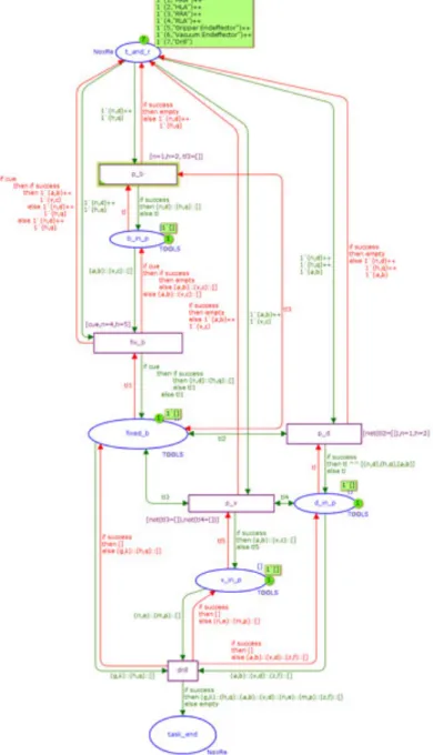
Where HRA, HLA, RRA and RLA stand for Human Right and left arm and Robot Right and Left arm respectively. The resulting structure for the CPN model is shown in Figure 9.
FIGURE 9. CPN MODEL FOR THE ASSEMBLY TASK.
In order to examine this model we use the state space method. This method consists of exploring all possible transitions and resource allocation that can occur from each place. This is done by representing each marking (reachable state by the whole CPN) as a node and then mapping its transition to previous and successive nodes. Each of the arrows that leave a node represents a binding variable that is used to reach that marking. This allows us to check the system for token duplication, misplacement, starvation and all the possible ending states for our CPN. Using the simulation software CPN tools we are able to map out the state space for our task process model (Figure 10).
5 Copyright © 2013 by ASME
FIGURE 10. WE CAN SEE FROM THE DIAGRAM THAT DUE TO OUR TASK SPECIFICATIONS, WE ARE ABLE TO MODEL THE ENTIRE TASK WITH 7
REACHABLE CPN STATES AND ONLY ONE FINAL STATE.
Each node represents a possible state of the Coloured Petri Net. The number on top in Figure 10 is the number of the overall state. The numbers on the bottom of each state represent the previous and successive states. Node #1, for example, gives the following information: this is the first system overall state of the task model, it can only be predeceased by one state and has two possible outcome states. In this case, the possible previous state is itself and the possible outcomes of this state are to either remain in the same state or proceed to the next state. The later would happen after firing the first transition.
After carefully checking each of the state space nodes we can conclude that the task is executed without any token duplication, misplacement or starvation and has only one possible ending state.
Using this nonhierarchical CPN to model a particular task also helps us organize the SRL’s task database. This particular task can be portrayed as a module in a hierarchical CPN (HCPN) that would be the SRL’s decision - making algorithm. Making the tools’ place the general starting point of the HCPN allows us to define tasks process models for each specialized task. These models become the HCPN’s modules, and the SRL can then make the decision of which action to perform based of the indicators that it receives from the environment and the wearer.
These indicators are obtained through the wearable sensor. Using the IMUs worn through the sensor suit we are able to extract the velocities and accelerations on the X, Y and Z direction and Euler Angles of the head, shoulders and arms. This information is used with two purposes: to estimate the human’s posture and space occupied by him or her, and to identify the wearer’s gestures.
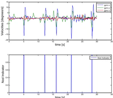
Additional experiments were conducted to test the threshold conditions for the nod action and the postures for a correctly placed intercostal and drill, in the same fashion as in the previous section. We are able to classify our sensor suit’s raw data based on the predetermined thresholds. The nodding detection results are shown in Figure 11. We can successfully detect 90% nods, and ignore feints as long as they don’t approach 80% of our maximum velocities from the training data sets. These results also apply to the posture of the wearer. The only difference is that for the posture we focused on the
Euler angles that are obtained through the use of the accelerometer readings. Once again, we were able to detect correct final posture on each of the validating experiments. By classifying this data as a Boolean variable we are able to integrate this directly with the CPN conditions and guards; which is then used to relay the human worker’s intention to the robot. The SRL then proceeds to execute the commands determined by the task’s dynamics.
FIGURE 11. DURING THIS TEST, THE WEARER NODDED FIVE TIMES. WE ARE ABLE TO DETECT NODDING USING A SIMPLE THRESHOLD CLASSIFIER. THE SAME METHOD IS USED FOR SENSOR READINGS FOR POSTURE DETECTION.
This algorithm works for simple gestures that can be linearly classified. These kinds of gestures, as mentioned previously, simulate coordination similar to that of working together with another human. To accomplish our goal of making the SRL feel like an extension of the human body we need to make this communication process more intuitive. For this we need to identify other signals and rely more on the wearer’s natural gestures while executing the task. A possible approach is to add force sensors in the safety gloves to monitor the worker’s grip pattern. Another approach may be the use of gaze tracking to give the SRL a means to share the same eyes as the human. In this scenario, a simple threshold technique to identify these complex indicators would not suffice. A stronger classifier, such as the Support Vector Machines, could be used address this issue.
CONCLUSION AND FUTURE WORKS
In this paper we show how CPNs can be used to effectively model specialized aircraft assembly tasks for a worker using wearable robotic limbs termed SRL. Using the State Space method we were able to analyze the task process’ resource and tool allocation, reachable states and end states. Through rigorous definition of each state and transition of the CPN we are able to obtain a model with minimal system states, perfect
0 5 10 15 20 25 30 35 −20 −15 −10 −5 0 5 10 15 time [s] Velocities [degrees/s] 0 5 10 15 20 25 30 35 0 0.2 0.4 0.6 0.8 1 time [s] Nod Indicator gyro x gyro y gyro z Nod Indicator
resource management and only one system end state, which corresponds to a completed task. This nonhierarchical CPN is a module that can be used in an overall HCPN in charge of the SRL’s decision - making process.
Combining our task model with the sensor suit allows us to use predetermined gestures and detected postures to relay the human’s intention to the SRL. This is observed as a Boolean indicator that leads the SRL into the system dynamics relevant to the determined next task. This coordination between the SRL and the human worker resembles the coordination between two workers.
In order to move towards perceiving the SRL as part of the human body we have to explore human behavior during aircraft assembly tasks. To do this, we need to increase the number and variety of sensors that monitor human behavior. In such case, the use of Support Vector Machines could help detect more complicated gesture – posture combinations. We will use this method to include more intuitive gestures as indicators in our CPN model. Lastly, we will evaluate how we can incorporate more human uncertainties in the CPN without affecting the outcomes of the State Space analysis. An example of such uncertainties is the fact that a human could make a decision to switch with the SRL and let it perform the drilling task while the wearer holds the vacuum beneath the drill.
ACKNOWLEDGEMENTS
This research’s primary sponsor is the Boeing Company.
REFERENCES
[1] Kousidou, S., Tsagarakis, N., Caldwell, D. G., and Smith, C., 2006. “Assistive exoskeleton for task based physiotherapy in 3-dimensional space”. The First
IEEE/RAS-EMBS International Conference on Biomedical Robotics and Biomechatronics, February, pp.
266-271.
[2] Hoffman, G., and Breazeal, C., 2004. “Collaboration in human-robot teams”. Proc. of the AIAA 1st Intelligent
Systems Technical Conference, Chicago, IL, USA.
September.
[3] Yamamoto, Y., Eda, H., & Yun, X., 1996. “Coordinated task execution of a human and a mobile manipulator”. In
IEEE Proceedings in International Conference on Robotics and Automation, Vol. 2, pp. 1006-1011
[4] Awais, M., and Henrich, D., 2010. “Human-robot collaboration by intention recognition using probabilistic state machines”. 2010 IEEE 19th International Workshop
In Robotics in Alpe-Adria-Danube Region (RAAD), June,
pp. 75-80.
[5] Fong, T., Thorpe, C., and Baur, C., 2003. “Collaboration, dialogue, human-robot interaction”. Robotics Research, 255-266.
[6] Llorens-Bonilla, B., Parietti, F., and Asada, H. H. (2012, October). “Demonstration-based control of supernumerary robotic limbs”. 2012 IEEE/RSJ International Conference on Intelligent Robots and Systems (IROS), pp. 3936-3942.
[7] Viswanadham, N., & Narahari, Y. (1987, March). “Coloured Petri net models for automated manufacturing systems”. Proceedings of The 1987 IEEE International
Conference in Robotics and Automation, Vol. 4, pp.
1985-1990.
[8] Jensen, K., & Kristensen, L. M. (2009). “Coloured Petri Nets: modelling and validation of concurrent systems”, Springer, Chapter 1-7.
[9] Davenport, C., Parietti, F., and Asada, H., “Design and Biomechanical Analysis of Supernumerary Robotic Limbs”. Proc. Of The 2012 ASME Dynamic Systems and
Control Conference and 2012 Motion Vibration Conference, Ft. Lauderdale, Florida, Oct. 17-19, 2012.
[10] Theodoridis, S., & Koutroumbas, K. (1999). “Pattern Recognition”, Fourth Edition, Elsevier Inc, Chapter 3 pp. 119-142.
[11] Fung, G. M., and Mangasarian, O. L. (2005). “Multicategory proximal support vector machine classifiers. Machine Learning”, 59(1), 77-97.
[12] Huang, C. L., and Wang, C. J. (2006). “A GA-based feature selection and parameters optimization for support vector machines”. Expert Systems with applications, 31(2), 231-240.
[13] Köknar-Tezel, S., and Latecki, L. J. (2011). “Improving SVM classification on imbalanced time series data sets with ghost points”. Knowledge and information systems, 28(1), 1-23.
7 Copyright © 2013 by ASME