Publisher’s version / Version de l'éditeur:
Vous avez des questions? Nous pouvons vous aider. Pour communiquer directement avec un auteur, consultez la première page de la revue dans laquelle son article a été publié afin de trouver ses coordonnées. Si vous n’arrivez pas à les repérer, communiquez avec nous à PublicationsArchive-ArchivesPublications@nrc-cnrc.gc.ca.
Questions? Contact the NRC Publications Archive team at
PublicationsArchive-ArchivesPublications@nrc-cnrc.gc.ca. If you wish to email the authors directly, please see the first page of the publication for their contact information.
https://publications-cnrc.canada.ca/fra/droits
L’accès à ce site Web et l’utilisation de son contenu sont assujettis aux conditions présentées dans le site LISEZ CES CONDITIONS ATTENTIVEMENT AVANT D’UTILISER CE SITE WEB.
Laboratory Memorandum (National Research Council of Canada. Institute for
Marine Dynamics); no. LM-1996-01, 1996
READ THESE TERMS AND CONDITIONS CAREFULLY BEFORE USING THIS WEBSITE. https://nrc-publications.canada.ca/eng/copyright
NRC Publications Archive Record / Notice des Archives des publications du CNRC :
https://nrc-publications.canada.ca/eng/view/object/?id=d07e2e4f-cfc8-4d57-9926-1dd9831815fa
https://publications-cnrc.canada.ca/fra/voir/objet/?id=d07e2e4f-cfc8-4d57-9926-1dd9831815fa
NRC Publications Archive
Archives des publications du CNRC
For the publisher’s version, please access the DOI link below./ Pour consulter la version de l’éditeur, utilisez le lien DOI ci-dessous.
https://doi.org/10.4224/8896085
Access and use of this website and the material on it are subject to the Terms and Conditions set forth at
Comparisons of model experiments to determine survivability limits
after damage on roll-on roll-off passenger ferries
Institute for Ocean Technology
Institut des
technologies oc ´eaniques
Laboratory Memorandum
LM-1996-01
Comparisons of Model Experiments to Determine
Survivability Limits After Damage on Roll-on Roll-off
Passenger Ferries
C. Smith
March 1996
Smith, C., 1996. Comparisons of Model Experiments to Determine Survivability Limits After Damage on Roll-on Roll-off Passenger Ferries. St. John's, NL : NRC Institute for Marine Dynamics, LM-1996-01.
■"*■
Canada
National Research CouncilCanada
Conseil national de recherchesInstitute for Marine Institut de dynamique
Dynamics marine
u
COMPARISONS OF MODEL EXPERIMENTS
TO DETERMINE SURVIVABILITY LIMITS AFTERDAMAGE ON ROLL-ON ROLL-OFF PASSENGER FERRIES
LM-1996-01
U
Claire Smith
March 1996
REPORT NUMBER
LM-1996-01
NRC REPORT NUMBER DATE
March 1996
REPORT SECURITY CLASSIFICATION
Unclassified
DISTRIBUTION
Unlimited
TITLE
Comparisons of Model Experiments to Determine Survivabiiity Limits after Damage on Roll-on Roll-off Passenger Ferries
AUTHOR(S)
Claire Smith
CORPORATE AUTHOR(S)/PERFORMING AGENCY(S)
Faculty of Engineering
Memorial University of Newfoundland
PUBLICATION
Workterm report __
SPONSORING AGENCY(S)
Institute for Marine Dynamics National Research Council
IMD PROJECT NUMBER
743 NRC FILE NUMBER KEYWORDS ro-ro / ferries PAGES 11, Apps. A-B FIGS. 10 TABLES 6 SUMMARY
This report describes a review of model experiments carried out in support of the IMO panel
of experts on Ro-Ro Safety.
address National Research Council Institute for Marine Dynamics P. O. Box 12093, Station 'A1 St. John's, Newfoundland, Canada A1B3T5
LM-1996-01
TABLE OF CONTENTS
LIST OF TABLES AND FIGURES v
1.0 SUMMARY.... 1
2.0 INTRODUCTION 1
3.0 MODEL DESCRIPTIONS 2
4.0 UNITED KINGDOM AND SCANDINAVIA 2
4.1 Description of Model Ferry 2
4.2 Model Test Conditions 3
4.3 Discussion of Results 3
5.0 ITALY (MNF) 3
5.1 Description of Model Ferry 3
5.2 Model Test Conditions 4
5.3 Discussion of Results 4
6.0 ITALY (CONFITARMA) 4
6.1 Description of Model Ferry 4
6.2 Model Test Conditions 5
6.2 Discussion of Results 5
7.0 JAPAN 6
7.1 Description of Model Ferry 6
7.2 Model Test Conditions 6
7.3 Discussion of Results 6
8.0 SPAIN 7
8.1 Description of Model Ferry 7
8.2 Model Test Conditions 7
8.3 Discussion of Results 8
9.0 SCANDINAVIA 8
9.1 Description of Model Ferry... 8
9.2 Model Test Conditions 9
9.3 Discussion of Results 9
10.0 CONCLUSION 10
11 .0 REFERENCES
Appendix A: SOLAS 90 Model Test Conditions
Appendix B: Bibliography
LIST OF TABLES AND FIGURES
Tables United kingdom and Scandinavian Model Particulars 1
Italian MNF Research Model Particulars 2
Italian CONFITARMA Model Particulars 3
Japan Model Particulars 4
Spain Model Particulars 5
Scandinavian Model Particulars 6
Figures Results of Capsize Boundary Tests (Model 1), UK. and Scandinavia ... 1 Results of Capsize Boundary Tests (Model 2), UK. and Scandinavia ... 2 Description of Damage Cases, Italian MNF Research Model 3 Longitudinal View and Main Deck, Italian CONFITARMA Model 4 Overview of Japanese Ship Research Institute Model 5 Graph of GZ Curves With Water on Deck With GM=3.12m, Ship Research
Institute, Japan 6
Model Arrangement of Ferry, Spain 7
Dependence on Sea State with Significant Wave Height as the Independent
Variable, Spain
.."
8-10
COMPARISONS OF MODEL EXPERIMENTS TO DETERMINE
j
SURVIVABILITY LIMITS AFTER DAMAGE ON ROLL-ON ROLL-OFF
- PASSENGER FERRIES
; ! 1.0 Summary
The following report summarizes different model experiments performed by ; i countries around the world. The tests were performed in 1995 to observe stability
^
and survivability of ro-ro ferries after damage has occurred. The results of the
tests are useful for the International Maritime Organization, as they are eager to set new regulations to ensure the safety of passengers and crew.
Descriptions of models built by countries who participated in the model testing i i are outlined below. The model test conditions each country used are described in
U
Appendix A. Comparisons are made between the results of the tests carried out
by the different institutions and a brief summary outlining the models'
, performances in significant waveheights is presented at the end of the report. 2.0 Introduction
M
In the past year, extensive research has been carried out concerning survivability
limits after damage on roll-on roll-off passenger ferries. After recent tragic accidents of ferries capsizing, the International Maritime Organization became
M
interested in finding out the causes of these accidents and how they might be
avoided in the future. Many tests and experiments have been executed using model ships in several countries around the world.
I i
^
The International Maritime Organization selected a group of thirty or more Ocean
Engineering Researchers and Naval Architects to form a Panel of Experts. This
!
panel was created to propose new regulations to amend SOLAS 90 (Safety of
- Life at Sea). The new regulations must ensure adequate stability and
survivability and need to be thoroughly reviewed and tested as the lives of many
passengers and crew are at risk.
* i1
Countries around the world, such as the United Kingdom, Norway, Sweden, \ Finland, Denmark, Japan, Italy and Spain received the proposed amendments
^
from the Panel of Experts. Participants built models and performed test and
evaluation and analysis followed. This new information could then serve as a j guide in formulating the new regulations based on all the models1 performances
U
in the SOLAS 90 conditions.
It should be mentioned as well that Canada did participate in the model testing.
U The Institute for Marine Dynamics in Canada performed tests on a model ro-ro
ferry and obtained experimental data to study patterns and performance after damage had occurred. The data obtained from the tests was considered by the
J Panel of Experts due to the interest in freeing ports on ro-ro ferries. The model
not be applied in determining the SOLAS 90 regulations. Further information is
available in Reference [1]. 3.0 Model Descriptions
Models built should have represented the actual ship for the internal and external
arrangements, including the damage spaces. The length between perpendiculars was to be at least three meters and the hull of the model was to be thin enoughin areas where this feature had influence on the results. Scaling of the radius of
gyration in roll and pitch motions and wave heights should have beenrepresented properly. Draft, trim, heel and center of gravity should have
represented the worst damage case. Watertight bulkheads and other main design features should have been modeled to represent the actual ship.
The model test conditions were proposed by the Panel of Experts and are
outlined in Appendix A.
By evaluating certain characteristics of the tests, such as amount of water on deck, number of times capsizing occurred, stability control, and amount of
freeboard, the research institutes that performed the tests were able to submit
this data collected to the Panel of Experts. They will distinguish new regulationsbased on the models and the test results. 4.0 United Kingdom and Scandinavia 4.1 Description of Model Ferry
Marine Safety Agency and Joint North West R & D Project [Reference 2], built two ferry models used for testing stability and survivability after damage. The first model represented a centrecasing design and was also tested as sidecasing and open deck configurations. The second model had a different hull configuration, and possessed improved stability characteristics and freeboard in the damaged condition. It was tested as centrecasing and sidecasing designs, as well as having an open deck configuration. The various ship parameters are given in
table 1.
Table 1: Principal particulars (Marine Safety) Scale ratio Ship length (Lpp) Breadth (B) Draught (T) Displacement Freeboards (m) Shipi 1:42.033 131 m 26.0 m 6.1 m 12200t 0.2/0.6/1.1 Ship 2 1:34.667 130 m 25.5 m 5.75 m 11738t 0.5/1.0/1.9
LM-1996-01
4.2 Model Test Conditions
The model was free to drift in beam seas and tested in periods of 30 to 60
minutes in equivalent scale time. The midship, forward and aft damage situations were tested in long crested waves, having heights ranging from 1.0 to 7.0
meters. The water on deck and vessel motions in six degrees of freedom were measured and recorded. Capsizing boundaries were also investigated by testing intermediate wave heights.
4.3 Discussion of Results
The results of the tests performed on the model used by Marine Safety Agency and Joint North West R & D Project agreed relatively well with the rule proposal. The amount of water on deck (approximately 1000 tonnes at 530 seconds) related to the allowable amount proposed by the regulations. Researchers
concluded that by entering curves at the GM value corresponding to the SOLAS
90 requirements, the limiting wave height for vessels with residual freeboards in the range 0.2 and 0.6 m after damage is 1.0 -1.5 m, thus confirming the Panel of
Experts1 proposal that the SOLAS 90 standard is adequate in significant wave heights up to 1.5 m. The results of the capsize boundary test for the first model tested are shown in figure 1.
The Marine Safety Agency also concluded that sidecasing vessels have enhanced survivability in waves compared with centrecasing vessels. The capsize boundary tests for the second model tested are shown in figure 2. Data collected proves that forward damage results in less water ingress, allowing the vessel to survive in more severe seas. Also, capsize limits were not very
sensitive to the size of the damage opening. 5.0 Italy (MNF)
5.1 Description of Model Ferry
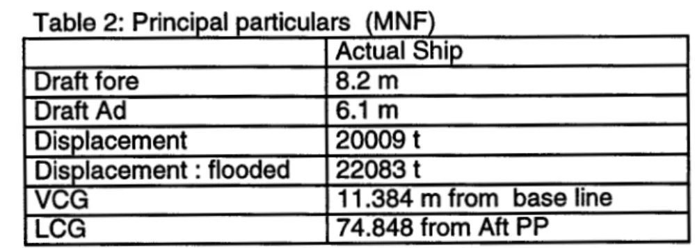
A model built in Italy by MNF Research [Reference 3], had several characteristics that are important to mention. The ship model was characterized by one
compartment subdivision, along with main transversal watertight bulkheads at seven locations on the main ro-ro deck. Below the main ro-ro deck, there were six partial transverse watertight bulkheads. Damage was located across two wing tanks on each side of the model below the bulkhead deck and four double
bottoms. The residual freeboard was 0.98 meters and the GZ-area was 0.0418
meters radians in worst damage case. The various ship parameters are given in
Table 2: Principal particulars (MNF) Draft fore Draft Ad Displacement Displacement: flooded VCG LCG Actual Ship 8.2 m 6.1 m 200091 220831
11.384 m from base line 74.848 from Aft PP
I I
5.2 Model Test Conditions
At MNF Research, tests were performed on the model in various sea states. The model was tested in two trim conditions: the first was at a normal trim in full load condition, worst damage case, and the second was at an even keel, same full load displacement, worst damage case. The ship model motions were recorded and analyzed while the ship model was drifting freely, facing the waves. Twenty probes were installed on the main ro-ro deck to record the level of water
accumulated. Also, different mean values of accumulated water heights obtained from the post analysis of probe signals were considered.
5.3 Discussion of Results
In all tested conditions, the ship model used by MNF research, showed good seakeeping performance. The speeds and accelerations of pitch and roll motions were at low values. By increasing the damaged side residual freeboard, water could reach the opposite side of the model due to the absence of obstructions on the deck. Residual freeboard increased from 0.5 m to 0.72 m due to heeling during the trial.
6.0 Italy (CONFITARMA)
6.1 Description of Model Ferry
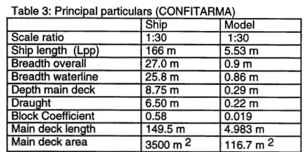
Another Italian research company called CONFITARMA (Confederazione Italiana Armatori) built a model to test stability and survivability after damage [Reference 4]. The model did not contain any subdivisions on the ro-ro main deck. Two compartments below the main deck were flooded through an opening on the starboard side representing the worst damage case. The side tank and double bottom were also damaged. The port side tank was flooded through the double bottom whereas the tank above the double bottom was intact. The model was built using wood with fiber glass reinforced plastic or aluminum plates placed in compartments to keep a thin shell plating. The model was fitted with two
propellers and shafts, rudders and bilge keels. The parameters of the model and ship are given in table 3. Figure 4 shows the longitudinal view and the main deck
LM-1996-01
Table 3: Principal particulars (CONFITARMA) Scale ratio
Ship length (Lpp) Breadth overall Breadth waterline Depth main deck Draught
Block Coefficient Main deck length Main deck area
Ship 1:30 166 m 27.0 m 25.8 m 8.75 m 6.50 m 0.58 149.5 m
3500 m 2
Model 1:30 5.53 m 0.9 m 0.86 m 0.29 m 0.22 m 0.019 4.983 m116.7 m2
6.2 Model Test Conditions
The model used by CONFITARMA was exposed to long crested, irregular seas and freely drifted approximately parallel to the wave crests with the damage on
the starboard side facing the waves. In order for the waves to become constant in height and speed, it was necessary to wait a few seconds until the sea state
was completely uniform before measurements could be taken. The model ran over a time corresponding to half an hour in full scale time (time scale 1:5.477). The sea states used were defined by the significant wave heights having a range
from 1.5 m to 4.0 m and their modal period having a range from 4.90 s to 8.00 s.
6.3 Discussion of Results
The results obtained by CONFITARMA in Italy, were very positive and agreed relatively well with the rule proposal. Several observations that follow are worth
noting. The rolling motion of the model was not symmetrical about zero due to
water accumulation on the ro-ro main deck opposite the damage hole. For lateral acceleration, again, the rolling motion was not symmetrical due to the gravity component when heeling occurs and to the relative motion in front of the opening. The residual stability due to SOLAS 90 and forward trim stopped the
accumulation of a larger amount of water on the ro-ro main deck.
Reducing the GM to 1.2 m with the ship trimmed on even keel in the damaged condition led to higher freeboard and metacentric height due to the wider
waterline at the stern. This reduction in GM had no significant effect on behavior because the freeboard became so high that only a small quantity of water
appeared. The buoyancy loss in the forebody caused a forward trim, which prevented the accumulation of a larger amount of water on the ro-ro main deck. Due to the stability, the small amount of water did not cause any significant
7.0 Japan
7.1 Description of Model Ferry
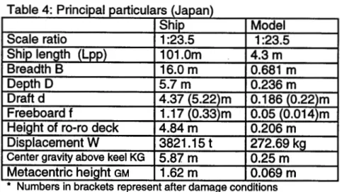
Model tests were carried out by the Ship Research Institute of Japan [Reference 5]. The model tested had a sidecasing configuration, without any barriers or
centrecasing on the ro-ro main deck. The model was tested with a two
compartment damage condition, and a damaged freeboard of 40 centimeters at the opening. The parameters of the model and ship are given in table 4. An
overview of the model is shown in figure 5. Table 4: Principal particulars (Japan) Scale ratio Ship length (Lpp) Breadth B Depth D Draft d Freeboard f
Height of ro-ro deck Displacement W
Center gravity above keel KG
Metacentric height gm Ship 1:23.5 101.0m 16.0 m 5.7 m 4.37 (5.22)m 1.17(0.33)m 4.84 m 3821.151 5.87 m 1.62 m Model 1:23.5 4.3 m 0.681 m 0.236 m 0.186 (0.22)m 0.05 (0.014)m 0.206 m 272.69 kg 0.25 m 0.069 m
* Numbers in brackets represent after damage conditions
7.2 Model Test Conditions
The model used by the Ship Research Institute of Japan, with a certain GM value and freeboard, was placed with the damage opening facing irregular waves 4 meters in height for 30 minutes in actual ship time. The amounts of water accumulated on the ro-ro deck and heeling patterns of the model were measured. Tests were repeated with different wave trains and GM damaged values. Further tests were completed using the same model with centrecasing present. No transverse barriers were present on the ro-ro deck.
7.3 Discussion of Results
The Ship Research Institute of Japan made a significant observation that the water depth criterion of 50 centimeters was too much for the model and did not reflect the physics of capsizing. By observation, the largest GM damaged
condition did not meet the requirements by calculation of 50 centimeters of water on the deck specified in the regulations. Figure 6 shows the GZ curves for a damaged model with a metacentric height of 3.12 meters and various amounts of
water on the ro-ro main deck. The curves clearly show how 50 centimeters of water on the ro-ro main deck does not meet adequate standards for survivability.
LM-1996-01
By performing other tests, the amount of water for the least freeboard condition and the high sea condition of 4 m wave height should be 12 centimeters.
The Institute of Japan also concluded that their model, along with many other ro-ro ships complying with the regulation specified, will be able to demonstrate their survivability by model tests carried out, even if the calculation with the water on the ro-ro deck may indicate otherwise. Ro-ro ships capsize because of
insufficient damage stability and not of accumulated water on the ro-ro deck. Researchers of Japan concluded that it is important to have a large enough
stability margin to provide safety of ro-ro ferries. 8.0 Spain
8.1 Description of Model Ferry
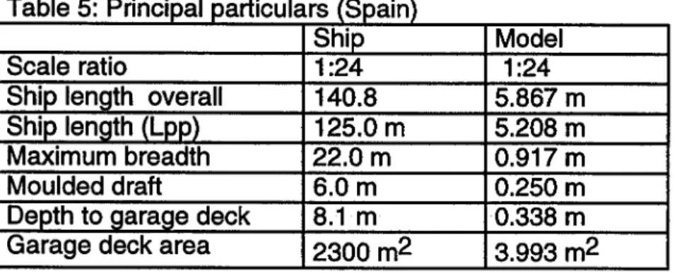
In Spain, CEHIPAR (Canal de Experiencias Hidrodinamicas de El Pardo), built a model based on a Spanish ferry vessel [Reference 6]. It was made using wood
and had a rudder and bilge keel reproduced from the actual ship. The model was
loaded to achieve different residual freeboards with an upright and even keel after damage conditions. To support varying ballast weights, the model contained four holds and reserve buoyancy was placed on the upper deck to prevent the model from completely capsizing. A garage deck was reproduced at 8.1 meters over the baseline without any obstruction, casing or trunks. Damage was near amidships on the starboard side. A vertical extension was produced from the bottom to the upper deck that produced flooding of the main engine room and the auxiliary machinery room. The double bottom was not flooded. The parameters of the model and ship are given in table 5. A model arrangement is shown in
figure 7.
Table 5: Principal particulars (Spain) Scale ratio
Ship length overall Ship length (Lpp) Maximum breadth Moulded draft
Depth to garage deck Garage deck area
Ship 1:24 140.8 125.0 m 22.0 m 6.0 m 8.1 m
2300 m2
Model 1:24 5.867 m 5.208 m 0.917 m 0.250 m 0.338 m3.993 m2
8.2 Model Test Conditions
CEHIPAR's model based on the Spanish ferry was tested in nine different
loading conditions to study the influence of residual freeboard and stability in the ship's behavior after damage. The loading conditions were combinations of three residual freeboards at the damage and three effective metacentric heights after damage. Loading conditions were such that the ship would stay upright at an
even keel after damage. For each loading condition, the model was subjected to irregular, long crested seas corresponding to the wave spectra with three
different significant wave heights. The model was parallel to the wave crests and the damaged side (starboard) was facing the incoming waves. The model was free to drift and could move in six degrees of freedom. The data acquisition
started after the wave pattern was fully developed.
8.3 Discussion of Results
Results obtained from experiments performed on a model ship in Spain agreed relatively well with the regulations proposed. In all experimental cases, with symmetrical flooding, the model tended to heel to the side opposite the incoming waves thus increasing the real freeboard at the damaged side. The heeling increased progressively until the freeboard at the damage was large enough to avoid further ingress of water. The amount of water accumulated on the garage deck for the waves of 2.75 and 4 meters significant wave height was very similar to that given by the formula of the Panel of Experts. Figures 8 to 10 illustrate the dependence on sea state where significant wave height is the independent variable. With water on deck, the model, with a GM as required by SOLAS 90 or higher, was able to withstand waves up to 4 meters in height with no capsizing. CEHIPAR in Spain did observe that the theoretical calculations of static stability did not take into account any contribution of the hull forms over the garage deck. Researchers thought the calculations of the hull forms should be included
because they seem to have some contribution to the righting arm due to dynamic effects.
9.0 Scandinavia
9.1 Description of Model Ferry
Tests performed by several countries including Denmark, Finland, Norway and Sweden, used a model to detect the required heights of transverse bulkheads on a ro-ro main deck [Reference 7]. Two configurations of the model were tested; a centrecasing design and a sidecasing design based upon the same basic hull form and subdivision configuration. Two sets of transverse bulkheads were
present, subdividing the vehicle deck into three almost equal sections. The model also contained a hanging deck 45 meters long and 4.5 meters wide. Vessel
parameters are given in table 6.
Table 6: Principal particulars (Denmark, Finland, Norway, Sweden) Ship length overall
Breadth Draft Intact GM: centrecasing Intact GM: sidecasing Ship 130 m 25.5 m 5.75 m 2.5 m 2,1 m
LJ LM-1996-01
9.2 Model Test Conditions
^
The tested configuration built by several countries including Denmark, Finland,
Norway and Sweden, was presented against significant wave height in the range ! of 2.5 m to 5.0 m with a corresponding range of modal periods from 6.3 s to 9.0 '-"' s. Tests were performed to investigate the required height of transverse
bulkheads, the effects of lowering hanging decks down onto partial height transverse bulkheads, the effects of openings in centrecasing, the effects of — vessel heading and the effects of sidecasing height.
9.3 Discussion of Results
i J
Using centrecasing and sidecasing configurations, the tests performed by I Denmark, Finland, Norway and Sweden obtained some positive results in
^
relation to detecting adequate heights for transverse bulkheads on ro-ro main
decks. By performing several tests, the flaps on top of partial height bulkheads had a positive effect. By placing openings in the centrecasing, a positive effect in
J
prolonging the time before capsizing was significantly noticed. Changing the
heading by 30 degrees to 60 degrees reduced water ingress and water sloshing. Half height transverse bulkheads were more effective and the vessel survived in
LJ
significantly higher sea states. Increasing the damaged freeboard from 0 to 0.5
meters will have the positive effect of providing a better safety margin against capsize and increasing the GM will also give a better safety margin against
M capsize.
For sidecasing configurations, the researchers found that the sidecasing should M extend at least 2 decks up from the main vehicle deck. Hanging decks next to
^
sidecasing on top of 2.3 meter high transverse bulkheads will have a positive
effect by reducing overflow to adjacent compartments.
u
The results of the testing done by these four countries had some negative effects
as well. When testing partial height bulkheads, researchers discovered that water | tends to overflow into the adjacent compartments due to sloshing effects. With
^ partial height transverse bulkheads, water tends to overflow in the comer
between casing and bulkhead. If this problem is not taken care of by pumps, the model capsizes.
10.0 Conclusion
Safety and survivability are the most important factors while designing and fabricating ro-ro passenger ferry vessels. Research institutes that built and used models according to the proposed SOLAS 90 regulations have found that those regulations set are reliable and will guarantee the safety of ferry vessels after damage has occurred.
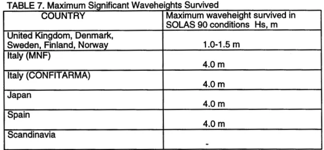
Table 7 illustrates the various maximum significant waveheights each model survived in SOLAS 90 conditions. The difference in results between the United Kingdom, Denmark, Sweden, Finland, and Norway and the rest of the group is most likely due to the actual physical shape of the model built for the testing and not due to the SOLAS 90 regulations followed. It is clearly shown that the
majority of the models survived waveheights of up to 4 meters and do provide safety by following the SOLAS 90 regulations. Perhaps further research and more experimental work are needed to determine the most feasible and safe
ferry design.
TABLE 7. Maximum Significant Waveheights Survived
COUNTRY
United Kingdom, Denmark,
Sweden, Finland, Norway
Italy (MNF)
Italy (CONFITARMA)
Japan
Spain
Scandinavia
Maximum waveheight survived in SOLAS 90 conditions Hs, m 1.0-1.5 m 4.0 m 4.0 m 4.0 m 4.0 m
-The analysis of the results of the many tests performed on models used all over the world will have significant importance to the design and manufacture of roll-on roll-off ferries in the future. The experimental data obtainedtrom the model tests will enable naval architects and engineers to improve the quality of ro-ro passenger ferries, increasing their survivability after damage has occurred.
LM-1996-01
11.0 References
1. D. Molyneux and D. Cumming, "A Model Experiment Technique for Predicting
the Capsizing of Damaged Ro-Ro Ferries", Institute for Marine Dynamics, NRC,
Canada, 1995.
2. "Consideration and Adoption of Amendments to the International Convention for the Safety of Life at Sea, 1974: Results of Model Tests Carried out by Marine
Safety Agency (UK) and Joint North West European R & D Project", submitted by Denmark, Finland, Norway, Sweden and the United Kingdom, International
Maritime Organization, November 6,1995.
3. G. Mezzani, M. Nattero, C. Falcone, "Memorandum: Italian Research on
Ro-Ro Passenger Ship", Studio Associato Di Ingegneria Navale, MNF, August 1995. 4. P. Blume, "Survivability Tests for a Damaged Ro-Ro Passenger Vessel", Hamburg Ship Model Basin, Confederazione Italiana Armatori (CONFITARMA), Rome, 1995.
5. "Intersessional Working Group on Ro-Ro Ferry Safety: Consideration of the proposed draft SOLAS amendments and related matters", submitted by Japan, International Maritime Organization, 1st session, October 5,1995.
6. "Consideration and Adoption of Amendments to the International Convention
for the Safety of Life at Sea, 1974: Seakeeping Tests of a Damaged Ferry
Vessel", submitted by Spain, Canal de Experiencias Hidrodinamicas de El Pardo,
International Maritime Organization, November 14,1995.
7. "Consideration of the Proposed Draft SOLAS Amendments and Related Matters: Technical Issues Under Draft SOLAS regulations 11-1/8 and 8-2",
required height of transverse bulkheads on the ro-ro deck, based upon model
tests performed under the project "Safety of Passenger/Ro-Ro Vessels",
submitted by Denmark, Finland, Norway and Sweden, International Maritime
Organization, October 6,1995.
2 3 GMI SOAS90GM Freeboard « 0.6nt GM< SOLAS90GM Freeboard c 1.1m SOLASdOGM CM!
Figure 1
Freeboard * 0.5m o Capsize O No Capsize • Capsize Boundary! OMi SOAS90GM Freeboard =1.0m 7 6 5
"4
3 2 1 ;.- -.-• •••—^^%^^
'vi?:* . '■•'. • ' a .. ■•-•;...•' • • • • "^..S~ '. ( " •'•• ' I a -Capsize t No Capsee ! Capsize Boundary J 1 -2 SOLAS90GM GMI Freeboard «1.5m O GMIFigure 2
iz: c r::;.: i czz DAMAGE 12 DAMAGE 11 DAMAGE 10 DAMAGE7 WORSTCOND. DAMAGES OAMACgT* DAMAGE3 "DAMAGE2
c c: t:;::: [.:::: r:: t::::. r: c i;:;: c::; t:;: c:: rz: t:
8.20 m
flooded spaces below main deck opening
AP
I
Pos. 1 Pos. 2 flooded spaces below main deck
prepared for a bulkhead oft the ro-ro deck
58.57 m -
-I
■ 98.31m 104.94 m
130.28 m distance from Aft Perpendicular
138.68 m
! Ro-Rojdeck Camera for inside view of deck Center casing (Removable)
Figures
V"5 10 15 20 25 30 35 40 45 5) -02 -0.4 -0.6 -0.8 -1 A 2 •••x»10cm -•-• x=20cm -••- )F30cm x=50cm Figure 6LJ
2
Significant wave heigfit (m)
Mean list In the lasts
minutes - *- GMsSOUS Fb=0.81 • «• GMSSOLAS40.4 fb=0.81 • ^- Gli«S0tAS*&8 fb«0^1 -M-GMeSOLAS Fb»1.15 -»~GMcSOLAS40^ fb»1.15 —♦—GMaSOLAS+14) fb«2.00
Figure 8
DAMAGED FERRY TESTS
Maximum rod angle
2 2.5 3
Significant wave height (m)
—H— GIfeSOUS Ftei.15 —«—GM«SOLAS*4.5 —♦—GfcfeSOLAS+1.0 --+- GM=SOLAS+0.5 fte&OO GIUUSOLAS+1.0 fb=2.00
Figure 9
DAMAGED FERj?Y TESTS
Mean water level In garager In the last 5 minutes
GM=SOLAS FbsO.81 GMaSOLAS+0.4 fbsO.81 GM=SOLAS+0.8 (b=0.81 GMaSOLAS Fb=1.15 GM=SOLAS+0.5 (bai.15 GM=SOLAS+1.0 (b=1.15 GM=SOLAS+0.5 fb=2.00 GM=SOLAS+1.0 (b=2.00 2 2.5■:' ■ 3
Significant wave1 height (m)
Figure 10
| i
u
APPENDIX A
SOLAS 90 MODEL TESTING CONDITIONS
LJ
j
L
ANNEX
PageS
Appendix
DRAFT MODEL TEST METHOD
1 Objectives
In the tests provided for in paragraph 1.4 ofthe stability requirements pertaining to the agreement,
the ship should prove capability to withstand a seaway defined in paragraph 3 hereunder in the worst
damage case scenario.
2 Ship model
2.1 The model should copy the actual ship for both outer configuration and internal arrangement -in particular ofall damage spaces, havirtg an effect on the process of flood-ing and shipp-ing of water. The damage should represent the worst damage case defined for compliance with 2.3.2 of regulation H-l/8 (SOLAS 90). An additional test is required at a level keel midship damage, if the worst damage location according to SOLAS 90 is outside the range ± 10 % Lpp from the midship. This additional test is only
required when the ro-ro spaces are assumed to be damaged. 2.2 The model should comply with the following:
.1 length between perpendiculars is to be at least 3 m;
.2 hull is to be thin enough in areas where this feature has influence on the results;
.3 characteristics of motion should be modelled properly to the actual ship, paying
particular attention to scaling of radii of gyration in roll and pitch motions. Draft, trim,
heel and centre of gravity should represent the worst damage case;
.4 main design features such as watertight bulkheads, air escapes etc., above and below the bulkhead deck that can result in asymmetric flooding should be modelled properly as far as practicable to represent the real situation;
.5 the sh^e of the damage opening shall be as follows:
. 1 rectangular side profile with a width according to SOLAS regulation II-1/8.4.1 and unlimited vertical extent;
.2 . isosceles triangular profile in the horizontal plane with a height equal to B/5 according to SOLAS regulation IM/8.4.2.
3 Procedure for experiments
3.1 The model should be subjected to »long crested irregular seaway defined by the JONSWAP spectrum with a significant wave height Hs, defined in subparagraph 1.3 of the stability requirements and
having peak enhancement factor y and peak period Tp as follows:
.1
Tp = 4y/Hs
with y = 3.3; and
.2 Tp equal to the roll resonant period for the damaged vessel without water on deck at the
specified loading condition but not higher than 6^/Hs and with y = 1.0.
3.2 The model should be free to drift and placed in beam seas (90° heading) with the damage hole facing the oncoming waves. The model should not be restrained in a manner to resist capsize. If the vessel is upright in flooded condition, 1° ofheel towards the damage should be given.
3.3 At least 5 (five) experiments for each peak period should be carried out. The test period for each run shall be of a duration such that a stationary state has been reached but should be run for not less than 30 min in full-scale time. A different wave realization train should be used for each test.
3.4 Ifnone ofthe experiments result in final inclination towards the damage, the experiments should
be repeated with 5 runs at eafch ofthe two specified wave conditions or, alternatively, the model should
be given an additional 1° angle of heel towards the damage and the experiment repeated with 2 runs at each of the*fwo specified waye conditions. The purpose of these additional experiments is to4 demonstrate, in the best possible way, survival capability against capsize in both directions. *
"• ■ • - . • •
3.5 The tests are to be carried out for the following damage cases:
. 1 the worst damage case with regard to the area under the GZ curve according to SOLAS;
and .' - *
.2 the worst midship damage case with regard to residual freeboard in the midship area if
required by.2.4. \ '
-4 Survival criteria . " .
4.1 The ship should be considered as surviving if a stationary state is reached for the successive test
nms as required in 3.3 but s^^^
:
*
■ * • ■-. •■■•..«.-. ■■■'••.■"■-''■ ., •..,■ .- '■
4.2 Angles of roll of more/than 30° against the vertical axis, occurring more frequently than in 20% of the rolling cycles or steady heel greater than 20° should be taken as capsizing events even if a stationary state is reached.
5 Test approval
5.1 It is the responsibility of the Administration to approve the model test programme in advance. It should also be bonr in mind that lesser damages may provide a worst case scenario. §
5.2 Test should be documented by means of a report and a video or other visual record containing all relevant information of the vessel and test results. A copy of the video and report should be submitted
to the Organization, together with the Administrations acceptance of the test.
L
appendix b
bibliography
the Capsizing of Damaged Ro-Ro Ferries", National Research Council of
Canada, Institute for Marine Dynamics, 1995.
2. "Consideration and Adoption of Amendments to the International Convention for the Safety of Life at Sea, 1974: Results of Model Tests Carried out by Marine Safety Agency (UK) and Joint North West European R & D Project", submitted by Denmark, Finland, Norway, Sweden and the United Kingdom, International
Maritime Organization, November 6,1995.
3. G. Mezzani, M. Nattero, C. Falcone, "Memorandum: Italian Research on Ro-Ro Passenger Ship", Studio Associate Di Ingegneria Navale, MNF, August 1995.
4. P. Blume, "Survivability Tests for a Damaged Ro-Ro Passenger Vessel", Hamburg Ship Model Basin, Confederazione Italiana Armatori (CONFITARMA),
Rome, 1995.
5. "Intersessional Working Group on Ro-Ro Ferry Safety: Consideration of the proposed draft SOLAS amendments and related matters", submitted by Japan, International Maritime Organization, 1st session, October 5,1995.
6. "Consideration and Adoption of Amendments to the International Convention for the Safety of Life at Sea, 1974: Seakeeping Tests of a Damaged Ferry
Vessel", submitted by Spain, Canal de Experiencias Hidrodinamicas de El Pardo, International Maritime Organization, November 14,1995.
7. "Consideration of the Proposed Draft SOLAS Amendments and Related Matters: Technical Issues Under Draft SOLAS regulations 11-1/8 and 8-2", required height of transverse bulkheads on the ro-ro deck, based upon model tests performed under the project "Safety of Passenger/Ro-Ro Vessels", submitted by Denmark, Finland, Norway and Sweden, International Maritime Organization, October 6,1995.
8. S. Murashige, "Tests of a Damaged Ro-Ro Ferry in Waves", Ship Research
Institute, Ministry of Transport, Japan, October 24,1995.
9. "Draft Model Test Method\ Safety of Life at Sea Conference, ANNEX,
appendix pp. 5-6.10.1. Watanabe, "Interrelation Between Three Proposals", Ship Research Institute, Ministry of Transport, Japan.
11. "Full Text of the Report of the Sub-Group on Stability Requirements", Safety
of Life at Sea Conference 3/12, ANNEX 2.
12. K. Rawson, "Ro-ro Ships and IMO: A RINA Comment", The Naval Architect.
13. D. Molyneux, RO-RO Ferry Passenger Vessel Capsize Investigation:
Physical Model Experiments. Phase 1. National Research Council of Canada,
Institute for Marine Dynamics, report TR-1994-04, St. John's, Newfoundland,
1994.
14. J.S. Pawlowski and D. Molyneux, Analysis of Experiments on RO-RO Damage Stability: Part 1. National Research Council of Canada, Institute for Marine Dynamics, St. John's, Newfoundland, October 5,1994.