by
Sung-o Park
B.A., Architecture (2002) Lehigh University
Submitted to the Department of Architecture In the fulfillment of the requirements For the Degree of Master of Architecture
at the
Massachusetts Institute of Technology September 2009
©2009 Sung-o Park. All Rights Reserved.
The author hereby grants MIT permission to reproduce and to distribute publicly paper and electronic copies of this thesis document
in whole or in part. Signature of Author_____________________________________________________________________ Sung-o Park Department of Architecture July 28, 2009 Certified by___________________________________________________________________________ Kent Larson
Principal Research Scientist in Architecture, MIT Thesis Supervisor
Accepted by___________________________________________________________________________
Julian Beinart
Professor, Department of Architecture Chair, Department Committee on Graduate Students
Thesis Supervisor
Kent Larson
by
Sung-o Park
Submitted to the Department of Architecture
on July 28, 2009 in the fulfillment of the requirements for the degree of Master of Architecture
Abstract
In the process of transforming a historic building, retaining the entire façade and its existing structure is critical in building restoration. Because of a building’s historic and traditional identity, proper preservation has to be made to keep the image of its original architecture. In Finland, the Suvilahti power station is an example of the earliest industrial architecture for energy production in the region of
Kalasatama, Helsinki. The most idealistic proposal for renovating this place is a cultural center where people can recall and celebrate its history. Kalasatama has been selected as an industrial area for Finland’s energy production from the very early 1900s up to the present time. It is also the place for a future power plant. Therefore, the transformation of the Suvilahti area has to be carefully planned to respect its original purpose and to preserve its heritage for future generations in Finland. Because of the plant’s significance for energy production for the history and traditions of the region, and to support its preservation and maintenance, this project proposes a museum and restaurant to provide places to remember the plant’s history. Moreover, these programs help the city to pay the cost of renovation and also to provide a recreational place for the public in Helsinki. This thesis investigates different design options for the restoration of historical buildings and generates a series of different architectural systems that can be applied to pre-existing structures of power plants and gasworks. Moreover, this project integrates various elements into a cohesive cultural center. In addition, in the process of developing different designs for the Suvilahti power plant, this research serves as an experimental model for transforming an industrial architecture into a cultural center.
Thesis Supervisor: Kent Larson
Table of Contents
Background 06
History of Kalasatama
Architectural Importance of the Suvilahti Circulation
Design Problem: Adaptive Reuse of Suvilahti Structure 12
Precedents 14 Caixa Tate Modern Morgan Library Castelvecchio Gasworks Vienna Design Solution 24
Design Analysis of the Suvilahti Connections Warehouses Gasworks Site 45 Exhibition Narrative 46 Details of Contents Floor Plans 48 Sections 50 Conclusion 52 Acknowledgment 53 Appendix 54 Bibliography 56
Background: Kalasatama
Because of the geological location of the city center surrounded by the sea, it was difficult to expand the city to provide accommodation for jobs and housing. In order to provide all the needs, new construction of the city’s expansion started in the late 1900’s from the center to the north, west, and the north-east. The city center played a major role for administrative, commercial, and cultural centers. The expansions of all other residential, industrial, and cultural centers have developed around the city center. The problem is how to integrate them with public transport systems while improving the city
infrastructure and housing conditions in Helsinki.1 The Kalasatama area, in the northeast of Helsinki, is one of the selected regions for the expansion of the city to accommodate jobs and housing. Both
commercial and cultural centers were needed to provide entertainment and tourist attractions. The growth of the city’s economy and the population demanded more housing, jobs, and social and cultural centers were demanded. Adaptive reuses were considered for building preservation of the Suvilahti power plant, and a new cultural program will be created for this place to celebrate this first old energy power plant in Helsinki.
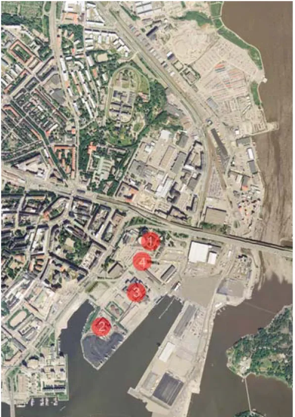
The indicated six regions are proposed sites with new urban development projects.
Figure 1 Map of Helsinki, Finland
1. Jatkasaari 2. Kruunuvuorenranta 3. Kalasatama 4. Arabianranta 5. Finlandiapark 6. Pasila 1
The area of Kalasatama has very important industrial history because Helsinki’s first large power station and gasworks were built there in the 1910s. This initial step produced a series of production buildings for engineering and subsequent power stations on the site of Kalasatama. Respectively, Helsinki’s major energy plants, the Hanasaari A and B power plants, were built in the 1950s and 1970s. Within Kalasatama, Hanasaari is marked as an energy supply area where these two power plants, the coal pile area, and the Suvilahti steam power stations are found. In the area between the northern side of the Hanasaari B power plant and the Suvilahti power station, a new station for technical supply and a future power plant are planned.2 The operation of the Hanasaari B power plant continues until 2025-2030, when a new power plant will be built. Coal and oil are the major energy sources to provide electricity in
Helsinki; however, gas and garbage disposal as well as other ways of generating electricity will be considered for the future power plant.
Figure 2 Hanasaari A (right) and B (left) power plants
Figure 3 Old gaswork in Suvilahti
2
Architectural Importance of the Suvilahti
In terms of the industrial history of Kalasatama, the early 1900’s buildings of the electricity plant and gasworks were the most advanced production plants at that time, and they were the first reinforced concrete structure made with new construction materials. Selim A. Lindqvist, a Finnish architect, was influenced by the Viennese architecture and designed the Suvilahti power plant buildings with his
impressions of that style. With its unique location in which all the traffic elements meet, both gasworks, a concrete form and an iron skeleton, were also landmarks in the area of Kalasatama. They achieved a unique combination of architectonics and functions. In addition, the power plant is the most important industrial work of architecture in Finland; therefore, its preservation and restoration must be conducted properly. This is one of the reasons why the old buildings of the Suvilahti power plant should be respected and preserved. The recommendation of new architectural interventions must be considered while the existing structures and facades are being preserved and maintained in order for people to keep the old image of the power plant. Because of the need for preservation and restoration of this power plant, the rehabilitation of the Suvilahti power plant is a very important matter for the Helsinki City Planning Department.
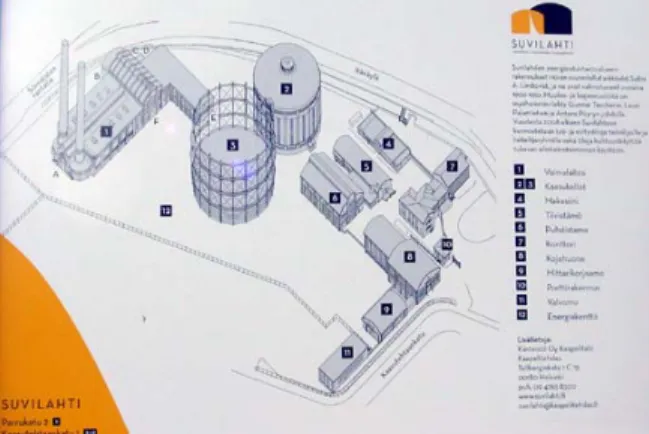
Figure 4 Suvilahti gasworks and warehouses
Figure 6 Map of Kalasatama: Suvilahti power plant (1), Hanasaari A power plant (2), Hanasaari B power plant (3), plot of future power plant (4)
Circulation within Site Context
A series of studies for circulation around the power plant was conducted. The examination of the present conditions of the existing site of Kalasatama determines that, first, there should be enough parking spaces to accommodate automobiles for visitors and workers. Then, for those who desire to use public transportation, metro, tram lines, and bus stations should be also available. For pedestrian access, people can walk through the two bridges, located across from the main street, Sornaisten Rantatie.
Parking
Park-and-ride parking will be available under Kulosaari Bridge and the metro station. The accommodation will provide parking spaces f approximately 1,800 cars. The spaces will be used at various time customers, workers, and residents in a range of 400 m distance. T short-term parking will be available for shoppers on the street side. The parking garage will be located above the ground level. The distance between the parking garage and buildings is 400 m. Alternative programs for different types of parking will have diffe hours: 5 pm - 8 am for residents and 8 am - 5 pm for workers. street parking will provide service for shoppers and visitors.
or s for he
rent
On-Public Transportation Terminal
The groun l form the public
3
Figure 7 Parking
d level under the existing metro station wil
transportation terminal. Trams will be provided from the north to the south along the streets and several stops will be located near the metro station at the gasworks. Under the metro station, there will be two bus arrival platforms, three bus parking spaces, and a 65-m departure platform.
Figure 8 Bus and Tram Lines
3
Sideways from the bridges and the metro station will be designed to provide access to a new museum in the Suvilahti area. The
waterfront area of Kalasatama provides a promenade for pedestrians and cyclists to future parks and shops. Future Kalasatama residents will walk along the edge of the waterfront and gain access to the Suvilahti area. There is an island which can be accessible via Kulosaari Bridge. The island is intended for a future recreational a There will be three different kinds of roads: main roads, feeder streets, and local streets. Local streets provide circulation among future residential and commercial buildings. A new road and street will be built adjacent to the new power plant. They will be used for people to ride a free shuttle to a new museum.
rea.
Circulation within the Suvilahti buildings
Figure 9 Roads and Streets
Some portions of the existing landscape in the Suvilahti area will remain to keep the old image of Helsinki’s first large power plant, so people still can picture the site even after new construction occurs. Within the site, where people were able to move around from one building to another through the existing structure, a new system of circulation will be applied and built to link all the buildings and to free open space in the landscape.
Design Problem: Adaptive Reuse of Suvilahti Structure
The Suvilahti steam power plant consisted of eight warehouses, two gasworks, and one power station. The uniqueness of their architecture is that it contains different sizes and heights, and different shapes of individual roofs. Buildings have different designs and colors of the facades and shapes of windows and doors. There are two gasworks: a concrete form and an iron skeleton structure. The other building with two chimneys is the power station with the main offices (see Figure 11). The challenge for this thesis was to create a museum that would celebrate the history of Suvilahti, the first large power station in Helsinki. The issue was how to create an architectural intervention which would integrate all the buildings as a whole in the site and have them communicate each other. Therefore, creating a mean of circulation for Suvilahti was the main issue for this project. The goals for this project were the protection of the buildings along with the preservation and the restoration of their facades and roofs.
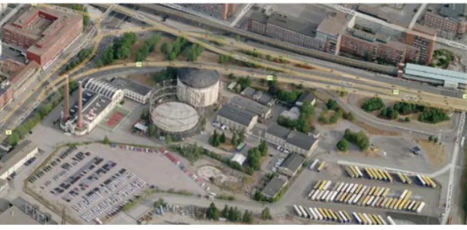
Figure 11 Bird's eye view of the Suvilahti power plant in Kalasatama, Helsinki
The design of a museum generally has a certain path of circulation that allows a visitor to experience each gallery with a different spatial form and light quality. The certain path has to be determined in order to achieve these characteristics. Once the different circulation paths for different users, are designed, then it is easy to identify different programmatic spaces in each building for these users. Functions are assigned to all the Suvilahti buildings with unique designs of spaces and light systems will be created according to the assigned functions.
Because there are a number of the buildings and warehouses in Suvilahti, the design for the two gasworks with functions and architectural spaces have to be different and distinct from the designs for the other eight buildings. The two gasworks have different structural systems made of concrete and iron. The designs of their façades and sizes are unique; therefore, each of the two has to be different as well in terms of spatial forms and functions.
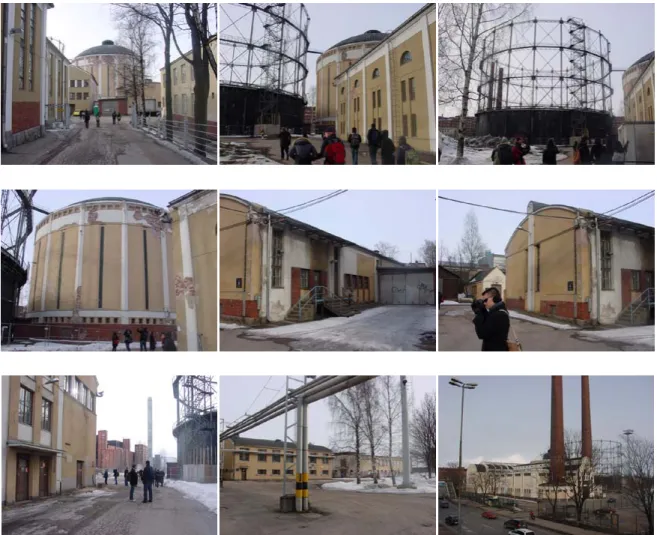
Figure 12 Site visit to Kalasatama in March, 2009
In terms of the method of constructions and the use of materials, there are certain restrictions that a builder has to consider. Because of the full protection of the roofs, heavy construction such as concrete and steel structures cannot be done; however, light construction such as timber structures and fabrication by small pieces can be preferable for a new intervention. The new interventions that happen outside of the warehouses and gasworks can be built with concrete and steel structures.
This thesis investigates different design approaches and options that will integrate all the buildings in Suvilahti. These studies can help to renovate the individual facility of the Suvilahti power plants with suitable features. The result of these investigations will also become guidelines for future projects such as the Suvilahti power plants, which need complete preservation but also the transformation of the spaces with new functions.
Precedents -- The study of precedents provides an initial step with which to begin a preliminary design of
the Suvilahti power plant.
Caixa
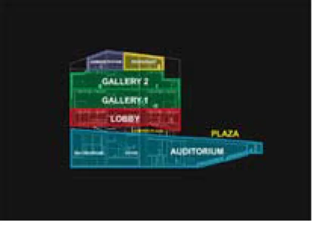
This project by Herzog & Meuron, a cultural center transformed from a power plant, has some potential interventions which can be applied to the Suvilahti power plants in Kalasatama, Helsinki. Caixa was the former Central Electricity station and also served as one of the important industrial buildings in the late nineteenth century in Madrid. The concept of this project was to retain the original façade of the existing factory. However, the walls on the lower portion of the first floor were removed to free the landscape and create a public plaza which opens all four sides of the building to the streets. In other words, the building seems to be lifted up one level. The plaza becomes the main access point where people can enter the building. In addition, new volume was added on the top of the existing structure of this old power plant as an expansion. With the interventions of new designs, not only does the building preserve the image of its old power plant but it also becomes a new landmark in Madrid. 4
Figure 13 Old Caixa before the transformation
Figure 14 Caixa in Madrid, Spain
4
Figure 15 Conceptual sketch
Figure 16 Placement of programs in spaces
Figure 17 Analysis of designs and programs
It was difficult to find projects relevant to my thesis. First, I wanted the façade and the structure to be completely preserved; however, my intervention in Suvilahti had to be monumental. Designs like Caixa influenced and improved my project. In the end, I was not sure how to tear down bricks and insert a gallery box onto the existing structure. In addition, this elimination would not achieve my goal of complete preservation.
Tate Modern
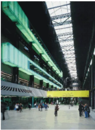
The Tate’s new interventions happen in the old building of a power station, with adaptations. As Rowan Moore states, “the exhibition galleries are designed to feel solid and room-like, rather than provisional arrangements of partitions…,”5 so instead of putting walls and partitions to create gallery spaces in the building, the architect created an individual volume with unique functions in each chamber of the galleries. In the Tate Modern, each of the galleries was designed to have different proportions and also different lighting systems. These galleries could have different heights of ceilings and sizes of windows, so a visitor could have uniquely different spatial experiences while watching physical artifacts exhibited in the rooms. In the competition of 150 entries, Herzog & de Meuron, from Basel in
Switzerland, won because their proposal design showed the fewest changes to the fabric of the power station and Bankside while other architects’ proposals “ma[de] strange complicated shapes or obliterat[ed] the past.”6 With few interventions on the fabric of the building, the juries from the competitions thought that Londoners would still recognize its actual image and the existence of the power station. The vertical chimney, the main icon of the power station, was not touched, but the turbine hall transformed into a public space for works of art. The street-level deck and the machinery from the turbine hall were removed and in each story, new structures were added to support the galleries.
Figure 18 Tate Modern in London, UK
5
Moore Rowan. pg 9. 6
Figure 19 Galleries plugged on the wall inside the Tate Modern
Figure 20 Cross-section of the Tate Modern
Figure 21 Longitude Section
Again, this project is done by the same architect, Herzog & de Meuron from Basel, Switzerland. The idea of the design is pretty much similar to Caixa in Madrid, Spain. Less than the entire façade and structure was preserved. My top priority in my thesis is to preserve the façade and structure as much as possible. The interventions in the Tate Modern are admirable, but if one wants to build something similar, it may prove very expensive.
Morgan Library
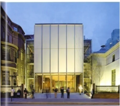
The Morgan Library is another great example, showing how the new intervention was inserted in the existing site while preserving the original façades and structures of the three historic buildings in New York. The library consists of the McKim building, the Annex, and the Morgan House in three corners of the block while the interventions are inside of the interstitial spaces among the three buildings. Renzo Piano, an Italian architect, wanted to free the three historic buildings by detaching them from other structures and additions that had been made and distracted from these prime landmarks. His new design interventions would be situated within the space circumscribed by the three buildings. Basically these insertions were made “between the McKim building and the Annex, between the Annex and the Morgan House, at the back of the Morgan House, and between the house and the apartment building next door on 37th Street.”7 These insertions linked three of these buildings, and the central courtyard was created in the middle of the three buildings and the insertions. The new buildings or insertions serve as offices, reading rooms, dining room, and auditorium. The center piazza became a major hub, connecting all these
insertions and the three historic buildings.8 Piano proposed that the adjacent buildings around the central courtyard would function like a village with historic rooms and galleries with collections. Other public areas like the shop and café would be located near the main entrance in the small pavilion on Madison Avenue between the McKim building and the Annex. Without eliminating or demolishing anything, Piano successfully achieved his goal of designing a new library by just connecting the three historic buildings.
Figure 22 A model of the Renzo Piano proposal
7
Byard, Paul Spencer. pg 47. 8
Figure 23 Original view of the Morgan Library
Figure 24 Model of New Morgan Library
Figure 25 Front view of the Morgan Library in New York, NY
I visited the Morgan Library with my HTC preservation class at MIT in spring, 2009. I was overwhelmed by how Renzo Piano placed his new buildings among the three historic buildings in New York. While visiting, I did not find much demolition of either the façade or the structure. The project cost was high because the builder had to dig to build an underground auditorium under the library. However, using the concept of these simple insertions helped to refine my design.
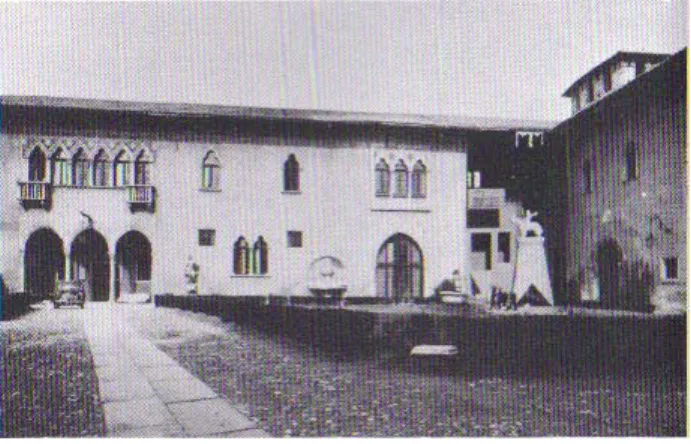
Castelvecchio
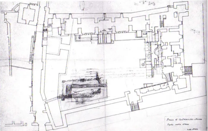
In Verona, Italy, Castelvecchio is an old military fortress, converted into a museum by an Italian architect, Carlo Scarpa. In the design, he introduced small pieces of construction and attached them to the old buildings. Basically the new interventions of his architectural elements interweave with the fragments of old buildings and their history. He left the façades of the buildings partially uncovered and tried to rediscover the past by exhibiting some of his new designs along with old artifacts on the façade and in the space. He created a new narrative and designed a new landscape.9 Castelvecchio is the example in the analysis of the precedents showing the fewest changes while producing a new intervention in the old castle. His design extended to details of doorways, staircases, furnishings, and fixtures of the previously empty space. All of this craftsmanship was put together and transformed the fortress into new gallery spaces.
Figure 26 Drawing of Castelvecchio, Verona in Italy
9
Figure 27 Original facade before the transformation into a museum
Figure 28 Inside of a gallery space in Castelvecchio
Figure 29 Inside of a museum
I visited Castelvecchio in spring 2000 while spending a semester in an overseas program. I did not understand Carlo Scarpa’s design at that time, but when I studied it for my thesis, instead of ripping walls apart, introducing small constructions such as jewel-like boxes of galleries and platforms for exhibitions was a unique and better approach. This major work of architecture emphasized detailing his small constructions and attaching them to the skin of the building. I think that Carlo Scarpa successfully preserved the façade and structure of the existing building.
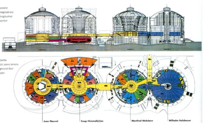
Gasworks in Vienna, Austria
The multi-use approach was involved in the four gasworks in Vienna, Austria. Because they are a city’s monuments and landmarks, the external façades of the four gasworks were preserved. With the buildings’ small windows, the roofs had to be demolished and one large skylight was created in order to bring in natural light. Four different architects were assigned, one to each of the four gasworks’ designs. Variations of the design included a large indoor plaza, garden, and terraced structure around a cylindrical volume with multiple floors. The volumes were divided and sectioned into different functional spaces. The center of the new building was occupied by a lift and stairs. Overall, three designs included a tube-like cylindrical form, providing an open plaza with natural light. The spaces of the others were
centralized and their perimeters were used for individual gardens partitioned in sections.10
Figure 30 Site of gasworks in Vienna, Austria
Figure 31 Gasworks in Vienna, Austria
10
Figure 32 Gasworks after the renovation
Figure 33 Floor plans and sections of the gasworks
I think this project is the most remarkable in its renovation and the preservation. The ways the four architects designed spaces inside the gasworks were inspiring except for having their roofs demolished to allow skylights. In Suvilahti, the designs of the roofs are so unique that I decided to preserve all of them. I decided to build something inside the gasworks like these in Vienna. In Suvilahti, with the roof covered, timber structure was preferable for the construction.
Design Solution
Design Analysis of the Suvilahti: Connections
For the full protection of the existing structures, façades, and roofs of the warehouses and gasworks, small interventions were designed to connect buildings to combine the entire group of buildings as a whole. In addition, because of the constructability issues and the financing for the
renovation, making connections for each building was the best option in deciding the most feasible design. The goal of this project was not only to connect buildings, but also to free the flow of visitors in any directions.
Figure 34 Connections between buildings in multiple directions
Figure 35 Flow of movements to various directions
In any direction, a different transfer has to be achieved to move from one floor level to either lower or upper floors and from one space of the building to another space of another building.
spots of the space.
Figure 37 Possibilities of various views in different directions
Various forms and structures of infiltration can be made to create different spatial experiences in galleries.
Figure 38 Walls and cantilevered platforms in different structures
Various ways of invasions can be achieved depending on the placements of wall partitions.
Figure 39 Possibilities of various invasions in different ways
In terms of materials, some were clear glass for a visitor to see through, but others were opaque or solid walls to secure the space.
After the analysis of th ed for each case. A group of simp
according to Edward T by groups of their attrib
ate: An interstitial space is created between two blocks and metaphorically, the e different scenarios, different possible interventions were creat
le diagrams was produced for specific conditions for buildings and the site
. White’s Path Portal Place (see Figures 40-60). The diagrams are categorized here utes.11
Figure 42 Figure 41 Figure 40
G
space becomes a doorway between two walls.
Wall: When the layout of the building blocks is aligned but the gap is created between any of those elements, a new building block can be introduced to form a continuous wall in the interstitial space.
Zipper: Multiple “teeth” project from a single block on each side and their edges are joined and interlocked by a new element.
Bridge: A new structure spans and provides a passage between two blocks.
Figure 43
11
Knuckle: This system is like a zipper, but it can interlock many edges of the blocks angle around the central piece.
Consolidator: This shape is a more advanced form of a knuckle, a way of
I s shaded sha
consolidator. A new c ng
Dialog participant: Th
Feature building: This the void are at any
Figure 44
interlocking the building blocks in a dynamic way.
Figure 45
nfill: Thi pe is a far more advanced system than the knuckle and onstruction is built up in void areas where the buildi blocks are scattered.
Figure 46
is elevation is a cross-section of the conditions inside the wall, zipper, bridge, knuckle, consolidator, and infill.
Figure 47
form is like the system of dialog participant, but the shape a has a strange and complicated form to bring a focus from all other buildings and to the feature.
inserted in
Transition: It is like the two previous elements but in this case, the heights of the two blocks are relatively different, so the slope of a roof of a new block is angled to relate two top corners of the two blocks.
xpression of contextual regulating lines: This is like a consolidator; however, the width of the edge of a block which touches a consolidator is same as that of a
nes: A new block is created without referencing the site
Marriage: It is another version of a consolidator; its edges match the width of its elements.
Corner: This is a wall shape, but the alignment of the blocks is angled.
Figure 49 E consolidator. Figure 50 Violator of regulating li context. Figure 52 Figure 51 Figure 53
Figure 56 Figure 55 Figure 54 Figure 53
Boundary: The introduction of a new wall into existing adjacent walls creates an existing boundary condition or a central courtyard.
New face: An L-shape block is introduced on the corner of a courtyard or a large building block to reinforce certain facades or edges.
New interior in an old shell: A new intervention is created inside an old structure.
Edge reinforcer: It is like a new face but the form features an area by becoming irregular and complex, sometimes curving.
Space maker: This is the combination of the two conditions of a boundary and a new face.
Figure 58
Plaza: A plaza can create an underground space such as that at the Louvre in Paris.
Umbrella: A new structure is introduced in the air above the existing buildings on the ground.
terms of how and when people move around and get to the programmatic spaces. Using the provided diagrams, four new design techniques were used to model each case of the connections and the other interventions in order to determine what elements are the most suitable for this project.
Addition: This shape occurs when a new volume or structure is introduced in the existing site.
Subtraction: This design occurs when a part of existing spaces or facades is demolished and eliminated.
Multiplication: This design is the combination of addition and subtraction. The façades of the two blocks are eliminated and a new block is created and bridged between them.
Division: This design occurs when a building is cut by one piece. A new block is inserted to separate a building into two pieces.
Furthermore, four different new ways of controlling the spaces were applied to refine the details of the intervention design.
To invade: The space on the upper level of an existing building is possessed by a new element.
To infiltrate: An elevated block is created and suspended to make an enclosed space like a shelter. In another word, it is a space with a roof, but no walls.
To view: A new block is introduced on the top of an existing structure but by using the idea of umbrella and central support, an interstitial space from a new block and an old block is created to allow views and air through them.
To transfer: This design is like a bridge between two elements; however, this form sits on the top of the two existing structures instead of inserting into them.
All of the cases were considered to provide the most feasible structure and design for the Suvilahti power station.
These four elements were selected for the possible design: bridge, infill, knuckle, and zipper.
Figure 60 Bridge, infill, knuckle, and zipper (clockwise from the left)
The diagrams below are a series of different studies of the connections, applied according to White’s rules.
The bridge is basically a direct connection between two buildings, but it allows a visitor to go in only one direction.
Another kind of connection is created for a different circulation system.
Using the rule of “expression of contextual
regulating lines,” details of the edges of each of the bridges are modified.
However, a knuckle allows a visitor to move in multiple directions because it connects with multiple buildings nearby.
circulation system for every void among buildings.
some of the open spaces created by this zipper that provide a series of outdoor courtyards where future exhibitions can be displa
such as the gallery, café, bookshop, and auditorium. The private spaces, such as offices, will be treated as a
made after summarizing every details of the mini-diagrams’ attributes. Basically, this fina
cted
The goal is to allow people to move around without any restrictions. The system that solves this case is to infill. The idea of the infill is substituting the
On the other hand, a zipper is the best option,
containing all the elements of the first three because it combines not only all the bridges like a hub but also
yed.
After the study of a series of mini-diagrams and analysis of the precedents, the solution for the project of the Suvilahti was to establish the connections between the buildings and to assign different functions to each building. The facades of the original buildings will be retained for building preservation; therefore, the new interventions are the connections and the spaces inside the buildings. The connections are carefully inserted between certain buildings to create a promenade for a visitor to public spaces
separate element from the public spaces; therefore, offices will not be linked and will have their own entrances to the space.
The final proposal is
l version is like a zipper but it has been simplified to a bridge. A bridge is connected between buildings and a larger bridge is conne among bridges.
buildings were not laid out in order but were scattered and turned with different orientations. In other words, the biggest challenge for this project was to come up with a rational, practical circulating system which will guide various kinds of people’s movements and activities. In the structure of the site plan, the layout of the buildings looks organized but actually a lot of them were inconsistently oriented, offset from the grid structure of the site, and not aligned with the other adjacent buildings.
This inconsistent orientation means that when the connection is made between two buildings, it actually needs to be shifted at an angle to match the entrance from one building to that of the other building. In technical terms, a bridge is created between two buildings for the connection; however, a hub needs to be created to tie some of these bridges together to provide more opportunities to visitors to decide in which direction they want to go and see the exhibition. Eventually, several different sizes of connections were created and attached to the buildings. The transitional hub (a modified zipper) became a major backbone for tying all these connections together. Basically these hubs, created in certain spaces (see Figure 42), are like a central pavilion which provides choices for a visitor to transit to different areas. In other words, these hubs have connections like ribs (see Figure 42), connecting to the adjacent buildings. The widths and heights of the spine are relatively large because they represent a major transitional space for connecting all the buildings in between. In addition, they should be monumental so the selection of materials was also slightly different from that of the other connections (see Figure 43).
ed lso have similar features. Somehow all the interventions need to be related to the site context so averaging the heights and window lines of the two adjacent building façades determines the height of the connections and hubs are determined. The material of the connectors is glass because it emphasizes that each of the warehouses is different and the new interventions are independent of each other (see figure 43).
Figure 62 Connections and hubs between buildings
In terms of sizes, the widths and heights of these connections are determined by the actual dimensions of existing entrances. For example, if there are two doors on the building, then the width of the connection is measured from the point on the left to the point on the second door on the right end (see Figure 43). Their heights are differentiated and varied according to the heights of the buildings that they connect to. Like each warehouse, having different sizes and heights of the spaces and roofs, the attach cells could a
Figure 63 Sizes of connections and hubs in relation to the buildings
On the other hand, the placement and the arrangement of the connections were not randomly made, but their specific locations were selected to create an outdoor courtyard (see Figure 44). This outdoor courtyard can be accessed easily from the hub. These outdoor areas will be open in warm
seasons for future exhibitions. These places are nearly ideal for large physical artifacts such as machinery from the power stations, as well as experimental models and installations from the old and future energy productions.
Figure 64 Outdoor courtyards in between buildings and connections
The new interventions of connecting buildings not only provide access to move from one building to another but also facilitate other services like interactive media with internet access and digital
projections to guide and help visitors to understand the contents of galleries before they actually enter the room. A guided tour for group members will be available, but computerized systems will also provide a real-time service and communication with unlimited access to information.
Figure 65 Northwest view of the model
Figure 66 View from the south
Jewel-like boxes in each of the warehouses were created in the model for holding private collections. The rest of the other simulated spaces are open for general exhibitions (see Figures 48-49). Suspended cantilevered spaces were created to feature certain artifacts (see Figure 50). The 1-meter deep underground excavation was made to show the original foundation of the warehouses and the power plants (see Figure 51). In the inside of the warehouse, glass partitioned walls were created to shelter specific exhibitions, but they can be accessed and viewed only from the outdoor courtyard (see Figure 52). These glass chambers give some glimpses of what is being displayed, but in order to have clear views of the exhibits, a person has to go outside the building to the courtyard to see the particular exhibitions in the glass chamber. A number of the warehouses can be transformed for different functions by the
determination of the frequency of their use and their importance. Some examples are the café and bookstore because the buildings are located adjacent to the main entrance. The auditorium also needs to be located nearby in order for an educator or other to try to quickly get to them. Then a series of different galley spaces is followed by the cafe and bookstore.
Figure 68 Jewel-like boxes for private collections
Figure 70 Suspended cantilevered spaces
Figure 71 Underground excavation
Based on the study of the four gasworks in Vienna, Austria, new volumes and structures are inserted in the void of the two gasworks in Kalasatama. Each of these new volumes represents an old image of a gas tank. It is a cylindrical form with a curved dome on the top. Based on the Austrian concept, the form is sectioned by several cuts and these cuts become partitions between the sections of the spaces generated in the cylindrical block (see Figure 53). The partitions are used for vertical circulation for stairs and elevators. The other generated spaces are for gallery spaces. The material of the wall in the partition is glass to allow natural light from the outside. They are also a lobby and restrooms. There are seven floors in the iron skeleton structure gaswork (see Figure 54).
Figure 73 Gas tank partitioned by cuts
Figure 74 Seven floors in an iron skeleton gaswork
In contrast, the intervention in the concrete structure is similar to that of an iron skeleton structure. The only difference between the iron skeleton and the concrete structure is that the concrete one has an indoor gallery combined with the circulation around the circumferences of the gasworks. It does have an opening in the center to allow skylight from the roof. The private chambers are created around this opening to accommodate special collections for exhibitions. The two gasworks are connected by a bridge
from the top floor of the concrete building to the fourth floor on the iron skeleton gaswork because people do not need to come out from one gaswork in order to transfer to the other gaswork.
Figure 75 Indoor galleries with circulation
Figure 76 First floor of a concrete structure gaswork
Figure 77 Section of the two gasworks
In terms of the constructability issues, the roof of a concrete structure has to be preserved; therefore, timber structure or small construction by assembling small pieces in joints is allowed for this
Concrete construction for this gaswork is desirable for building the main structural frames.
Figure 78 Concept model for an iron skeleton gaswork
Figure 80 First floor of the gas tank in a concrete gaswork
Figure 81 Open-plaza inside the gas tank in an iron skeleton gaswork
Exhibition Narrative
The circulating spaces will be sequenced by the history and development of energy. Some possible questions can be raised, such as how energy is created from ancient time, to the present, to the future. Society talks out about how energy use started and how it changes from man- and animal-powered energy to machine-animal-powered. The issues are massive production, industrialization, and lack of limited resources such as fossil fuels (gas, oil, coal). We also talk about what caused the transformation of energy use from fossil fuels to renewable energy. The museum not only exhibits examples of
machines of energy production from ancient time to present-day power plants to solar power panel and turbines, but it also generates the story of why these changes were made. For example, global warming and air pollution are big issues. Distributing massive production and large demand are other issues. Basically, the reconstruction of the circulation path narrates the story, telling alternative ways to find different energy sources in chronological order.
Amenities
1. Information desk, coat & luggage checks, first aid office, audio guides, telephone 2. Gallery (ancient technology, present-history of Kalasatama, future of power plant) 3. Café, restaurant, restroom
4. Bookshop, gift shop, library 5. Office for research and education 6. Auditorium
Details of Contents in the Gallery Spaces
• Facts and information about technology in gasworks • Kalasatama and its power plants (gas, oil, and coal) • History of gasometers and the gasworks
• Architecture of gasometers and photogallery with pictures of gasworks from today and the past • Exhibitions for physical artifacts, models, and drawings
• Digital gallery with projections, interactive media, and real-time experimental scale models
Contents of Gallery in the Warehouses
• Exhibitions for ancient technology
• Examples from Greek, Egyptian, and Chinese technologies, man-made energy by machines, use of nature such as gravity, water flow, and wind
• Collection of present-day power plants (coal, old, gas) • History of Kalasatama and its energy use
• History of gasometers and the gasworks • Architecture of gasometers
• Showroom of the entire Kalasatama area
Contents of Gallery in Concrete Structure Gaswork
• Automation, future of new power plants, possibility of new intervention in power plant design • Examples of new energy: use of microscopic green algae; hydrogen economy--abundant,
inexpensive, nonpolluting; garbage disposal; nuclear energy; carbon sequestration plants; carbon dioxide power plants
• Design of a future power plant that will turn coal into a hydrogen gas rather than burning it directly, split water into hydrogen and oxygen under controlled conditions
• New technology with cutting edges, digital power plant of the future in Kalasatama
Contents in the Connections
There will be interactive media telling stories about how man-powered energy, fossil fuels and renewable energy have been transformed. The transitions are global warming and impacts on the environment, the increase of the human population, high demand, limited natural resources, industrialization and the machine age, the air and water pollution.
Figure 84 Floor Plan (1st Floor Level)
Programs in Suvilahti power plant buildings 1. Lobby 2. Gift shop 3. Restaurant 4. Reception 5. Auditorium 6. Office 7. Gallery
Conclusion
Because of the lack of information on drawings and history of the Suvilahti power plants, it was difficult to produce a design of the power plants. Technical data such as dimensions and distances of the site were approximated by looking at the satellite images on the Internet. Because Finland’s Energy Department is so protective of their plans and history, most of the design was created from a one-time site visit and illustrations created after the site visit. If correct data had been provided, more accurate research could possibly have been performed, and the results for this project would have been more precise.
If there had been more time for this project, designing the detail of the connections and gasworks would have been more fully achieved. Moreover, accurate placing of structural columns for the
connections also could have been done from studying the grid structure of the Suvilahti site. With drawings of the floor plans of each warehouse, more careful observation for the inside of the buildings could have been made in order to produce more intricate design of the interior of the buildings.
In the future, the study of mini-diagrams of different interventions from this project can be another strategy for an architect who wishes to pursue future restoration of a project like the Suvilahti power plant.
“I can do everything through him who gives me strength.” (Philippians 4:13)
I thank you God for my many blessings and you have stayed with me even until the last moment I finished this thesis work.
I thank my professor, Kent Larson, who has endlessly supported me to finish my thesis. I never forget his big smile, which has made me motivated all the time even though I had many difficulties throughout the spring semester and the summer of 2009.
I thank my parents, who have supported me to study abroad in the United States for the last sixteen years. I thank my older sister, who has prayed and prayed endlessly.
I thank M.I.T., giving me the time to have the greatest turning point in my entire life. Thank you. Amen.
Bibliography
Beltramini, Guido. Carlo Scarpa. Milano; Electa; 2000.
Blazwick, Iwona. TATE MODERN the handbook. Los Angeles: University of California; 2000.
Byard, Paul Spencer. The Making of the Morgan from Charles McKim to Renzo Piano. New York: The Morgan Library & Museum, 2008.
Carlo Scarpa, Architect: Intervening with History.
<http://www.absolutearts.com/artsnews/1999/08/06/25764.html>
Competition entry: evaluation report:
<http://www.hel.fi/static/ksv/www/Projektialueet/Kalasatama/kalasatama_nettiversio.pdf>
Gasometer City, Vienna, Austria.
<http://www.cse.polyu.edu.hk/~cecspoon/lwbt/Case_Studies/Gasometer_City/Gasometer_City.htm>
Helsinki Competition Brief.19 July 2009
<http://www.hel.fi/static/ksv/www/Projektialueet/Kalasatama/Helsinki_Eastern_Harbour_Competition_lo res_291004.pdf >
Moore, Rowan. Building Tate Modern: Herzog & De Meuron Transforming Giles Gilbert Scott. London: Tate Gallery Publishing, 2000.
Murphy, Richard. Carlo Scarpa & Castelvecchio. Venezia: Arsenale Editrice, 1991. Newhouse, Victoria. Towards a New Museum. New York: The Monacelli Press, 1998.
Responsive City. <http://wiki.uiah.fi/futurehome/doku.php?id=responsive_city>
White, Edward T. Path, Portal, Place: Appreciating Public Space in Urban Environments.Tallahassee: Architectural Media Ltd, 1999.
p.6, fig. 1: Dynamic Helsinki: New Urban Development Projects.
<http://www.hel2.fi/taske/Dynamic_Helsinki/Helsinki_MIPIM_2009.pdf>
p.7, fig. 2: Hanasaari. 19 July 2009. <http://www.flickr.com/photos/timonoko/2264980624/> p.7, fig. 3: Helsinki Competition Brief.19 July 2009.
<http://www.hel.fi/static/ksv/www/Projektialueet/Kalasatama/Helsinki_Eastern_Harbour_Competition_lo res_291004.pdf >
p.8, fig. 4, fig. 5: Suvilahti; 19 July 2009. < http://www.suvilahti.fi/galleria/> p.10, fig. 7, fig. 8: Helsinki Competition Brief.19 July 2009.
<http://www.hel.fi/static/ksv/www/Projektialueet/Kalasatama/Helsinki_Eastern_Harbour_Competition_lo res_291004.pdf > 32.
p.11, fig. 9: Helsinki Competition Brief.19 July 2009.
<http://www.hel.fi/static/ksv/www/Projektialueet/Kalasatama/Helsinki_Eastern_Harbour_Competition_lo res_291004.pdf> 32.
p.11, fig. 10: Park, Sung-o. Map of Suvilahti. March 2009.
p.12, fig. 11: Bing Maps, 21 July 2009. <http://www.bing.com/maps> p.13, fig. 12: Park, Sung-o. Site Visit to Kalasatama. March 2009. p.14, fig. 13: ©Herzog & de Meuron.
<http://www.arcspace.com/architects/herzog_meuron/caixa/caixa.html> p.14, fig. 14: ©Christian Richters.
<http://www.arcspace.com/architects/herzog_meuron/caixa/caixa.html> p.15, fig. 15-17: ©Herzog & de Meuron.
<http://www.arcspace.com/architects/herzog_meuron/caixa/caixa.html> p.16, fig. 18: <http://z.about.com/d/architecture/1/0/I/t/TateModernFlickr.jpg>
p.17, fig. 19: < http://www.architecture.com/Images/RIBATrust/Awards/RoyalGoldMedal/2007/Tate-Modern-interior_530x722.gif>
p.17, fig. 20-21: Moore, Rowan. Building Tate Modern: Herzog & De Meuron Transforming Giles
Gilbert Scott. London: Tate Gallery Publishing, 2000, 174- 175.
p.18, fig. 22: Byard, Paul Spencer. The Making of the Morgan from Charles McKim to Renzo Piano. New York: The Morgan Library & Museum, 2008, 45.
p.19: fig. 23-24 Andrew Cusack. 19 July 2009. <http://www.andrewcusack.com/2007/09/10/the-architects-they-really-hzate-us/>
p.19, fig. 25: Byard, Paul Spencer. The Making of the Morgan from Charles McKim to Renzo Piano. New York: The Morgan Library & Museum, 2008, 77.
p.20, fig. 26: Murphy, Richard. Carlo Scarpa & Castelvecchio. Venezia: Arsenale Editrice, 1991, 22. p.21, fig. 27, Murphy, Richard. Carlo Scarpa & Castelvecchio. Venezia: Arsenale Editrice, 1991, 26 p.21, fig. 28: Murphy, Richard. Carlo Scarpa & Castelvecchio. Venezia: Arsenale Editrice, 1991, 68. p.21, fig. 29: Castelvecchio Museum. 21 July 2009.
<http://www.comune.verona.it/Castelvecchio/cvsito/english/collez1.htm > p.22, fig. 30-31: Gasometer Complex. 21 July 2009.
<http://www.skyscrapercity.com/showthread.php?p=23663586> p.23, fig. 32- 33: Gasometer Complex. 21 July 2009.
<http://www.skyscrapercity.com/showthread.php?p=23663586>
p.26, fig. 40-43: White, Edward T., Path Portal Place: Appreciating Public Space in Urban
Environments. Tallahassee: Architectural Media Ltd; 1999; 18-21.
p.27, fig. 44-48: White, Edward T., Path Portal Place: Appreciating Public Space in Urban
Environments. Tallahassee: Architectural Media Ltd; 1999; 18-21.
p.28, fig. 49-53: White, Edward T., Path Portal Place: Appreciating Public Space in Urban
Environments. Tallahassee: Architectural Media Ltd; 1999; 18-21.
p.29, fig. 54-58: White, Edward T., Path Portal Place: Appreciating Public Space in Urban
Environments. Tallahassee: Architectural Media Ltd; 1999; 18-21.
p.29, fig. 59-60: White, Edward T., Path Portal Place: Appreciating Public Space in Urban