Blade-Mounted Actuation for Helicopter
Rotor Control
by
Matthew Edward Fox
S.B. Massachusetts Institute of Technology (1990)Submitted to the Department of Aeronautics and Astronautics in partial fulfillment of the requirements
for the degree of
Master of Science
at the
Massachusetts Institute of Technology
June, 1993@
Massachusetts Institute of Technology 1993. All rights reserved.A L
Department of Aeronautics and Astrona itics February 26, 1993
Certified by
-Professor Steven R. Hall Department of Aeronautics and Astronautics Thesis Supervisor Accepted by
Aero
MASSACHUSETTS INSTITUTE OF TF rLOinl n19y"JUN 08
1993
L1h ,mtz II -,(rofessor Harold Y. Wachman Chairman, Department Graduate Committee
%IJI r
,
Blade-Mounted Actuation for Helicopter Rotor Control
by
Matthew Edward Fox
Submitted to the Department of Aeronautics and Astronautics on February 26, 1993, in partial fulfillment of the
requirements for the degree of Master of Science
Abstract
The feasibility of using blade-mounted actuators for helicopter rotor control is inves-tigated. A state space model of a helicopter rotor is developed by making several simplifying assumptions that yield time-invariant dynamics. This is convenient for control design, because transfer functions from control inputs to hub loads may be obtained. The transfer functions allow conventional and blade-mounted actuation methods to be compared for steady and multicyclic inputs. Furthermore, the model relates blade lift and pitch to control inputs by general aerodynamic coefficients, so that any blade-mounted actuator may be incorporated into the model.
The rotor model is semi-articulated with rigid blade flapping, but it is derived so that flapwise bending can be included, if desired. The model incorporates elastic blade torsion as well as rigid blade pitch, so that both controllable twist and full blade feathering can be investigated. Simple linear aerodynamics are assumed with a dynamic inflow model that can be used for both hover and forward flight.
Piezoelectric servoflap actuation is investigated for the H-34 research rotor, with emphasis on higher harmonic vibration control. The servoflap is capable of suppress-ing higher harmonic vibrations, and can be used to augment full blade feathersuppress-ing for collective and cyclic control. The servoflap is able to provide 0.25 g of higher harmonic vibration control with deflections on the order of ±5 deg. Piezoelectric actuation is potentially feasible within this range.
Acknowledgments
This research was funded by Boeing Helicopters under Contract Nos. ABQ024 and ACP853, with Mr. Jim Keller serving as technical monitor. We appreciate the as-sistance of Mr. Keller who provided the wind tunnel data used in this research, and Mr. Rich Teal, also of Boeing Helicopters, who provided technical consultation. We would also like to thank Mr. Frank Tarzanin and Ms. Joyce Peranteau of Boeing Heli-copters for supporting the C-60 program used in this research. Finally, we would like to thank Mr. James Garcia of M.I.T. for providing the C-60 data that is presented in this report.
Contents
1 Introduction
1.1 Helicopter Rotor Control . . . . 1.2 Rotor Control Methods . . . . 1.3 Higher Harmonic Rotor Control . . . . 1.3.1 Sources of Higher Harmonic Vibration . . . . . 1.3.2 Helicopter Vibration Requirements . . . . 1.3.3 Overview of Vibration Suppression Technology . 1.3.4 Higher Harmonic Control Algorithms . . . . 1.4 Thesis Overview ...
2 Rotor Vibration Spectrum from Wind Tunnel Data 2.1 HHC Disturbance Rejection Theory . . . . 2.2 W ind Tunnel Tests ...
2.3 Data Reduction ... 2.4 Data Analysis ...
3 Blade-Mounted Piezoelectric Actuation 3.1 Strain Actuation Materials ... 3.2 Piezoelectric Theory ...
3.3 Piezoelectric Actuation of Rotor Blade Twist . . . . 3.4 Piezoelectric Servoflap ...
4 State Space Rotor Model Derivation 4.1 M ultiblade Coordinates ... 17 S . . . . . 18 S . . . . . 20 S . . . . . 21 . . . . . 21 . . . . . 22 S . . . . . 25 S . . . . . 36 . . . . 44
4.2 Rotor Model Characteristics ... 90
4.3 Blade Torsional Modal Analysis ... .. 93
4.4 In Vacuo Blade Dynamics ... 96
4.5 Aerodynamics ... ... . 104
4.6 Hub Reactions . .. .. .. ... .. .. .... ... .. 111
4.7 Inflow Dynamics ... 117
4.8 State Space M odel ... 119
5 State Space Rotor Model Results 127 5.1 C-60 Aeroelastic Rotor Analysis Program . ... 127
5.2 Validation of the State Space Rotor Model . ... 128
5.3 Results for the H-34 Research Rotor . ... 133
6 Conclusions 151 6.1 Review of the State Space Model Results . ... 151
6.2 Recommendations for Future Research . ... 153
A Rotor Blade Integrals 155
B Matrices for Rotor Dynamics 157
List of Figures
1-1 Human factor vibration requirements. . ... 24
1-2 Transmission of harmonics. . ... . . . . . 37
1-3 Block diagram of the discrete-time HHC algorithm. . ... . 39
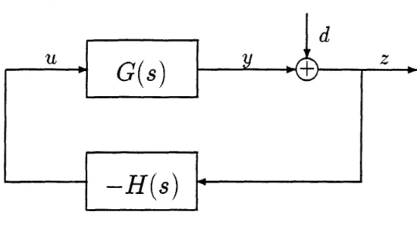
2-1 Block diagram of closed-loop compensation. . ... . . . . . 49
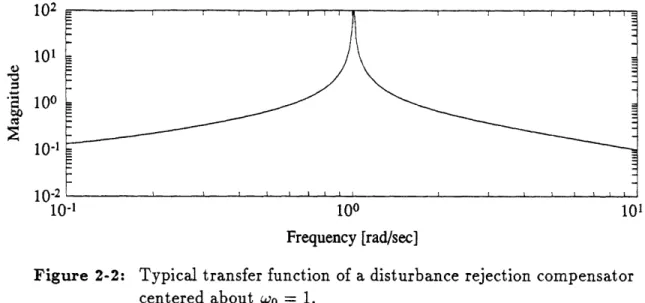
2-2 Typical transfer function of a disturbance rejection compensator.... 50
2-3 Block diagram of the continuous-time HHC algorithm. ... 51
2-4 Transfer function of a typical HHC compensator H(jw)... . 54
2-5 Sensitivity transfer function of a typical HHC compensator S(jw). .. 54
2-6 Open-loop and closed-loop power spectral densities for a typical HHC compensator in response to a random disturbance. . ... . . 54
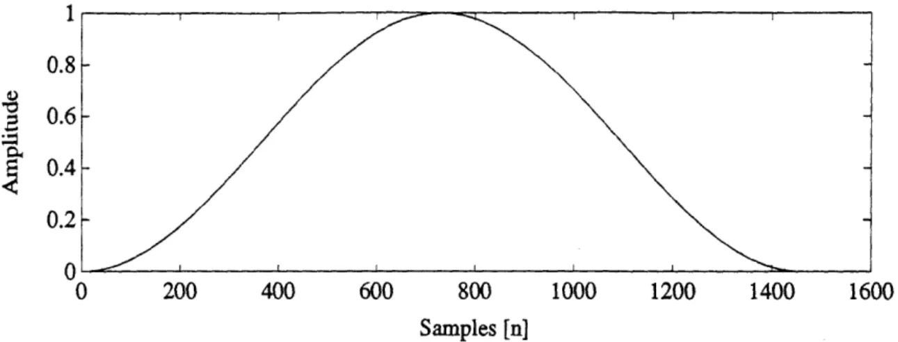
2-7 Hanning window. ... ... ... . . 57
2-8 Discrete frequency transform of the Hanning window ... . 58
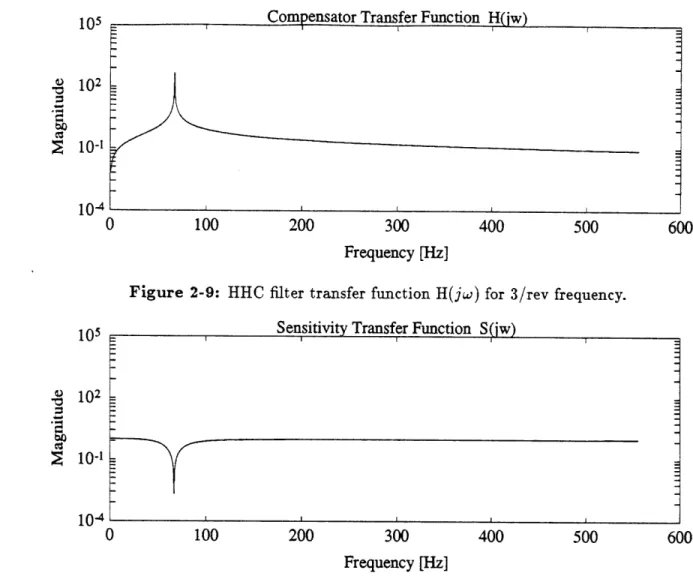
2-9 HHC filter transfer function H(jw) for 3/rev frequency. ... . 60
2-10 HHC filter sensitivity transfer function S(jw) for 3/rev frequency. .. 60
2-11 Vertical hub force time history for Run 164.01. ... ... 62
2-12 Vertical hub force power spectrum for Run 164.01... . . . 62
2-13 Open-loop vs. closed-loop power spectrum for Run 164.01. ... . 62
2-14 Vertical hub force time history for Run 175.04. ... . ... 63
2-15 Vertical hub force power spectrum for Run 175.04 ... 63
2-16 Open-loop vs. closed-loop power spectrum for Run 175.04. ... . 63
2-17 Vertical hub force time history for Run 179.03. ... . 64
2-19 Open-loop vs. closed-loop power spectrum for Run 179.03.
3-1 Longitudinal/transverse piezoelectric operation .... . . . .... . . 71
3-2 Shear piezoelectric operation . . . . ... . . 72
3-3 Piezoelectric bender wired for series operation . ... 73
3-4 Piezoelectric bender wired for parallel operation . . . . 74
3-5 Partial attachment of a DAP ... ... .. 76
3-6 Transverse shear lag of a DAP .. . . . .. . . . . . 76
3-7 DAP beam actuated for twist. . ... . .. 77
3-8 DAP rotor blade section. . ... .... ... . 78
3-9 Cross section of piezoelectric servoflap mechanism . . . . . . 79
4-1 Rotor blade azimuth angle ?k, and blade indices. ... . . 86
4-2 Rotor blade geometry (side view). ... . . . .. . . . 91
4-3 Orgin of the propeller moment. ... 102
4-4 Aerodynamics of the rotor blade ... . .. . .. . . . 105
4-5 Rotor disk coordinates and direction of hub loads. . ... . . 111
4-6 Hub moment due to vertical shear force and hinge moment . . . . . 115
5-1 Effect of inflow dynamics on thrust response due to collective pitch, for the H-34 rotor in edgewise forward flight for several advance ratios. 137 5-2 The effect of blade torsional stiffness on the thrust response of the hovering H-34 rotor due to collective pitch actuation . . . . . 142
5-3 The effect of blade torsional stiffness on the thrust response of the hovering H-34 rotor due to collective servoflap actuation .. . . . 143
5-4 The effect of advance ratio on thrust response due to collective pitch actuation for the H-34 rotor in edgewise forward flight . . . . . . 147
5-5 The effect of advance ratio on thrust response due to collective servoflap actuation for the H-34 rotor in edgewise forward flight . . . . . 148
List of Tables
2.1 Parameters for HHC wind tunnel test. . ... 56 2.2 Vibration reduction results. ... 61
4.1 State space equation for the dynamics of the rotor disk modes. .... 122 4.2 State space equation for the hub loads. . ... 123 5.1 Parameter comparison of the state space model and C-60 program for
the generic rotor. ... 130 5.2 Comparison of blade twist and rotor thrust for the state space model
and C-60 program for the generic rotor (elastic torsion only). ... 132 5.3 Comparison of flapping angle and rotor thrust for the state space model
and C-60 program for the generic rotor (flapping motion only)... 132 5.4 Parameter comparison of the continuous and discrete mass models for
the baseline H-34 rotor ... 134 5.5 Flapping angle, tip pitch, blade loading, and thrust responses for the
baseline H-34 rotor with torsionally stiff blades (71 = 7.65). ... 139 5.6 Flapping angle, tip pitch, blade loading, and thrust responses for the
baseline H-34 rotor with moderately stiff blades (71 = 4.50). ... 139 5.7 Flapping angle, tip pitch, blade loading, and thrust responses for the
baseline H-34 rotor with torsionally soft blades (71 = 2.50)... . 139 5.8 The effect of spanwise servoflap size and placement on the thrust
re-sponse of the H-34 rotor in hover, for collective servoflap actuation. . 145 5.9 The effect of advance ratio on thrust response due to collective pitch
5.10 The effect of advance ratio on thrust response due to collective servoflap actuation for the H-34 rotor in edgewise forward flight. . ... 148
Notation
An attempt was made to use notation as consistent as possible with that of Johnson [34]. Dimensionless quantities are normalized by the rotor radius R, the rotation rate Qt, and/or the air density p, where possible.
a blade section lift-curve slope C1,
A rotor area, 7rR2; state matrix
A" rotor integral, see Appendix A
B state control matrix
B" rotor integral, see Appendix A
c blade chord; elastic matrix
Cd section drag coefficient, D/ pU2 (R) 2c c1 section lift coefficient, L/ pU2 (R) 2c
c , section lift coefficient per angle of attack
ct,, section lift coefficient per servoflap deflection
cm section pitch moment coefficient, N/IpU2 (QR)2c2
c,,, section pitch moment per servoflap deflection
C output matrix
CL roll moment coefficient, M,/pAR(QR)2
CM pitch moment coefficient, M,/pAR(QR)2 CT thrust coefficient, T/pA(QR)2
CT/o- blade loading
Ck rotor integral, see Appendix A
d disturbance; piezoelectric coupling matrix; length of moment arm for piezo-servoflap
d15 shear piezoelectric coupling coefficient
dsl transverse piezoelectric coupling coefficient
d33 longitudinal piezoelectric coupling coefficient
D electrical displacement tensor; section aerodynamic drag; output control matrix
Dn rotor integral, see Appendix A
e flap hinge offset
E electric field tensor
E{-} expected value
E" rotor integral, see Appendix A
f
frequency [Hz]F, section radial aerodynamic force
F section aerodynamic force parallel to disk plane
Fz section aerodynamic force normal to disk plane
F" rotor integral, see Appendix A gmax maximum vibration level
G blade shear modulus; feedback gain matrix
G(s) plant transfer function GJ torsional stiffness
G7 rotor integral, see Appendix A
H rotor drag force, positive rearward
H(s) compensator transfer function Hg rotor integral, see Appendix A
Ib characteristic inertia of the rotor blade, fe mr2dr
I, blade rotational inertia
Ip blade moment of inertia about the flapping hinge, fR m (r)dr I normalized flapping inertia, Ip/Ib
le sectional pitch inertia of blade
Ie, pitch inertia of k th torsion mode
18 normalized pitch inertia of k th torsion mode, Ie, /Ib j imaginary number, V
C
J geometric moment of inertia; cost functional
J* optimal cost
J" rotor integral, see Appendix A
KO flapping hinge spring constant
Koe generalized stiffness of k th torsion mode
K" rotor integral, see Appendix A
L section aerodynamic lift; Lagrangian
L rotor integral, see Appendix A
m blade sectional mass
MF flapping moment of blade, positive upward
M, rotor hub roll moment, positive toward retreating blade
Mn rotor integral, see Appendix A
n discrete time index; lift coefficient of servoflap ct,
W normalized lift coefficient of servoflap, c,l/a N number of blades
N blade torsion
Naero blade torsion due to aerodynamics
Nk blade torsion of the k th mode
p moment coefficient of servoflap, cm,
p normalized moment coefficient of servoflap, cm,/a
TP poling direction
q blade index
Q state weighting matrix
r rotor disk radial coordinate : normalized radial coordinate, r/R
rl inboard servoflap location
r2 outboard servoflap location
R rotor radius; control weighting matrix
s Laplace variable; compliance matrix
S strain tensor; vertical shear force at blade root
S(s) sensitivity transfer function
t time
T nondimensional time, T = f2t
T rotor period; stress tensor; rotor thrust, positive upward
T* kinetic coenergy of the rotor blade T control response matrix
u control input
up velocity ratio of blade section, normal to disk plane UR velocity ratio of blade section, in radial direction UT velocity ratio of blade section, parallel to disk plane
U section resultant velocity ratio,
4
+ Uv rotor induced velocity, positive downward through rotor disk
V helicopter velocity with respect to the air; potential energy of the rotor blade; voltage across the piezoelectric
W matrix of white gaussian process noise
a non-rotating coordinate positive aft; blade chordwise coordinate x state vector
y non-rotating coordinate positive to the right y output vector
1 discrete time delay operator
z
z vibration output; rotor coordinate, positive upward
z vector of vibration amplitudes
z vector of baseline vibration amplitudes a blade section angle of attack
ad rotor disk angle with respect to helicopter velocity
as rotor shaft angle
/3 flapping angle, positive upward; impermittivity matrix 7 Lock number, pacR4/Ib
Fj hub reaction matrices, see Appendix B 6
n,N blade summation operator
Aj dynamic matrices, see Appendix B
e permittivity matrix 71 servoflap angle
0 blade sectional pitch angle Or blade root pitch angle
Ot blade tip pitch angle
0tw blade twist
Ok modal coordinate for the k th torsion mode
Oj generalized force of blade A rotor inflow ratio, A1 + Ai
Ac vertical climb inflow ratio
Af free stream inflow ratio, (V sin ad + v)/R Ai induced inflow ratio, v/QR
Aj aerodynamic matrices, see Appendix B
ip rotor advance ratio, V cos ada/R
vu blade flapping frequency
vp normalized blade flapping frequency, vu3/
p ad O-Z ,j , w wk wk Q Subscripts 0 c f i k r t tw s Superscripts n collective longitudinal cyclic free stream induced flow
torsional mode number blade root
blade tip
elastic blade twist lateral cyclic
exponent on r, see Appendix A
normalized by Ib
shape of the k th torsion mode generalized coordinate of blade air density
stress function; rotor solidity Nc/irR standard deviation of disturbance standard deviation of vibration
section inflow angle, tan-1(up/UT)
matrices to describe propeller moment, see Appendix B azimuth angle of rotor blade
azimuth angle of qth rotor blade
matrices to describe root pitch actuation, see Appendix B free-flapping frequency, KT_ /I,3
normalized free-flapping frequency, wol frequency [rad/s]
nondimensional frequency w/Q
natural frequency of k th torsion mode
normalized natural frequency of k th torsion mode, wk/f1
Chapter 1
Introduction
Helicopters may be subject to a significant amount of vibration due to self-induced airloads resulting from blade vortex interaction. Vibration can reduce pilot and pas-senger comfort, fatigue helicopter components, increase maintenance and operating costs, and limit the effectiveness of sensitive electronics and instrumentation. Higher harmonic control can reduce these vibrations by oscillating the blade lift several times per rotor revolution to compensate for the periodic disturbances.
Although higher harmonic control can be achieved in the fixed frame through the swashplate, blade-mounted actuation in the rotating frame can provide more control degrees of freedom. As helicopter performance and vibration requirements tighten, blade-mounted actuation may be desirable, or even essential.
Piezoelectric materials appear promising as blade-mounted actuators, because they are electrically powered, solid state devices. Power can be delivered to the rotating frame through an electrical slipring, which is much simpler than a hydraulic slipring. Piezoelectric actuators may also be distributed, so that the sectional lift along the blade can be tailored, and complex lift distributions may be obtained. In addition, they have a high bandwidth, so that higher harmonic control can be achieved.
In this research effort, the feasibility of a piezoelectric servoflap to perform higher harmonic vibration control will be addressed. Conventional and higher harmonic control will be reviewed, and an overview of strain actuation materials, including
piezoelectric ceramics, and some recent experiments involving the application of piezo-ceramic materials to rotor blades will be presented. In addition, wind tunnel data will be analyzed in order to identify typical helicopter vibration spectra, and to de-termine the achievable degree of vibration reduction. Finally, a linear time-invariant (LTI) state space rotor model will be derived in order to obtain transfer functions from control inputs to hub loads.
The state space rotor model can be used as a design tool to size and position the servoflap, and it will maintain a general form so that any actuation method may be incorporated. The model will be used to determine the feasibility of the servoflap to provide higher harmonic control, and the results will be compared with full blade feathering for the same purpose. Finally, the servoflap deflection amplitudes required for HHC should imply whether piezoelectric actuation is feasible for this purpose.
1.1
Helicopter Rotor Control
In a conventional helicopter thrust, pitch, and roll are provided by the main rotor. Yaw moments, including those for torque balance, are provided by the tail rotor. Many helicopters have systems which augment the conventional forces and moments. Some helicopter designs include horizontal tail stabilizers, lifting surfaces, and even turbojet thrusters in order to augment the forces and moments provided by the main rotor. In this research effort only the loads, motions, and control of the main rotor will be examined.
Rotor thrust can be controlled by either changing the rotational speed of the rotor or changing the pitch of the blades. It takes a long time to change the rotational speed of a rotor because it has considerable inertia. Generally, the rotational speed of the rotor is kept constant by the engine controls, and only the pitch of the blades is changed.
The collective pitch control provides a means of commanding the same pitch angle to each rotor blade simultaneously. As collective pitch is increased, the lift on the blades is increased, and therefore the thrust. Thrust is the primary force which
governs the motion of the helicopter. It is directed upward, normal to the rotor hub. In order for the hovering helicopter to move longitudinally or laterally the thrust vector must be tilted in that direction. This is achieved by the cyclic control. The cyclic control produces a sinusoidal blade pitch at the rate of one cycle per rotor revolution. The resulting sinusoidal variation in lift precesses the rotor, effectively tilting the rotor disk. The corresponding tilt of the thrust vector creates a pitch or roll moment, which rotates the aircraft. A large net change in thrust direction
accompanies the rotation of the aircraft, and produces horizontal motion.
During forward flight, a blade on the advancing side of the rotor (toward the oncoming wind) will have a larger apparent airspeed than a blade on the retreating side. This will produce more lift on one side of the rotor than the other. The asymmetry produces an undesirable roll moment about the rotor hub. The condition is trimmed by use of the lateral cyclic control. The pitch of the advancing blade is reduced while the pitch of the retreating blade is increased, and the roll moment is reduced.
Individual blade control can be used to automatically track the rotor blades. Rotor blades are in track when the tip paths of all the blades coincide. Generally blade tracking is done open-loop, prior to flight. The relative positions of the blades are checked by flag, stroboscopic, or electronic methods [15, pg. 68]. If a blade is riding high or low the corrective action (usually changing the blade pitch at the root, or deflecting a trim tab on the blade) may be taken. If the rotor utilizes individual blade control methods, the blades may be automatically tracked in flight, which may lead to significant benefits. The Kaman Corporation performs automatic blade
tracking on some of their controllable twist rotors [45].
A distributed actuation system may prove to be very valuable in improving the performance of helicopter rotors. By tailoring the lift distribution along each blade, both radial and azimuthal variations in rotor thrust may be achieved. Optimal pres-sure and inflow distributions about the rotor disk may lead to improved performance and aerodynamic efficiency of the rotor.
These loads may fatigue the blades as well as transmit vibration to the helicopter. A closed-loop controller can be used to reduce, and in some instances eliminate, undue blade stresses and hub vibration. Higher harmonic control will specifically be covered in Section 1.3.
1.2
Rotor Control Methods
Collective and cyclic control of the main rotor is generally achieved by altering the pitch angles of the rotor blades appropriately. Rotor control, however, may be achieved by any method that significantly changes the lift characteristics of the blades. Full blade feathering, by far the most common, is only one such method. Other meth-ods of rotor control include controllable twist and circulation control.
The most common method of rotor control is by the use of a swashplate, where the full blade is feathered according to pilot commands. There are many different mechanisms that operate like the swashplate. The importance is not in the mechanics of the system, but in the method of control. The motion of the system of blades is commanded in the helicopter fixed frame through collective, longitudinal, and lateral cyclic controls. The physical rotation of the rotor modulates the longitudinal and lateral commands to produce cyclic, sinusoidally varying blade pitch angles.
Some experiments have employed individual blade control (IBC) in order to per-form full blade feathering [27]. The blades are independently controlled, unlike swash-plate systems, where the motion of the system of blades is controlled. Individual blade control not only implies that commands are sent to each blade individually, but that a feedback loop exists for each blade in the rotating frame. A complication arises with IBC, because the actuators must now rotate with the blades. The actuators can be subjected to large centrifugal forces, and the command signals must pass from the fixed to the rotating frame. Individual blade control is possible through the swashplate for a three-bladed rotor [26].
Some helicopters use servoflap mechanisms for rotor control, where trailing edge flaps are used to change the lift characteristics of the rotor blades. A servoflap
mech-anism can be used for controlling the twist of a rotor blade, as well as for full blade feathering. Although each blade has its own flap, servoflap systems do not necessarily fall in the category of individual blade control. Servoflaps are often driven through pitch links to a swashplate.
Servoflap systems usually operate in aileron reversal. The downward deflection of a trailing edge flap will produce a moment about the airfoil, as well as some increment in lift. The moment twists the airfoil so that the angle of attack is decreased. In aileron reversal, the flap deflection will produce enough twist that the lift decrement of the entire airfoil overcomes any increment in lift that flap alone would have added. In a servoflap controllable twist rotor, aileron reversal is used to advantage. A low power actuator can be used to produce a large variation in total blade lift.
A servoflap mechanism can also be used for full blade feathering. The Kaman Seasprite helicopter uses such a system. The rotor blades are free to pitch but have soft torsional springs at the blade root. The servoflap, rather than controlling the twist of the blade, controls the pitch of the entire blade as a rigid body.
Circulation control rotors make use of the Coanda effect to vary the lift distri-bution of the blades. The Coanda effect is the phenomenon whereby a fluid jet will follow a boundary even though the boundary curves away from the fluid stream. Cir-culation control rotors utilize this phenomenon by using tangential blowing to delay separation from the rounded trailing edge of an airfoil. Circulation control airfoils can often achieve high section lift coefficients, with relatively little increase in drag.
1.3
Higher Harmonic Rotor Control
1.3.1
Sources of Higher Harmonic Vibration
The lift developed on each rotor blade produces a strong vortex at the blade tip, as well as weaker trailing and shed vorticity in the wake. In forward flight, an advancing blade will encounter the vortices of the blade that preceded it. In a survey of all the major wind tunnel and full scale flight tests from 1964 to 1983, Hooper [31]
determined that the vibratory airloading of helicopter rotors is almost entirely due to blade vortex interaction. These effects create a significant amount of periodic aerodynamic loading at the blade passage frequency (N/rev). The vibration that the rotor blades encounter is transmitted to the helicopter through the rotor hub and pitch links. These self-induced loads can be responsible for fatiguing the rotor blades and airframe, acoustic noise, power losses, pilot and passenger discomfort, and unacceptable vibration levels for sensitive electronics and instrumentation.
1.3.2
Helicopter Vibration Requirements
In the late 1970's, the Army completed two of its largest helicopter development programs ever, the Utility Tactical Transport Aircraft System (UTTAS), and the
Advanced Attack Helicopter (AAH) Programs. These programs helped to identify the problems and define the requirements for helicopter vibration. Three distinct
areas in which helicopter requirements are usually divided are human factors, struc-tural integrity, and the functional adequacy of equipment installed in the helicopter. Human factor considerations, however, represent the major concern of the contractor during development because of the instantaneous feedback from pilots and passengers, and the procurement activity in general [611.
The human body tends to attenuate vibration over 10 Hz, and acceptable vibration levels increase continuously with increasing frequency. The critical frequency range is usually between 4 and 8 Hz, where the human body's natural frequencies lie. Generally, human factor specifications are in terms of "Fatigue After 8 Hours," which means that working efficiency will be preserved up to 8 hours while operating at that particular vibration level. For simplicity, most studies use a four-bladed helicopter rotating at 300 RPM, so that the N/rev frequency is 4/rev at 20 Hz.
During the 1960's the requirements for helicopter vibration were specified in the U.S. Military Specification MIL-H-8501A [30]. This document specified that heli-copter vibration levels must be less than 0.15 g. The UTTAS/AAH programs low-ered the military specification further, by requiring a vibration level of 0.05 g or less at the pilot, copilot and passenger stations in steady speed conditions for
vibra-tion at the blade passage frequency N/rev. None of the contractors participating in the UTTAS/AAH programs could meet the 0.05 g requirement without an excessive weight penalty in vibration control devices. The requirement was raised to 0.10 g at 20 Hz, but 0.05 g was still required below 20 Hz.
A widely accepted standard for vibration exposure criteria is ISO-2631 [19], which reflects the results of tests performed during 1964-1972. It has been approved by nearly twenty nations, including the United States, and is the basis for the vibration exposure criterion in Section 5.8.4 of U.S. Military Standard MIL-STD-1472D [32]. It shows that the UTTAS/AAH requirements were not strict enough between 4 and 8 Hz, too strict between 10 and 20 Hz, and completely unacceptable over 20 Hz, as can be seen in Figure 1-1. The ISO-2631 curve is in terms of decreased proficiency boundary. Exposure limits for health and safety reasons can be obtained by raising the decreased proficiency boundary by a factor of 2. The reduced comfort boundary, which is required in transportation vehicles for reading, writing, and eating, can be obtained by dividing by a factor of 3.15.
At the AHS/NASA Rotorcraft Dynamics symposium in 1974, a panel meeting [74] reported that vibration levels at 1/rev can become discomforting at 0.03 g, and the levels of vibration perception can be an order of magnitude lower than that. Schrage and Peskar [61] recommended a linear relation between acceleration and frequency for maximum vibration levels, such as
gmax = .004f + .01 , (1.1)
where gmax is the acceleration level measured in g's, and f is frequency measured in Hertz. This gives approximately 0.03 g at 1/rev (5 Hz), 0.05 g at 2/rev (10 Hz), and 0.09 g at 4/rev (20 Hz).
The panel [74] also reported that perfectly acceptable vibration levels at a par-ticular frequency may become intolerable if more than one vibratory frequency is present. This could have been the motivation for Gupta and Wood's recommenda-tion of a flight spectrum approach to helicopter vibrarecommenda-tion specificarecommenda-tions [21]. They
0.3 0.25 , 0.2 -//ISO-2631 MIL-H-8501 A @ 0.15 Schrage/Peskar 4 0.1 0.05 ---- -- --- - -0 0 5 10 15 20 25 30 35 40 45 Frequency [Hz]
Figure 1-1: Human factor vibration requirements (adapted from Figure 1 of Schrage and Peskar [61]).
applied Miner's Rule for fatigue analysis of structural components to helicopter mis-sion proficiency degradation. The proficiency curve of ISO-2631 replaced the typical S-N endurance limit curve for a structural component, while the helicopter's primary mission vibration spectrum was used in place of the typical load spectrum used for fatigue analysis. Compassionately, "For each helicopter evaluated, the calculation is
carried out for that crew member with the most severe exposure."
The U.S. Army Tank Automotive Command (TACOM) conducted an extensive amount of research on whole-body vibration [39]. They found that intolerance to vibration was proportional to the relative motion occurring between various parts of the body. Furthermore, doubling the amplitude of the vibration would more than double the severity. This led to the deduction that "the severity of a vibration is proportional to the rate at which the body is absorbing energy." TACOM measured the vibration responses of 21 volunteer subjects, being average young males (28 years
of age) of approximately 150 pounds, in over 1400 hours of testing. They measured the subjects vertical, lateral, and longitudinal power absorption, and found a large peak in the absorbed power curve at approximately 4.5 Hz. They attributed this vibration mode to the mass of the internal organs resonating with the diaphragm, which acts as a spring.
Scientists at the U.S. Army Applied Technology Laboratory and NASA Langley Research Center applied the TACOM method as well as the NASA Comfort Model (included noise as well as vibration), to five U.S. Army helicopters: a Bell UH-1H Iroquois; a Bell OH-58C Kiowa; a Bell AHIS modernized TOW Cobra; a Boeing CH-47C Chinook; and a Sikorsky UH-60A Blackhawk [28]. Above 80 knots, only one aircraft had levels below 0.09 watts. None of the helicopters could meet the specified absorbed power level requirement of 0.02 watts.
The Air Force no longer uses MIL-H-8501A. It has been superseded by MIL-F-83300 [17], which was last revised in 1991. This document has a "necessary and proper clause," which states, "throughout the Operational Flight Envelope, the aircraft shall be free of objectionable shake, vibration, or roughness. In addition, throughout the Operational Flight Envelope the aircraft shall not exhibit mechanical or aeroelastic instabilities that degrade the flying qualities."
1.3.3
Overview of Vibration Suppression Technology
Decades of research have been devoted to reducing higher harmonic vibration in helicopters. The attempts have taken various forms, ranging from passive isolation to active rotor blade control. Good reviews of passive vibration reduction methods are given by Reichert [57] and Loewy [40], while McCloud [43] includes multicyclic rotor control methods as well. Some of these techniques will be addressed in the following sections.
Vibration Isolation
Rotor vibration may be isolated from the helicopter airframe by active or passive means. Although the vibratory aerodynamic loading persists, the transmission of
these loads to the rest of the helicopter are reduced. Some methods involve isolating the entire rotor and transmission from the helicopter airframe, while others involve isolating the pilot and passenger cabin.
The goal of vibration isolation concepts is to provide good low frequency isolation with relatively small displacements. Quite often, nodalization concepts may be used. Structural connections are made at beam nodes, where oscillating forces cannot be transmitted. Bell Helicopters developed a nodal beam gearbox mounting system so that the airframe was suspended from a beam connected to the gearbox [64]. The points of connection were beam nodes when the system was vibrating in response to rotor hub forces. The Kaman Corporation developed the Dynamic Anti-Resonant Vibration Isolator (DAVI), where the rotor transmission was mounted to the fuselage by special nodal isolator elements consisting of spring elements to which pendulums were attached [16, 58]. Bell Helicopters and Messerschmitt-Bolkow-Blohm (MBB) have experimented with systems that simplify the mechanics and improve the main-tainability of such isolators. These systems include the Bell Liquid Inertia Vibration Eliminator (LIVE) [25], and MBB's Hydraulic Antiresonance Isolator [7], which use hydraulic plenums, rather than mechanical bearings.
MBB's Anti-Resonance Isolation System (ARIS) program applied both mechanical and hydraulic pendulums with tuneable masses to the BK-117 helicopter [8]. Flight tests as well as shake tests were performed on the helicopter. Vibration levels at the blade passage frequency were cited as less than 0.15 g for the entire forward speed range, and the isolation system weighed less than 1% of the maximum take-off weight of the BK-117.
Boeing Helicopters had success with an integrated floor/fuselage isolation system for the Model 234 Commercial Chinook [12]. The passenger floor as well as the fuel tanks were isolated from the airframe by passive nodal isolators. Vibration in the cabin could be lowered to 0.05 g on average.
Fuselage absorbers are another method of reducing helicopter airframe vibration. Usually these systems provide vibration reduction in a local area only. They are often mounted to the pilot seat, instrument panel, passenger cabin, or even fuel tanks. They
are often comprised of tuned mass pendulums like the vibration isolators, but simply absorb the vibration without acting as structural connections.
Sikorsky developed a variable tune fixed frequency absorber for the S-76A [29], to address the wide RPM range of that aircraft. An absorber was placed in the nose of the commercial S-76A, and absorbers were placed in the nose and two overhead cabin locations for the Army's Black Hawk helicopter. It proved to be a reliable, inexpensive, and relatively weight efficient system.
Full isolation or absorption of a rotor vibration, requires isolators or absorbers in all axes. Elimination of more than one vibratory frequency will require devices tuned to each frequency. These systems may be heavier and more mechanically complicated than active systems. If the mechanical or hydraulic pendulums are replaced by elec-tromechanical devices, passive systems may be adapted to active ones. A single active isolator can compensate for multi-frequency excitations without the need for several tuned devices. Active devices, however, rely on sensors, power, and a closed-loop control system in order to comprise an effective system. Therefore, weight, power, complexity, and reliability must be traded off in the design of such systems.
Passive Blade Methods
It is important to establish a criterion or goal to be met in the effort to reduce vi-bration. Isolating the rotor transmission or other structures from the fuselage, or absorbing vibration in particular areas, may provide specific local vibration reduc-tion, but it will not reduce vibration levels at the hub. Cyclic blade stressing and material fatigue, acoustic noise, and power losses will still exist. In order to address these phenomena, vibration suppression in the rotating frame is essential. Several passive methods of rotor blade vibration suppression have been attempted, including pendulum absorbers, bifilar absorbers, and aeroelastically tuned tabs. These methods are discussed below, while active methods will be addressed in the following sections. Hughes, Boeing, and MBB have all developed blade-mounted pendulum absorbers. The pendulum absorbers are mounted at the blade root, and may relieve vertical or inplane blade stresses, depending on their orientation. The absorbers rotate with the
rotor and the restoring force for the pendulum mass is provided by centrifugal force. Therefore, the systems are self-tuning with rotor speed.
Vibration reduction efforts with the Hughes OH-6A helicopter led to a design that incorporated two pendulum absorbers for each rotor blade [2]. The OH-6A is a four-bladed helicopter, and it was determined that the primary source of the 4/rev vibration that this helicopter experienced were the 3/rev and 5/rev vertical shear forces that the blades were subjected to. Pendulum absorbers tuned to 3/rev and 5/rev were mounted to each blade root, and oriented to reduce the vertical vibration. The blade-mounted pendulums were able to reduce the vibration in the cockpit by 50%, but could last only 300 to 600 service hours, after which excessive wear would render them ineffective.
Boeing Helicopters developed a pendulum absorber system for its Model 347 four-bladed tandem rotor helicopter [67]. A 41 pound vertical pendulum was mounted to each of the helicopters eight blades. Experimental flight tests showed an 80 to 90% reduction in vertical hub shears, and 50 to 75% reduction in airframe vibration, but required an increase of gross weight by over 330 pounds.
A joint MBB-Boeing program used a combination of flap and lag pendulum ab-sorbers to reduce vibration of the BO-105 helicopter in transition flight [18]. The helicopter has vibration levels of 0.1 g to 0.2 g above 50 knots, 0.3 g to 0.5 g in transition at 20 knots, and 0.5 g to 1.0 g in flares. The program used a system of 3/rev and 5/rev flap pendulums, with a 3/rev inplane pendulum. The combination of inplane and flap pendulums was able to reduce vibration levels at all flight speeds, and achieved a 50 to 80% reduction in transitional flight.
Sikorsky found that the principal source of vibration in its S-61 helicopter was inplane hub forces, and only minimal reduction could be achieved by desensitizing the coupled rotor transmission/airframe modes. A program was initiated to lower the vibration levels of this helicopter by the use of bifilar pendulum absorbers to counteract the 4/rev inplane rotor loads [50]. A reduction of vibration levels by 75% was achieved, resulting in cabin and cockpit levels of 0.1 g. The total vibration absorber system weighed 156 pounds.
Bielawa [5] studied the design of a passive tuned tab, with the objective of creating harmonic airloading of favorable amplitude and phase to cancel inherent blade motion. The tab would be appended near the trailing edge by either a hinge or a flexure and the spring rate would be tuned by proper selection of a mechanical spring or the material elasticity. Analytical studies showed some modest reductions in inplane hub shear, but increases in vertical hub loads.
Full Blade Feathering
Active control of the rotor blades is a potentially rewarding method of reducing higher harmonic vibration. It may provide vibration reduction at the rotor hub without the need for heavy pendulums that must be tuned to each vibratory frequency, or absorbers that provide only passive local area reduction. Active control systems can handle multi-frequency vibration, and are adaptable in flight. A popular method of active rotor control is blade root actuation, in which the entire blade is feathered. Boeing Helicopters, Hughes Helicopters, Sikorsky, Aerospatiale, NASA, and many others have investigated full blade feathering of articulated rotors for higher harmonic control.
Hughes Helicopters, the Army, and NASA completed a joint program in 1983, which involved flight testing a four-bladed OH-6A light (2500 lb.) helicopter equipped with full blade feathering HHC equipment [20, 75]. The flight test included both open and closed-loop testing. Electrohydraulic actuators were used to control the swash-plate, and provided approximately ±2 deg blade pitch. Open-loop testing involved setting dials on electronic equipment inside the aircraft to minimize vibration. The dials controlled collective, lateral cyclic, and longitudinal 4/rev actuation signals, in both amplitude and phase. The best suppression of vibration was achieved with a combination of lateral and collective control, where the lateral component was the far more dominant. Vertical, lateral, and longitudinal accelerometer signals were fed back for closed-loop control. A cautious adaptive control algorithm was used, and provided close to 80% vibration reduction in most flight conditions. Vibration levels were kept on the order of 0.05 g for steady flight conditions up to 100 knots, and for
30 deg bank turns at 80 knots. However, vibration levels rose to 0.1-0.3 g in 1.75 g pullups at 80 knots (but still provided over a 50% reduction than with HHC off). During 40 knot decelerations in flare to hover, the controller would sometimes go out of phase, and exhibit mild divergence.
Higher harmonic control techniques were applied to a scale model BO-105, four-bladed, hingeless, helicopter rotor at the DFVLR Institute for Flight Mechanics in Braunschweig, F.R.G.[37]. The research effort involved determining the effect of 3, 4, and 5/rev control inputs to vibratory hub and blade loads. Three electrohydraulic actuators were used to control the swashplate, providing up to ±1 deg blade pitch. The actuators were able to provide excellent blade feathering accuracy to within ±0.012 deg amplitude and ±1.5 deg phase. Vibration level reductions on the order of 30 to 80% were achieved on the hub loads with a combination of 3, 4, and 5/rev open-loop controls.
After a decade of research effort, Boeing Helicopters concluded wind tunnel tests that successfully demonstrated closed-loop HHC on an articulated, three-bladed rotor in 1985. The model was a 1/6 scale, model CH-47D Chinook rotor [63]. Four electro-hydraulic actuators were used to control the swashplate, providing ±3 deg of blade pitch. A slider was used for collective control, while the hydraulic actuators provided lateral and longitudinal cyclic trim, 3/rev higher harmonic control, and 2/rev per-formance control. The feedback signals were a combination of harmonic components from a load balance, as well as pitch link loads. Fixed gain, scheduled gain, and adap-tive control algorithms were tested. Boeing found that the open-loop data response was very linear in the ±3 deg range, and repeatable to very high accuracy, which they attributed to the high precision of the actuators that they used. They were able to si-multaneously suppress vertical and inplane 3/rev hub forces by 90%, continuously, as the model was "flown" throughout a wide test envelope, including trimmed flight up to 188 knots. It was found that fixed gain HHC methods were simple, fast, and pro-vided adequate hub force suppression on the CH-47D. The secondary effects of HHC on CH-47D rotor performance and fatigue loads were acceptable. Furthermore, 2/rev control could improve rotor performance by amounts greater than any performance
loss which was measured due to HHC for vibration suppression.
A research program sponsored by the French Government Agencies which included Aerospatiale, Giravions Dorand Industries, and Onera, led to the flight testing of a closed-loop higher harmonic control system in 1985 [55]. The HHC system was flown on a three-bladed, SA-349 Gazelle light helicopter up to 250 km/h. The program included open-loop identification as well as closed-loop vibration suppression. The electrohydraulic actuators that were used could provide ±1.7 deg of blade pitch, but were limited to ±0.8 deg, due to large dynamic loads encountered during open-loop testing. A stochastic adaptive regulator with vibration estimation was found to work best. Vibration reductions of 80% were achieved on average, for steady and accelerated flight, maneuvers, climbs, and descents. Vibration levels of 0.1 g were attained.
Sikorsky flight demonstrated an HHC system on a four-bladed, medium size (10,000 lb.) S-76 helicopter in 1985 [47, 69]. The flight tests were performed open-loop, up to 150 knots. Electrohydraulic actuators provided ±1 deg blade pitch. Si-multaneous vibration reduction at several locations in the cabin was achieved, by properly tuning the actuator signals. Under 100 knots, vibration levels were reduced from 0.3-0.5 g to around 0.1 g. Vibration levels increased rapidly with airspeed over 100 knots, due to the ±1 deg blade pitch limit. With larger higher harmonic blade pitch angles, a 0.1 g vibration level could have been achieved, for flight conditions over 100 knots. Larger HHC blade pitch angles, however, require increased hydraulic fluid flow rates, a larger capacity pump, reservoir, and cooling system. Increasing the maximum amplitude of the HHC system from ±1 deg to ±2 deg (which may have been sufficient), would have amounted to an estimated 30% increase in HHC system weight.
Circulation Control
Circulation control rotors most often utilize the "Coanda Effect," by using tangential blowing to delay separation from the rounded trailing edge of an elliptically shaped rotor blade. Blown airfoils can achieve high section lift coefficients without moving
the blade, and higher harmonic control can be achieved without any moving parts other than the rotating blades.
The performance of a circulation control rotor is affected by variables such as slot height-to-chord ratio, slot height-to-trailing edge radius ratio, Reynolds number and Mach number, as well as jet flow pressure and velocity [73]. The advance of circulation control technology is dependent upon the evolution of composite materials, and advanced manufacturing technology. Circulation control rotor blades must often incorporate thickness and camber taper, a thin full span slot located very near the trailing edge, a hollow internal passage for airflow, structural integrity at high internal airflow operating temperatures, and high torsional blade stiffness with conventional blade bending stiffness.
The Naval Ship Research and Development Center [73] has directed the majority of circulation control projects. Circulation control research has been performed by NASA [73, 44], Giravions Dorand [44], Lockheed [76], Boeing [56], Kaman [35, 54], and Sikorsky [71]. Tests of the first generation circulation control model were conducted in 1971, under joint sponsorship of the Naval Air Systems Command and NASA [73]. The Higher Harmonic Circulation Control (HHCC) rotor model [73] demonstrated the high lift capability, and efficiency of circulation control rotors, as well proving that trimmed flight could be achieved without any moving parts other than the rotating blades. The rotor was an 80 inch diameter, four-bladed circulation control rotor, with elliptical shaped blades that used trailing edge tangential blowing. The trailing edge blowing slot was near the 95% chord location and extended over 90% of each blade length. The rotor had conventional collective control (set manually), but cyclic and higher harmonic control was performed by blowing. Blowing control was achieved by a system of cams located at the center of the rotor hub. The amplitude of cyclic or higher harmonic control was controlled by raising or lowering the respective cam. Phasing was achieved by turning a control rod, changing the azimuthal orientation of the cam. As the hub rotated, nozzles leading to the blades would be opened or closed, responding to the cams. Once the cams were properly set, the only moving parts were the rotating blades. The first generation HHCC was able to demonstrate
rotor trim, lift augmentation, autorotation, and 2/rev performance control.
Giravions Dorand in Suresnes, France has built and tested several circulation control jet-flap designs including the 40 ft diameter DH-2011 "Dorand Jet-Flap," built for the U.S. Army and NASA [44]. The rotor was tested several times at the NASA Ames 40 x 80 ft wind tunnel. The rotor was two-bladed, with a teetering hub, and blade coning offset hinges, but no feathering hinges. The rotor was driven and controlled by a propulsive jet flap, which occupied the outer 30% of the blade radius. Multicyclic 2, 3, and 4/rev were applied by a cam, while conventional collective and cyclic control was provided by a swashplate. The 1971 tests demonstrated a 50% reduction in stress and vibration levels, at advance ratios from 0.4 to 0.6.
Nonpropulsive circulation control jet flaps were studied for the U.S. Army Air Mobility Research and Development Laboratory (USAAMRDL), and NASA Ames Research Center, in 1974 [54]. Half span, nonpropulsive jet flaps were analytically investigated for application to the Bell UH-1A rotor. The investigation included both two-bladed and four-bladed versions with offset flapping hinges. The objective was to eliminate transmitted root shears and study the effect on blade bending moments, and total power. Conventional collective and cyclic controls were used for trim, while 2-11/rev jet flap oscillations were considered for multicyclic control. Elimination of root shears was demonstrated for each rotor, and interestingly it took less power if the jet-flap actuated blade operated in aileron reversal, than if it operated conventionally.
Under contract with the U.S. Naval Air Systems Command, the Kaman Corpo-ration began the design, development, and testing of full scale circulation control hardware in 1975 [35]. The contract culminated in the first flight of a full scale cir-culation control rotor in 1979. The objective was to reduce the maintenance and improve the reliability of helicopter rotors. Circulation control was used to elimi-nate the many highly loaded, oscillating rotor components, reduce vibration levels by multicyclic control, and improve payload/performance and heavy lift capability. The XH-2/CCR was the first full scale application of circulation control technology to rotary wing aircraft. It could not be flown over 26 knots, however, due to blade stall (circulation control blowing was used for collective as well as cyclic control). The
Navy cancelled the program before flight tests of multicyclic circulation control could be performed.
Perhaps the most likely candidate for multicyclic circulation control was the X-wing rotor. The X-X-wing concept was to combine VTOL capability with efficient high speed cruise, typical of fixed wing aircraft. The design incorporated a very stiff four-bladed, hingeless rotor, with leading and trailing edge circulation control blowing. A conventional collective system was combined with cyclic circulation control. The X-wing would take-off, and hover like a helicopter, with the rotor in the "X" configu-ration. The vehicle would then be operated as a fixed wing aircraft, with an expected maximum speed of 400 knots. Leading edge blowing would be essential, because it permits high lift in the reverse flow region. As the rotor is stopped, the reversed flow
region grows to the full length of the retreating blade.
The X-wing presented many challenges from a vibration standpoint. Since the stopped rotor would have two forward swept wings, the blades had to be several times stiffer than conventional rotors. This required very high bandwidth control. In addition, a hingeless rotor transmits greater vibratory moments and shears to the hub, than an articulated rotor. Furthermore, as the rotor is stopped the blade passage frequency continuously decreases to zero, and is thus capable of exciting many modes of the rotor/fuselage system. X-wing programs have been developed at Boeing Helicopters [56], Lockheed [76], and Sikorsky [71], under direction of the Naval Ship Research and Development Center and NASA.
The 1988 Sikorsky/United Technologies Research Center wind tunnel tests of the X-wing rotor are of particular interest because of the extensive higher harmonic con-trol research that was performed [71]. A 1/6 scale, 10 ft diameter rotor was tested at normal rotor speed up to 175 knots, and at 150 knots for a range of steady rotor speeds typical of conversion. A man-in-the-loop HHC and trim control system was used to simultaneously reduce 4/rev rotor balance and rotor stand vibration, while automatically maintaining rotor trim. The blowing control was achieved by a system of 48 individually actuated butterfly valves located at the rotor hub, in two rings of 24 valves equally spaced in azimuth. The lower set was used for leading edge
blow-ing, while the upper set was used for trailing edge blowing. Eight receiving ducts channelled the air to the leading or trailing edge of each of the four blades as the system rotated. The receiver opening was as wide as two valve assemblies, so that as it rotated, it was exposed to the open area of at least two valves at all times (the NSRDC X-wing model had only eight azimuthal blowing locations, which they be-lieve resulted in an unusually large amount of 8/rev vibration). The open-loop HHC
system achieved 70-95% reductions in fixed system vibration, keeping the vibration level in the 0.05-0.10 g range. No conversions or closed-loop HHC algorithms were flown.
Controllable Twist
Controlling the twist of a rotor blade is yet another method of achieving helicopter rotor control. The most likely method of achieving blade twist is by the use of a ser-voflap mechanism. Serser-voflap designs generally require less actuation power than root pitch actuation, and have the advantage that they virtually eliminate the transmission of large oscillating pitch link loads to the airframe.
Early research in servoflap controllable twist was performed by Carpenter and Paulnock [9], and Payne [51]; however, the majority of current has been conducted by the Kaman Corporation, with some testing performed at NASA/Ames Research Center [45, 59, 70, 38]. Kaman has investigated using the servoflap for full blade feathering as well as controllable twist, and has used it for collective, cyclic, and multicyclic control, as well as automatic blade tracking. Two of Kaman's production helicopters that use servoflaps are the SH-2 Seasprite, which has rigid blades with soft torsional root springs, and servoflap controlled full blade feathering; and the K-1200 Synchropter which has dual two-bladed intermeshing rotors, teetering blades with no feathering, and servoflap controllable twist.
Kaman concluded a wind tunnel investigation of multicyclic control on a 56 ft di-ameter, four-bladed, controllable twist rotor in 1978 [45]. The wind tunnel tests were conducted in the NASA-Ames 40 x 80 Foot Wind Tunnel, and sponsored by both the U.S. Army and NASA. The rotor was fully articulated with a conventional pitch
horn to provide primary control. The rotor blades were soft in torsion, so that the servoflap could be actuated collectively and cyclically to control the blade torsional response. Cyclic servoflap deflection was performed by a swashplate, while multi-cyclic control was introduced by electrohydraulic actuators in the rotating system. Any combination of 2, 3, and 4/rev harmonic servoflap deflection, and phase could be commanded. The maximum servoflap deflection was 6 dceg. The test envelope included advance ratios from 0.22 to 0.33, shaft axis inclinations from -6 to -10 deg, and root collective settings from 8 to 12 deg. Kaman concluded that flatwise bending moments could be reduced by 22% to 30%, while control loads could be reduced by 83%.
1.3.4
Higher Harmonic Control Algorithms
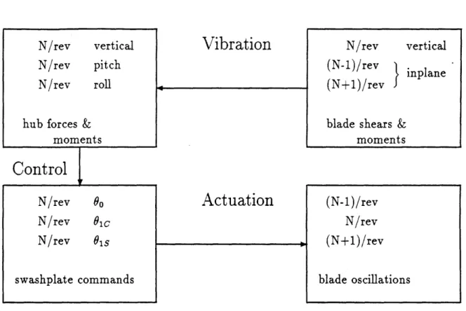
The airloading of a rotor blade is essentially periodic, and can be decomposed as a the sum of harmonics of the rotational frequency. For an N-bladed rotor, only vibration at harmonics of the blade passage frequency, N/rev, will get transmitted to the fuselage. The loading at other rotor harmonics will cancel, due to the net contribution of the N blades [34, pg. 347]. The sources of N/rev airframe vibration include N/rev vertical forces, as well as (N-1)/rev and (N+l)/rev inplane shears and moments. The concept underlying HHC is that reduction of N/rev airframe vibration can be achieved by changing the aerodynamic properties of the blades by oscillations at (N-1)/rev, N/rev, and (N+l)/rev. Figure 1-2 illustrates the transmission of harmonics from the rotating frame to the fixed frame, and vice versa.
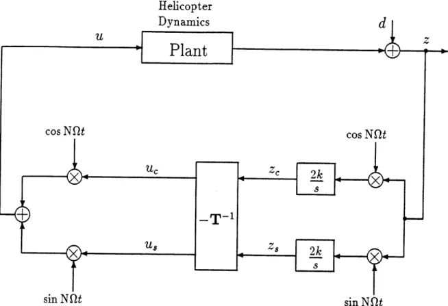
Higher harmonic control can be achieved in either the fixed or rotating systems. Fixed frame actuation is generally implemented through a swashplate. Cosine and sine signals at the N/rev frequency are used to command collective, lateral cyclic, and longitudinal cyclic controls in amplitude and phase. These commands are modulated by the rotor rotation to produce (N-1)/rev, N/rev, and (N+1)/rev variations in blade loading. If an actuation method is implemented in the rotating frame, then cosine and sine signals at (N-1)/rev, N/rev, and (N+1)/rev are commanded explicitly.
Fixed Frame
Rotating Frame
Figure 1-2: Transmission of harmonics.
can be used as feedback signals for higher harmonic control. The relationship be-tween input harmonics and steady hub load harmonics are approximately linear, and can therefore be described by a matrix of constant coefficients [62]. Likewise, the relationship between hub load harmonics and fuselage harmonics are approximately linear, and can also be described by a matrix of constant coefficients. Multiplication of these matrices results in a constant coefficient control response matrix, T, which relates Fourier coefficients of the N/rev input control harmonics to the N/rev output vibration harmonics.
Discrete-Time Higher Harmonic Control Method
One of the earliest higher harmonic control algorithms, suggested by Shaw [62], as-sumes knowledge of the control response matrix, T. A harmonic analysis of the feedback variables is required at each step in the algorithm, in order to obtain the sine and cosine components of the N/rev frequency. The N/rev components are then
multiplied by the inverted control response matrix, T-' , to produce N/rev swashplate
commands to reduce the measured loads. If the control response of the helicopter is essentially quasisteady, the algorithm should produce deadbeat control, and eliminate the N/rev vibration in a single step [24].
Using the quasisteady assumption, the sine and cosine components of the N/rev vibration may be represented by
z = Tu + 10 , (1.2)
where z is a vector of vibration amplitudes, u the vector of N/rev swashplate con-trol amplitudes, and L0 is the vector of uncontrolled vibration amplitudes at zero
swashplate deflection. The vibration levels, 1, are measured at each time step, and a swashplate input, u, is adjusted to cancel the measured disturbance. The resulting control law is
u(n + 1) = u(n) - T-z(n), (1.3)
where the index n denotes the time step. A block diagram of the discrete time higher harmonic control algorithm is shown is Figure 1-3.
Fixed Gain and Scheduled Gain Algorithms
There are several philosophies concerning the control response matrix T. Some re-searchers argue that it is fairly constant with flight conditions, and a fixed gain controller is adequate [63], while others argue that it varies significantly with flight condition and that real time identification will lead to the best controller [48]. These drastically different viewpoints have led to a variety of HHC control methods includ-ing a variety of fixed gain, scheduled gain, and adaptive controllers.
A fixed gain control algorithm is perhaps the most easily implemented algorithm. Only a single control response matrix must be.identified, and gains are precomputed off-line, therefore very little computational effort is required. Fixed gain algorithms, however, cannot adapt to changing flight conditions and may provide suboptimal or inadequate performance.
![Figure 1-1: Human factor vibration requirements (adapted from Figure 1 of Schrage and Peskar [61]).](https://thumb-eu.123doks.com/thumbv2/123doknet/14169035.474313/24.918.184.818.92.598/figure-human-vibration-requirements-adapted-figure-schrage-peskar.webp)
![Figure 1-3: Block diagram of the discrete-time HHC algorithm (adapted from Figure 3 of Hall and Wereley [24]).](https://thumb-eu.123doks.com/thumbv2/123doknet/14169035.474313/39.918.123.799.107.582/figure-block-diagram-discrete-algorithm-adapted-figure-wereley.webp)