To link to this article: DOI:10.1016/j.ijrmms.2015.03.011
http://dx.doi.org/10.1016/j.ijrmms.2015.03.011
This is an author-deposited version published in:
http://oatao.univ-toulouse.fr/
Eprints ID:
14221
To cite this version:
Levasseur, Séverine and Welemane, Hélène and Kondo, Djimédo A
microcracks-induced damage model for initially anisotropic rocks
accounting for microcracks closure. (2015) International Journal of Rock
Mechanics and Mining Sciences. Vol. 77. pp. 122-132. ISSN 1365-1609
O
pen
A
rchive
T
oulouse
A
rchive
O
uverte (
OATAO
)
OATAO is an open access repository that collects the work of Toulouse researchers and
makes it freely available over the web where possible.
Any correspondence concerning this service should be sent to the repository
administrator:
[email protected]
A microcracks-induced damage model for initially anisotropic rocks
accounting for microcracks closure
S. Levasseur
a, H. Welemane
b, D. Kondo
c,naUniversité de Liège, dept. ArGEnCo, Chemin des chevreuils 1, 4000 Liège, Belgium
bUniversité de Toulouse, Ecole Nationale d'Ingénieurs de Tarbes – INP/ENIT EA 1905, 47 avenue d'Azereix, 65016 Tarbes, France cUniversité de Paris VI, Institut d'Alembert, UMR CNRS 7190, 4 place Jussieu, 75005 Paris, France
Keywords: Anisotropic rocks Damage-induced anisotropy Microcracks closure effects Homogenization and micromechanics Argillite
a b s t r a c t
We formulate a new micromechanical damage model for anisotropic rocks. This model accounts not only for the coupling between material initial anisotropy and the damage-induced one, but also for the opening/closure status (the so-called unilateral effects) of evolving microcracks. A closed-form expres-sion of the overall free energy of the microcracked medium is implemented in an appropriate thermodynamics framework to derive a complete damage model for initially anisotropic rocks. The salient features of this model are fully illustrated. Then, its capabilities are demonstrated through an application to a Taiwan argillite subjected to direct tensile loading (including off-axis ones) for which the damage model well captures experimental data (mechanical response, growing damage rocks strength). Finally, the response of the studied rock along a tensile loading followed by an unloading and a reloading in compression is provided in order to illustrate the so-called unilateral damage effects due to microcracks closure.
1. Introduction
The complex inelastic behavior of brittle rock-like materials under mechanical loading generally results from damage phenomena due to evolving microcracks. For the non-linear mechanical response of microcracked materials, Continuum Damage Mechanics (CDM, see, for instance, the textbooks of[1]and[2]) offers an appropriate theo-retical framework. Since several decades, both phenomenological and micromechanical approaches of damage have been proposed. For continuum micromechanics, mention has to be made of several con-tributions dealing with effects of microcracking on materials proper-ties (see, for instance,[3–6]). Formulation of isotropic or anisotropic damage by microcracks growth in rocks or concrete materials has been provided in several studies (see, for instance,[7–19]).
Despite their interest, the above cited models concern only mate-rials which are initially isotropic (in their undamaged state). The purely macroscopic formulation of constitutive models coupling explicitly initial anisotropy and damage-induced one has been only investigated in few recent studies mainly devoted to brittle matrix composites; we refer here to Halm et al.[20](see also[18]and[21]). Mention has also to be made of the purely macroscopic model for an
initially anisotropic rock by Chen et al.[22]. Concerning micro–macro
models, Baste et al.[23]and recently Monchiet et al.[24]proposed
appropriate damage models which couple structural anisotropy and damage by microcracking. Yet, this class of models are limited to damage processes generated by open microcracks growth and need to
be completed in order to properly account for microcracks closure.1To
this end, Goidescu et al.[25]recently established closed-form
expres-sions of the overall free energy of orthotropic materials weakened by microcracks, either open or closed. The present study takes advantage of these very recent results in order to formulate a complete model which fully couples initially anisotropy and evolving unilateral damage due to 2D systems of open or closed microcracks under frictionless conditions.
The paper is organized as follows. We briefly recall the closed-form expression of the macroscopic free energy which will play in the present study the role of a thermodynamics potential for the damaged material. The state laws derived from this potential provide the macro-scopic stress as well as the damage energy release rate (thermody-namic forces conjugated to damage) as a function of the macroscopic strain and the damage variables. By adopting a discrete damage representation defined by the microcracks density parameter, we then propose a damage yield function based on the damage energy release
n
Corresponding author.
E-mail address:[email protected](D. Kondo).
1The corresponding unilateral effects are of paramount importance and
necessary for quasi brittle geomaterials usually subjected to tensile loadings as well as compressive ones.
rate associated to each microcracks family. The corresponding damage surface is illustrated for various configurations of the microdefects system. Finally, we provide the damage evolution law by assuming normality rule and following classical thermodynamics-based proce-dure. This allows us to establish the complete rate formulation of the fully anisotropic constitutive damage law with account of microcracks closure. After a simple calibration step, the proposed model is assessed by comparing its prediction under tensile loading to available data on an argillite studied by Liao et al.[26]. Finally, the ability of the model to also account for microcracks closure effects is fully demonstrated in several cases.
Notations: Standard tensorial notations will be used throughout the paper. Lower underlined case letters will describe vectors, while bold script capital letters will be associated to second-order tensors and mathematical double-struck capital letters to fourth-order ten-sors. The following vector and tensor products are exemplified: ðA !bÞi¼ Aijbj, ðA ! BÞij¼ AikBkj, ðA : BÞij¼ AijklBkl, ðA : BÞijkl¼ Aijpq
Bpqkl, ðA $ BÞijkl¼ AijBkl and ðA $ BÞijkl¼1
2AikBjlþ AilBjk!. Einstein
summation convention applied for the repeated indices and Cartesian coordinates are used. As usual, in the context of continuum micro-mechanics, small (respectively large) characters refer to microscopic (resp. macroscopic) quantities. I and I are, respectively, the second and fourth order identity tensors, the components of the former are
represented by the Kronecker symbol (
δ
ij) while for the latter onehas Iijkl¼ ð1=2Þð
δ
ikδ
jlþδ
ilδ
jkÞ.2. Overall free energy of a 2D anisotropic medium weakened by an arbitrarily oriented system of microcracks
2.1. Representative volume element (r.v.e.)
Micromechanical formulation of a brittle damage model requires first the determination of the effective properties of the microcracked material by using an homogenization procedure.
Let us consider a representative volume element r.v.e.
Ω
of thematerial (seeFig. 1(a)); this is constituted of an elastic orthotropic solid
matrix s (with stiffness tensor Csand occupying a domain
Ω
s) and anarbitrarily oriented system of flat microcracks families (denoted r and
occupying a domain
Ω
r). The latter are assumed open or frictionlessclosed, non-interacting and in dilute concentration. This assumption allows us to fully develop a proper representation of the anisotropic multilinear response of weakened materials and provides basic solu-tions for future developments related to more complex configurasolu-tions
(including for instance interactions between microcracks2).
Micro-cracks of the rth family are characterized by their normal nr and
tangent tr unit vectors, mean length 2lr (the corresponding crack
density is defined as dr¼ NrðlrÞ2 in which Nr is the number of
microcracks of this family per unit surface, see[3]).
This r.v.e. can be subjected either to uniform strain or uniform stress boundary conditions; the latter can take the form:
σ
ðzÞ ! vðzÞ ¼Σ
! vðzÞ; 8 z A ∂Ω
ð1Þin which
σ
denotes the microscopic stress field,Σ
the macroscopicstress, v the outward unit normal to ∂
Ω
and z the vector position.Let us recall that the present study deals with orthotropic materials weakened by arbitrarily oriented microcracks. The sym-metry axes of the matrix correspond to an orthonormal basis ðe1; e2Þ (seeFig. 1) and its stiffness is given by
Cs¼ a1I $ I þa2I$ I þ a3A $ A þ a4ðA $ I þ I $ AÞ ð2Þ
in which A ¼ e1$ e1 denotes the structural fabric tensor and
where a1¼ Cs2222' 2Cs1212; a2¼ 2Cs1212 a3¼ Cs1111þ Cs2222' 2Cs1122' 4Cs1212; a4¼ Cs1122' Cs2222þ 2Cs1212 ð3Þ and Cs1111¼ E1 1'
ν
12ν
21; C s 2222¼ E2 1'ν
12ν
21; Cs1212¼ G12; Cs1122¼ Cs2211¼ν
21E1 1 'ν
12ν
21 ð4ÞE1 and E2 are the Young moduli in the symmetry axes of the
material (respectively to e1and e2), G12is the shear modulus and
ν
12 andν
21 are Poisson ratios related to ðe1; e2Þ (Poisson ratios verify the relation: E1=ν
12¼ E2=ν
21). Equivalently, the complianceSs¼ Cs!' 1
of the matrix is defined as follows in the principal basis ðe1; e2Þ according to the Voigt notation:
Ss¼ 1 E1 ' ν21 E2 0 'ν12 E1 1 E2 0 0 0 1 G12 0 B B B @ 1 C C C A ðe1;e 2Þ : ð5Þ
2.2. Thermodynamics potential of the anisotropic medium weakened by an arbitrarily oriented distribution of microcracks
The main homogenization procedure has been carried out by
Goidescu et al.[25]who performed a direct microfractures
mechanics-based analysis of the anisotropic damaged materials, in the spirit of the studies done in the context of isotropic matrix by[4,6,7,15–17]and others. The macroscopic thermodynamic potential of the anisotropic medium weakened by an arbitrarily oriented distribution of micro-cracks is then obtained as a function of the macroscopic strain tensor E
(the observable state variable) and of the set of damage variables dr
(the internal state variables of the problem), noted d, and associated to
all microcracks family r ranging from 1 to N ¼ Noþ Nc. Assuming a
dilute concentration of microcracks, the solution of the homogeniza-tion problem comes to sum up the contribuhomogeniza-tions of each family of parallel microcracks, namely
Ψ
ðE; dÞ ¼1 2E : C s:E 'X No r ¼ 1drnHrnnðNr:EÞ2þ 2HrntðNr:EÞðTr:EÞ þ HrttðTr:EÞ2o
þX Nc r ¼ 1 dr HrnnHrtt' Hrnt2 Hr nnHr 2 ntðNr:EÞ2þ 2Hr 3 ntðNr:EÞðTr:EÞ þ Hrttð2Hrnt2' Hnnr HrttÞðTr:EÞ2 8 < : 9 = ; ð6Þ
where No represents the number of open microcracks family and
Nc the number of closed cracks. One has Nr¼ Cs:ðnr$ nrÞ and
Fig. 1. (a) Representative volume element in 2D case; (b) crack coordinates system.
2This could be done for instance by considering a Mori–Tanaka like
Tr¼12Cs:ðnr" trþ tr " nrÞ two second order symmetric tensors, Hnnr , Hntr and Httr are scalar parameters that depend on the matrix properties and on the crack orientation
ϕ
r¼ ðe1; nrÞ (see Fig. 1)defined by Hr nn¼ Cð1 % D cos 2
ϕ
r Þ; Hr nt¼ CD sin 2ϕ
r ; Hr tt¼ Cð1 þ D cos 2ϕ
rÞ ð7Þ with scalars C and D being related to the initial stiffness components:C ¼
π
4 ffiffiffiffiffiffiffiffiffiffiffiffi Cs1111 p þpffiffiffiffiffiffiffiffiffiffiffiffiCs2222 ffiffiffiffiffiffiffiffiffiffiffiffiffiffiffiffiffiffiffiffiffiffiffiffiffiffiffiffiffiffiffiffiffiffiffiffiffiffiffiffiffiffiffiffi Cs1111Cs2222% ðCs1122Þ2 q ffiffiffiffiffiffiffiffiffiffiffiffiffiffiffiffiffiffiffiffiffiffiffiffiffiffiffiffiffiffiffiffiffiffiffiffiffiffiffiffiffiffiffiffiffiffiffiffiffiffiffiffiffiffiffiffiffiffiffiffiffiffi 1 Cs1212þ 2 ffiffiffiffiffiffiffiffiffiffiffiffiffiffiffiffiffiffiffiffiffiffiffi Cs1111Cs2222 p % Cs1122 Cs1111Cs2222% ðCs1122Þ2 s D ¼ ffiffiffiffiffiffiffiffiffiffiffiffi Cs 1111 p % ffiffiffiffiffiffiffiffiffiffiffiffiCs 2222 p ffiffiffiffiffiffiffiffiffiffiffiffi Cs1111 p þpffiffiffiffiffiffiffiffiffiffiffiffiCs2222 ð8ÞThe transition between open and closed cracks is described by the criterion function g (see[25]):
gðE; nrÞ ¼ Hr
nnNr:E þ HrntTr:E ð9Þ
If gðE; nrÞ 4 0 microcracks are open, while they are closed if not.
Note that the above formulation(6)can also be written in the
following form:
Ψ
ðE; dÞ ¼1 2E : Chom:E ð10Þ with Chom¼ Cs%X N r ¼ 1 2drBr ð11Þ and Br¼ Cr1Nr" Nrþ Cr2½Nr" Trþ Tr " Nr' þ Cr3Tr" Tr ð12Þ Scalar Cr1, Cr2and Cr3are defined in case of open cracks (index o) as
Cr1 o¼ H r nn; Cr2o¼ H r nt; Cr3o¼ H r tt ð13Þ
while for closed cracks (index c) one has Cr1 c¼ % Hr nnHr 2 nt Hr nnHrtt% Hr 2 nt ; Cr2 c¼ % Hr3 nt Hr nnHrtt% Hr 2 nt ; Cr3 c¼ % Hr ttð2Hr 2 nt% HrnnHrttÞ HrnnHrtt% Hrnt2 ð14Þ
From Eq.(10), the first state law which gives the macroscopic
stress tensor
Σ
can be obtained by derivation:Σ
¼∂Ψ
∂E¼ C
hom:E ð15Þ
With Br being defined by(12), the second state law provides
the expression of the damage energy release rate Fdr(derivative of
Ψ
with respect to dr):Fdr¼ %∂
Ψ
∂dr¼ E : Br:E ð16Þ
Note that the homogenized stiffness tensor Chomand the damage
energy release rate Fdr are both affected by the anisotropic properties
of the solid matrix and also depend on the orientation of the considered microcracks family and on its opening-closure state. This is at the origin of the complex behavior which results from the coupling between initial anisotropy, damage-induced one and uni-lateral behavior as already discussed in Goidescu et al.[25].
2.3. Damage yield function and its illustration
We aim now at formulating the damage evolution laws. To this end, based on the classical thermodynamics arguments, we introduce the following form for the damage criterion associated to each family
of microcracks:
frðFdr; drÞ ¼ Fdr% RðdrÞ ¼ 0 ð17Þ
The scalar function RðdrÞ represents the resistance to the damage
evolution by microcracks growth. A classical choice for brittle damage in the context of an isotropic matrix (see, for instance,[27]), adopted in the present study, consists in (see, for instance,[28])
RðdrÞ ¼ K þ
ξ
dr ð18ÞFollowing then an idea used for geomaterials by Pietruszczak et al.
[29]who introduce a dependency of failure criterion with off-axis, it is proposed to adopt a dependence of the initial threshold with loading orientation
ψ
:K ¼ K0expð
ωψ
Þ ð19ÞK0,
ω
andξ
are material parameters relative to initial threshold and itsevolution with damage;
ψ
corresponds to the angle betweenortho-tropy axis e1 and macroscopic stress principal direction. The
expo-nential term allows us to shift the yield surface from K0according to
the load direction. From(16), it is seen that the damage yield function for each microcracks family r, frðFdr; drÞ ¼ 0, is strongly sensitive to matrix anisotropy, microcrack orientation and their opening-closure state. Once the yield surface is reached, the microcracks density parameter drwill increase as described in(2.4).
To illustrate the overall shape of criterion(17),Figs. 2–5show
for different microcracks orientation
ϕ
r the initial yield surface(virgin state, dr0¼ 0) in the macroscopic strain spaces ðE22; E11Þ,
ðE11; E12Þ and ðE22; E12Þ associated to the axes of orthotropy
(E ¼ E11e1" e1þ E12ðe1" e2þ e2" e1Þ þ E22e2" e2); for
simpli-city, only the source term of K is considered (
ω
¼ 0;K ¼K0¼ 1:2 kJ=m2). Moduli and Poisson ratio are similar to the
one given in Table 1, no initial damage is considered. Various
applications of the complete damage model to an anisotropic rock
will be presented inSection 3.
Regarding these results, several general comments can be done. First, from the mathematical point of view, the thermodynamics
potential
Ψ
is of class C1 on restricted strain space domainsrelated respectively to open and closed microcracks (that is for states E such that gðE; nrÞ 4 0 and gðE; nrÞ o 0 respectively) and of
class C1on the global strain space (see analyses of[30]and[25]);
this allows the definition of a different stiffness Chomaccording to
the microcracks status, while preserving the continuity of the
macroscopic stress
Σ
and force Fdr at the transition between openand closed states; similar features can then be noted inFigs. 2–5
for the initial damage yield surface. Due to the dependence of Fdr
, the yield surface is always hyperbolic despite that it is affected by the state of microcracks; in particular, we note that the damage criterion f ðFdr
; drÞ ¼ 0 systematically exhibits afinite frontier in the open configuration of microcracks, contrary to the closed case; this shows the strong incidence of unilateral effects in the material response that will differ under tensile or compression loading regime, and also the more damaging capabilities of open micro-cracks configurations. Initial yield surface are represented in the strain spaces associated to the axes of orthotropy. In that case, the
differences that can be observed betweenFigs. 2–5come from the
orientation of the microcracks with respect to the matrix anisotropy. In the particular case of a microcracks orientation of
ϕ
r¼ 451, the difference betweenFig. 4(b) and (c) clearly illustrates that this contribution on the yield surface is entirely induced by the amplitude of the matrix anisotropy. A similar remark can bedone betweenFig. 2(b) and (c) (and also betweenFig. 5(b) and (c))
that are not completely symmetric due to the orthotropic elastic properties.
2.4. Damage evolution law and rate form of the constitutive model The damage evolution law is derived by using normality rule for a given family r of microcracks:
_ dr¼
Λ
_r∂f r ∂Fdr¼ _Λ
r ð20Þwhere the damage multiplier
Λ
_r is deduced from the consistencycondition: _ fr¼∂f r ∂E: _E þ ∂fr ∂dr _ dr¼ 0 ð21Þ
It follows the damage evolution in the form: _ dr¼1
ξ
_ Fd r ¼2ξ
E : B r: _E: ð22Þwith the tensor Brbeing defined by(12). Finally, by differentiating the
macroscopic stress–strain relation given by (15), the macroscopic
stress increment is expressed as _
Σ
¼∂Σ
∂E _ E þX N r ¼ 1 ∂Σ
∂dr _ dr¼ Chomt : _E ð23Þwith the tangent operator Chomt ¼ Chom$1 c1E : XN r ¼ 1 Br % Br ! :E ð24Þ
2.5. Integration in a finite element code of the micromechanical model
Even the applications shown in the present study do not necessa-rily require finite element computations, for further numerical simula-tions, the micromechanical damage model has been implemented in the (finite element) code LAGAMINE developed by the University of Liège since the 1980s (with[31,32]). The algorithm of local integration is based on an incremental procedure associated with the rate form of -0.06 -0.04 -0.02 0.00 0.02 0.04 0.06 0.08 0.10 -0.010 -0.005 0.000 0.005 0.010 E22(%) E11(%) open crack closed crack -0.002 0.000 0.002 0.004 0.006 0.008 0.010 -0.02 -0.01 0.00 0.01 0.02 E11(%) E12(%) open crack closed crack -0.02 0.00 0.02 0.04 0.06 0.08 0.10 -0.02 -0.01 0.00 0.01 0.02 E22(%) E12(%) open crack closed crack
Fig. 2. Initial damage yield surface (virgin state, dr
0¼ 0) in the (E22, E11), (E11, E12)
and (E22,E12) strain spaces for a microcrack orientation ϕr¼ 01 (dashed lines denote
the hypersurface separating the open and closed microcracks domains).
-0.06 -0.04 -0.02 0.00 0.02 0.04 0.06 -0.05 -0.03 -0.01 0.01 0.03 E22(%) E11(%) open crack closed crack -0.02 -0.01 0.00 0.01 0.02 -0.03 -0.02 -0.01 0.00 0.01 0.02 0.03 E11(%) E12(%) open crack closed crack -0.30 -0.20 -0.10 0.00 0.10 0.20 0.30 -0.09 -0.06 -0.03 0.00 0.03 0.06 0.09 E22(%) E12(%) open crack closed crack
Fig. 3. Initial damage yield surface (virgin state, dr
0¼ 0) in the (E22, E11), (E11, E12)
and (E22,E12) strain spaces for a microcrack orientation ϕr¼ 201 (dashed lines
stress–strain relation and the strain discretization of the loading path. The scheme for the step j to j þ 1 begins with the initialization of strain tensor and state variables by applying a strain increment
Δ
Ej þ 1:Ej þ 1¼ Ejþ
Δ
Ej þ 1drj þ 1¼ drj; 8 r ¼ 1;…; N (
Then, for r ¼ 1;…; N, the opening-closure condition is examined:
gðE; nrÞ ¼ Hr
nnNr:E þ HrntTr:E ð25Þ
For r ¼ 1;…; N, damage criterion f ðF
dr j; dr
jÞ from Eq. (17) has to be
evaluated with appropriate Cr
1, Cr2and Cr3constants defined by(13)for
open microcracks (gðE; nrÞ 4 0) and (14) for closed microcracks
(gðE; nrÞ r 0): if f ðFdr j; dr jÞ o 0 then drj þ 1¼ drj; if f ðFd r j; dr jÞ Z 0 then
one has to calculate
Δ
drj þ 1 using Eq. (22) and to updatedrj þ 1¼ drjþ
Δ
drj þ 1. Finally, the macroscopic stress tensorΣ
j þ 1 isupdated from Eqs. (11) and (15), so as the tangent operator
ðChomt Þj þ 1with Eq.(24).
3. Applications and validation
As a support for the validation of the new proposed damage model, we consider the anisotropic Taiwan argillite studied by Liao
et al.[26]. This class of materials is commonly considered for
under-ground excavation projects. The Taiwan argillite was formed from slight metamorphism of shale or silty shale. It is composed of about 45% of quartz and 55% clay minerals (illite, chloride for instance), its
dry unit weight is about 27 kN/m3with a very low porosity of about
0.014–0.018. Clear foliation planes are well-developed by recrystalliza-tion of clay minerals.
-0.06 -0.04 -0.02 0.00 0.02 0.04 0.06 -0.05 -0.03 -0.01 0.01 0.03 E22(%) E11(%) open crack closed crack -0.02 -0.01 0.00 0.01 0.02 -0.03 -0.02 -0.01 0.00 0.01 0.02 0.03 E11(%) E12(%) open crack closed crack -0.06 -0.03 0.00 0.03 0.06 -0.09 -0.06 -0.03 0.00 0.03 0.06 E22(%) E12(%) open crack closed crack
Fig. 4. Initial damage yield surface (virgin state, dr0¼ 0) in the (E22, E11), (E11, E12)
and (E22,E12) strain spaces for a microcrack orientation ϕr¼ 451 (dashed lines
denote the hypersurface separating the open and closed microcracks domains).
-0.06 -0.04 -0.02 0.00 0.02 0.04 0.06 -0.05 -0.03 -0.01 0.01 0.03 E22(%) E11(%) open crack closed crack -0.30 -0.20 -0.10 0.00 0.10 0.20 0.30 -0.20 -0.15 -0.10 -0.05 0.00 0.05 0.10 0.15 0.20 E11(%) E12(%) open crack closed crack -0.08 -0.05 -0.02 0.01 0.04 -0.06 -0.04 -0.02 0.00 0.02 0.04 E22(%) E12(%) open crack closed crack
Fig. 5. Initial damage yield surface (virgin state, dr
0¼ 0) in the (E22, E11), (E11, E12)
and (E22,E12) strain spaces for a microcrack orientation ϕr¼ 701 (dashed lines
denote the hypersurface separating the open and closed microcracks domains).
Table 1
Model parameters for the Taiwan argillite.
E1 E2 ν12 G12 K0 ω ξ
3.1. Identification of the model
Liao et al.[26]investigated the tensile response of such argillite
under axis and off-axis loads by employing a servocontrolled material testing machine (model MTS 810) with tensile grip, which is a computer controlled machine with 250 kN load capacity. Denoting ðx; yÞ the orthonormal basis corresponding to the testing device frame, several uniaxial tests along y-axis have been performed for different loading orientations
ψ
¼ ðx; e1Þ ¼ ðy; e2Þ with ðe1; e2Þ being the prin-cipal axes of this transversely isotropic rock (seeFig. 6). For each test, displacements have been measured by LVDT, strain by extensometer. A plane strain approach is adopted for the modeling of the studied rock. Owing to symmetry considerations, only one quarter of the sample is considered. Vertical displacements are locked on the bottom (y¼0) and horizontal displacements are locked on the left side (x¼0). The tensile loadingΣ
yyis applied on the top of the sample (Fig. 6). All simulations are made by using for the damage representation a discretization of N¼60 families of microcracks with uniform distribu-tion of unit normals nr, that isϕ
r¼ ðe1; nrÞ ¼
π
ðr # 1Þ=N; 8 r ¼ 1; 60.The four elastic constants can be determined from the linear part of the laboratory tests. E1is directly estimated from (
Σ
yy,Eyy) curve for the test atψ
¼ 901; E2is directly estimated from (Σ
yy,Eyy)curve for the test at
ψ
¼ 01; G12andν
12are calibrated to reproducein average (
Σ
yy, Exx) and (Σ
yy, Eyy) curves for all the tests. The experimental results clearly put also in evidence the depen-dence of the damage evolution with the orientation of foliation planes (Fig. 7). Especially, we note that stress–strain curves exhibitnon-linearity before failure for low inclination
ψ
, whereas the responsesare quite linear for high inclination
ψ
. Considering an initial isotropic damage distribution (initial state such that dr0¼ 0:01; 8 r ¼ 1; 60), the two remaining model parameters have then been identified from the variation of the initial damage threshold with loading orientation thatfollows the exponential relation (19) with K0¼ 0:2 kJ=m2 and
ω
¼ 0:043 (Fig. 8). The same evolution of damage is assumed for allthe tests through the definition of the
ξ
parameter of Eq.(18).Table 1summarizes the results of the calibration procedure for the Taiwan argillite.
3.2. Simulation of uniaxial tensile test on Taiwan argillite
The results of the above model calibration are shown in
Figs. 9 and 10. In addition to the overall response, the orientational
average damage d ¼ ð1=NÞ PN
r ¼ 1d
r, induced by the load, is also
depicted. It is observed that the stress–strain curves
Σ
yy–Eyy andtensile strengths are well captured by the model (except maybe for
the case
ψ
¼ 301 for which experimental data seems less accurate); onthe other hand, the predicted evolutions of the damage seem realistic. Especially, the model is able to capture the experimental trends that can be related to some transition with the change of the loading angle
ψ
. For the tensile loads, microcracks develop mainly along the normaldirection to loading, so along x-axis in our example; in other words, the orientation of the microcracks family with the highest density is
ϕ
r¼ 901 whenψ
¼ 01. The theoretical approach provides a differentinteraction between initial anisotropy and damage induced one: for
load with low inclination
ψ
, damage appears earlier and growgradually causing a more pronounced non-linear behavior of argillite; on the contrary for high inclination, damage occurs later and its propagation is rather sudden. Numerically, the latter case leads rapidly Fig. 6. Uniaxial tensile test and anisotropy orientation.
0 2 4 6 8 10 12 -100 -50 0 50 100 150 200 yy(MPa) (*.10-6) 0° 30° 45° 60° 90° 75° 0° 30° 45° 60° 90° 75° Eyy Exx 0 0.2 0.4 0.6 0.8 1 0 10 20 30 40 yy(MPa) Eyy(*.10-6) 0° 30 45 60 90° 75° ° ° °
Fig. 7. Experimental stress–strains responses for different loading orientations ψ ¼ 01, 301, 451, 601, 751, 901 (Σyythe axial stress, Eyythe axial strain, Exxthe radial
strain): (a) global response, (b) zoom on linear elastic part.
0 2 4 6 8 10 12 0 15 30 45 60 75 90 yy(MPa) (°)
Fig. 8. Variation of axial stress Σyycorresponding to the initial damage threshold
with loading orientation ψ: experimental results (symbols) and model calibration (full line).
to the non-convergence of the model due to the strong damage levels reached.
By analogy to stress paths in elasto-plasticity theory, a “damage path” can be drawn in the strain space associated to orthotropy axes (Fig. 11). Two loading orientations
ψ
have been considered; initial and final damage yield surfaces are also depicted as a reference, consider-ing in each case one family of microcracks correspondconsider-ing to the preferential orientation (maximum density) obtained under tensileloading (that is
ϕ
r¼ 901 forψ
¼ 01 andϕ
r¼ 451 forψ
¼ 451). Evenfor elastic behavior,Fig. 11clearly puts in evidence the differences
between axis and off-axis loads induced in the initial principal strain space. It is also observed that microcracks remain in their open status for both tests. Also, once strain state reaches damage criterion in one direction, the damage criterion varies linearly with damage both in open and closed crack domains and similarly in all directions due to
scalar resistance considered in Eq. (18). Consequently, the final
damage surface is homothetic to the initial one.
Damage coupling with matrix anisotropy affects also the overall
compliance tensor Shom¼ Chom!!1. Variations of the components of
0.01
0.03
0.05
0.07
0.09
0.11
0.13
0.15
0
0.5
1
1.5
2
2.5
3
3.5
4
-50
0
50
100
150
200
yy(MPa)
(*.10
-6)
E
yy0°
E
xx0.01
0.03
0.05
0.07
0.09
0.11
0.13
0.15
0
0.5
1
1.5
2
2.5
3
3.5
4
-50
0
50
100
150
200
yy(MPa)
(*.10
-6)
30°
E
yyE
xx0.01
0.03
0.05
0.07
0.09
0.11
0.13
0.15
0
0.5
1
1.5
2
2.5
3
3.5
4
-50
0
50
100
150
200
yy(MPa)
(*.10
-6)
45°
E
yyE
xxFig. 9. Model predictions of the argillite stress–strain responses and mean damage for 3 loading axis orientations: (a) ψ ¼ 01, (b) ψ ¼ 301, (c) ψ ¼ 451 (symbols: lab measurements; full lines: stress–strain numerical results; dash lines: damage numerical results). 0.010 0.025 0.040 0.055 0.070 0.085 0.100 0 0.5 1 1.5 2 2.5 3 3.5 4 -100 -50 0 50 100 150 200 250 yy(MPa) (*.10-6) Eyy Exx 0.010 0.025 0.040 0.055 0.070 0.085 0.100 0 2 4 6 8 10 -100 -50 0 50 100 150 200 250 yy(MPa) (*.10-6) Eyy Exx 0.010 0.025 0.040 0.055 0.070 0.085 0.100 0 2 4 6 8 10 12 14 -100 -50 0 50 100 150 200 250 yy(MPa) (*.10-6) Eyy Exx
Fig. 10. Model predictions of the argillite stress–strain responses and mean damage for 3 loading axis orientations: (a) ψ ¼ 601, (b) ψ ¼ 751, (c) ψ ¼ 901 (symbols: lab measurements; full lines: stress–strain numerical results; dash lines: damage numerical results).
this tensor in the material basis ðe1; e2Þ of anisotropy and in the basis ðx; yÞ (Eq.(5)) associated to the loading are shown inFig. 12for two loading cases:
Shom¼
Shom1111 Shom1122 Shom1211 Shom
1122 Shom2222 Shom1222
Shom1211 Shom1222 Shom1212 0 B B @ 1 C C A ðe1;e2Þ ¼ Shom
xxxx Shomxxyy Shomxyxx
Shom
xxyy Shomyyyy Shomxyyy
Shom
xyxx Shomxyyy Shomxyxy
0 B B B @ 1 C C C A ðx;yÞ ð26Þ
This figure shows that when
ψ
¼ 01, microcracks evolve alongbedding plane affecting mainly S2222hom (or Syyyyhom) component of Shom
tensor. When
ψ
¼ 451, microcracks still evolve along x-axis whichis now different from the bedding plane. As a result, the evolution of S2222hom (or Syyyyhom) component is quite similar for both loading orientations, whereas effects on S1111hom and S1212hom are more
signifi-cant when
ψ
¼ 451. However, in the basis ðx; yÞ, the evolution ofSyyyyhom is more pronounced than the evolution of Sxxxxhom due to a
strong coupling between matrix anisotropy and damage induced
anisotropy (see Appendix). Note also that in case
ψ
¼ 451, earliernon-convergence of the model is caused by an intense damage
that occurs more suddenly (as already observed inFigs. 9 and 10).
To be more illustrative, let us examine the effective Young modulus EeffðvÞ de
fined for any direction of unit vector v by[33]: EeffðvÞ ¼ v # v : Sh hom:v # vi$1
ð27Þ
Fig. 13presents the distribution of such modulus normalized by its
initial orthotropic value EsðvÞ (respectively derived for compliance
tensor Ss) for the two studied loading cases; the initial values
correspond to unit circles. When damage occurs, moduli are deg-raded. However, because of a strong coupling between matrix anis-otropy and damage induced anisanis-otropy, these degradations differ
from one direction to the others. In case of
ψ
¼ 01, loading directioncorresponds to an initial principal axis; then, structural and induced
anisotropies remain collinear. In case of
ψ
¼ 451, loading directiondoes not correspond to the anisotropy axis, so we can observe the competition between initial anisotropy (with axes ðe1; e2Þ) and ind-uced anisotropy (with axes ðx; yÞ) since microcracks mainly develop along axis x.
3.3. Microcracks closure effect: tension–compression loading In order to investigate microcracks closure effects on the macro-scopic behavior, we consider that one has to perform the unilateral effect through the modeling of tensile loading followed by an unloading and then reloading in compression. The objective is to evaluate how progressive closure of open microcracks (initially generated during the tension loading step) affects the material response during the compression phase. Note that the response under tension loading is the same as described above.
Fig. 14presents the axial stress–strain curve
Σ
yy–Eyycorrespondingto the above tension-compression loading path for the axis case
ψ
¼ 01. In the samefigure, is provided the evolution of the averagedamage d with axial strain Eyy. The obtained stress–strain curve shows continuous response at the tension-compression transition (when axial stress is equal to zero corresponding to the opening/closure transition) despite the discontinuity of the macroscopic elastic proper-ties at this transition.
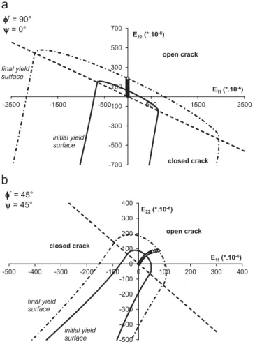
-700 -500 -300 -100 100 300 500 700 -2500 -1500 -500 500 1500 2500 E22(*.10-6) E11(*.10-6) open crack closed crack final yield surface initial yield surface r= 90° = 0° -500 -400 -300 -200 -100 0 100 200 300 400 -500 -400 -300 -200 -100 0 100 200 300 400 E22(*.10-6) E11(*.10-6) open crack closed crack final yield surface initial yield surface r= 45° = 45°
Fig. 11. Tensile loading path in ðE22; E11Þ orthotropic strain space (diamond
symbols) for two loading orientations ψ ¼ 01 and 901 with initial (d0r¼ 0.01, full
lines) and final (drðψ ¼ 01Þ ¼ 0:15 and drðψ ¼ 451Þ ¼ 0:12, dash lines) damage yield surfaces for the related preferential microcrack orientations: (a) axis-load: ψ¼ 01; ϕr¼ 901, (b) off-axis load: ψ ¼ 451; ϕr¼ 451. 0.00 0.03 0.06 0.09 0 50 100 150 200 Shom(GPa-1) Eyy(*.10-6) 0.00 0.03 0.06 0.09 0 50 100 150 200 Shom(GPa-1) Eyy(*.10-6)
Fig. 12. Evolution of the components of the homogenized tensor Shomin (a)
aniso-tropic basis ðe1; e2Þ and (b) calculation basis ðx; yÞ with axial strain: lines refer to
It has been noted that depending of the loading regime (tension or compression phase), microcracks do not grow in the same directions. Indeed, as indicated before, the preferential microcrack orientation during the first tensile phase is along axis x (the family of cracks with
orientation
ϕ
r¼901 exhibits the maximum density). On the contrary,during compression reloading phase, the most evolved microcracks
are oriented at about
ϕ
r¼451 (see[28]). Furthermore, the status ofthese families differs according to the load (open during the ten-sile phase, closed during compression). Representation of the tension-compression loading path in strain space with related preferential damage yield surfaces allows us to explain the different stages of damage (seeFigs. 14 and 15). Naturally, as long as tensile loading does not reach damage criterion for the family of microcracks with
ϕ
r¼901, damage is constant to initial isotropic value d0¼0.01 andstress–strain relation is linear; microcracks are all open in this case. After this yield surface is reached, damage evolves and generates the non-linearity of stress–strain curve due to the degradation of stiffness tensor. Moreover, the evolving damage induces growth of damage
surface for the main microcracks family (
ϕ
r¼901). During unloadingphase, the strain path comes into the elastic convex domain with a constant damage level. When compression load is applied, most of microcracks get closed (only few families with normal close to x
remain open, see[28]); this modification of the defects status induces
a non-linearity (change of the overall elasticity) but without damage
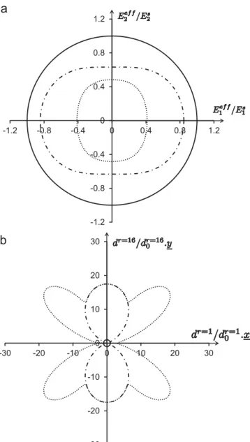
evolution as shown inFig. 16which displays the distributions of the
normalized effective Young modulus and of the normalized damage
dr=dr0after tensile loading and compression reloading. Damage
evo-lves again when the path reaches the yield surface of the microcracks with orientation
ϕ
r¼451 that are in the closed state. Note that similarresults are obtained whatever the anisotropy orientation
ψ
. Even ifsuch test has not been performed for now on the studied argil-lite, it should be underlined that predictions of the model stand in -1.2 -0.8 -0.4 0 0.4 0.8 1.2 -1.2 -0.8 -0.4 0 0.4 0.8 1.2
= 0°
-1.2 -0.8 -0.4 0 0.4 0.8 1.2 -1.2 -0.8 -0.4 0 0.4 0.8 1.2= 45°
Fig. 13. Evolution of the distribution of the normalized effective Young modulus Eeff
ðvÞ=EsðvÞ: (a) axis-load: ψ ¼ 01, (b) off-axis load: ψ ¼ 451 (full lines: initial unit circle; dash lines: final distribution of normalized properties).
0.01 0.04 0.07 0.1 0.13 0.16 -10 -8 -6 -4 -2 0 2 4 -400 -300 -200 -100 0 100 200 yy(MPa) Eyy(*.10-6)
Fig. 14. Simulation of tensile loading followed by unloading and reloading in compression for axis loading (ψ ¼ 01) (full line: axial stress–strain curve Σyy–Eyy;
dashed line: evolution of mean damage d with axial strain).
-700 -500 -300 -100 100 300 500 700 -2500 -1500 -500 500 1500 2500 Eyy(*.10-6) Exx(*.10-6) open crack closed crack final yield surface initial yield surface r= 90° = 0° -500 -400 -300 -200 -100 0 100 200 300 400 -500 -400 -300 -200 -100 0 100 200 300 400 Eyy(*.10-6) Exx(*.10-6) open crack closed crack final tension yield surface initial yield surface final compression yield surface r= 45° = 0°
Fig. 15. Tensile unloading–compression loading path in ðEyy; ExxÞ strain space
(diamond symbols) for axis load ψ ¼ 01: initial (d0r¼0.01, full lines) and final (after
tension load drðϕr¼ 901Þ ¼ 0:174 and drðϕr¼ 451Þ ¼ 0:078, dash lines; after com-pression load drðϕr¼ 901Þ ¼ 0:174 and drðϕr¼ 451Þ ¼ 0:236, dot lines) damage yield surfaces and opening-closure hypersurfaces for the related preferential microcrack orientation ((a) ϕr¼901; (b) ϕr¼451).
agreement with experimental tendencies obtained for a sandstone
[34]or for concrete materials[35].
4. Conclusions
Taking advantage of the recent study by Goidescu et al.[25], a full 2D anisotropic micromechanical damage model has been formulated for initially anisotropic rocks. The originality of the formulation mainly lies in accounting for the coupling between the damage-induced anisotropy and the orthotropy of the solid matrix and in the characterization of unilateral effects of evolving microcracks. Applied to argillite, the model predicts that the initial anisotropy of the rock strongly affects the damage initiation and growth and subsequently the macroscopic response of the material through the stiffness de-gradation. Furthermore, depending of the orientation of the load with respect to the material symmetry axis, damage can occur gra-dually or suddenly, leading either to non-linear or to quasi-linear be-havior of the studied argillite, as observed during experiments. Microcracks opening/closure effects are also illustrated through the
material response under a tension-compression test. Moreover, the systematic analysis of the damage criterion in strain space provides an appropriate description of damage evolution process and the various coupling effects which accompanied it.
Further investigations need now to be conducted to complete the validation, especially regarding the comparison with experimental data for complex loads including a change in the microcracks status (for instance tension followed by compression). Moreover, the repre-sentation should be improved by the introduction of inelastic strain of the material induced by friction sliding still in micromechanical fram-ework. Again, it will be interesting to account by this way of the inte-ractions between closure effects, initial anisotropy and friction sliding and provide an enriched representation of the behavior of microcrac-ked materials.
Acknowledgments
The authors would like to thank the F.R.S.-FNRS, the national funds of scientific research in Belgium, for their financial support in the FRFC project.
Appendix A. Formulation of homogenized stiffness tensor Chom
According to Goidescu et al. [25], the homogenized stiffness
tensor can be written as a function of the fabric tensor A and crack
orientation nras follows: Chom¼ CsþX N r ¼ 1 dr 2
χ
r1I " I þ 2χ
r2A " A þχ
r3ðI " A þ A " IÞ þ 2χ
r4nr" nr" nr " nr þχ
r5ðI "nr" nrþ nr" nr " IÞ þχ
r6ðI " nr" nrþ nr" nr" IÞ þχr7 2½ðnr " nr& A þ A & nr " nrÞ " I þ I " ðnr" nr& A þ A & nr" nrÞ' þχ
r8ðnr" nr" A þ A " nr" nrÞ þχr9 2½ðnr " nr& A þ A & nr " nrÞ " A þ A " ðnr" nr& A þ A & nr" nrÞ' þχr10 2½ðnr" nr& A þ A & nr" nrÞ " nr" nr þ nr " nr " ðnr" nr& A þ A & nr" nrÞ' 2 6 6 6 6 6 6 6 6 6 6 6 6 6 6 6 6 6 6 6 6 6 6 6 4 3 7 7 7 7 7 7 7 7 7 7 7 7 7 7 7 7 7 7 7 7 7 7 7 5 ðA:1Þ in which the coefficientsχ
rpðCs; nr; AÞp ¼ 1;10 are given by Goidescu
et al.[25]according to microcrack status (open or closed). From this
formulation, interactions between anisotropies can be explicitly
defined through combinations of E, A and nr " nr. Then, one could
distinguish three kinds of coupling between the initial anisotropy and the microcracks induced one: (i) isotropic-like coupling thanks to terms of coefficients
χ
r1,χ
r2andχ
r3that preserve the initial orthotropyof the material; (ii) weak anisotropic coupling thanks to terms of coefficients
χ
r4,χ
r5 andχ
r6 that account for the loss of materialorthotropy through tensorial terms identical to isotropy; primary anisotropy is only taken into account in constant
χ
r4,χ
r5 andχ
r6definitions; (iii) strong anisotropic coupling thanks to all other terms that introduce complex anisotropy through combinations of orienta-tional effects of nr, A and E.
References
[1]Krajcinovic D. Damage mechanics. In: Achenbach JD, et al., editors. Applied mathematics and mechanics, vol. 41. Amsterdam: Elsevier Science Publishers B.V.; 1996.
[2]Lemaitre J, Chaboche J-L. Mechanics of solid materials. Cambridge: Cambridge University Press; 1990. -1.2 -0.8 -0.4 0 0.4 0.8 1.2 -1.2 -0.8 -0.4 0 0.4 0.8 1.2 -30 -20 -10 0 10 20 30 -30 -20 -10 0 10 20 30
Fig. 16. Evolution of (a) the distribution of the normalized effective Young modulus EeffðvÞ=EsðvÞ and (b) the distribution of the normalized damage dr
=dr0after tensile
loading (dash lines) and compression reloading (dot lines) (full lines refer to initial states – unit circles).
[3]Budiansky B, O'Connell R. Elastic moduli of a cracked solid. Int J Solids Struct 1976;12:81–97.
[4]Horii H, Nemat-Nasser S. Overall moduli of solids with microcracks: load-induced anisotropy. J Mech Phys Solids 1983;31:155–71.
[5]Zimmermann RW. Compressibility of sandstones. In: Chilingarian GV, editor. Developments in petroleum science, vol. 29. Amsterdam, Elsevier: Elsevier Science Publishers B.V.; 1991.
[6]Kachanov M. Elastic solids with many cracks related problems. In: Hutchinson J, Wu T, editors. Advances in applied mechanics, vol. 30. New-York: Academic Press; 1993. p. 259–445.
[7]Andrieux S, Bamberger Y, Marigo J-J. Un modèle de matériaux microfissuré pour les roches et les bétons. J Méca Théor Appl 1986;5:471–513.
[8]Costanzo F, Boyd J, Allen D. Micromechanics and homogenization of inelastic composite materials with growing cracks. J Mech Phys Solids 1996;44:333–70. [9]David EC, Brantut N, Schubnel A, Zimmerman RW. Sliding crack model for nonlinearity and hysteresis in the uniaxial stress–strain curve of rock. Int J Rock Mech Min Sci 2012;52:9–17.
[10]Dormieux L, Kondo D. Stress-based estimates and bounds of effective elastic properties: the case of cracked media with unilateral effects. Comput Mater Sci 2009;46(1):173–9.
[11]Ju JW, Lee X. Micromechanical damage model for brittle solids. Part 1: tensile loading. Part 2: compressive loading. Mech Mater 1991;117(7):1495–536. [12]Kachanov ML. A microcrack model of rock inelasticity. Part 1: frictional sliding
on microcracks. Part 2: propagation of microcracks. Mech Mater 1982;1: 19–41.
[13]Levasseur S, Collin F, Charlier R, Kondo D. A two scale anisotropic damage model accounting for initial stresses in microcracked materials. Eng Fract Mech 2011;78.
[14]Levasseur S, Collin F, Charlier R, Kondo D. A micro–macro approach of permeability evolution in rocks excavation damaged zones. Comput Geotech 2013;49:245–52.
[15]Pensée V, Kondo D. Micromechanics of anisotropic brittle damage: compara-tive analysis between a stress based and a strain based formulation. Mech Mater 2003;35:747–61.
[16]Pensée V, Kondo D, Dormieux L. Micromechanical analysis of anisotropic damage in brittle materials. J Eng Mech 2002;128:889–97.
[17]Zhu QZ, Kondo D, Shao JF, Pensée V. Micromechanical coupling of anisotropic damage in brittle rocks and application. Int J Rock Mech Min Sci 2008;45: 467–77.
[18]Dragon A, Halm D. Damage Mechanics - Some modelling challenges. Polish Academy of Sciences. Warsaw: IPPT PAN; 2004.
[19]Dormieux L, Kondo D, Ulm F-J. Microporomechanics. Chichester: John Wiley & Sons Ltd; 2006.
[20]Halm D, Dragon A, Charles Y. A modular damage model for quasi-brittle solids - interaction between initial and induced anisotropy. Arch Appl Mech 2002;72:498–510.
[21]Cazacu O, Soare S, Kondo D. On modeling the interaction between initial and damage-induced anisotropy in transversely isotropic solids. Math Mech Solids 2007;12(3):305–18.
[22]Chen L, Shao JF, Zhu QZ, Duveau G. Induced anisotropic damage and plasticity in initially anisotropic sedimentary rocks. Int J Rock Mech Min Sci 2012;51: 13–23.
[23]Baste S. Inelastic behaviour of ceramic–matrix composites. Compos Sci Technol 2001;61:2285–97.
[24]Monchiet V, Gruescu C, Cazacu O, Kondo D. A micromechanical approach of crack-induced damage in orthotropic media: application to a brittle matrix composite. Eng Fract Mech 2012;83:40–53.
[25]Goidescu C, Welemane H, Kondo D, Cruescu C. Microcracks closure effects in initially orthotropic materials. Eur J Mech A/Solids 2013;37:172–84. [26]Liao JJ, Yang MT, Hsien HY. Direct tensile behavior of a transversely isotropic
rock. Int J Rock Mech Min Sci 1997;34(5):837–49.
[27]Marigo J-J. Modeling of brittle and fatigue damage for elastic material by growth of microvoids. Eng Fract Mech 1985;21(4):861–74.
[28] Goidescu C. Caractérisation et modélisation de l'endommagement par micro-fissuration des composites stratifiés – Apports des mesures de champs et de l'homogénéisation [Ph.D. thesis]. Université de Toulouse; 2011.
[29]Pietruszczak S, Lydzba D, Shao JF. Modelling of inherent anisotropy in sedimentary rocks. Int J Solids Struct 2002;39:637–48.
[30]Cormery F, Welemane H. A stress-based macroscopic approach for micro-cracks unilateral effect. Comput Mater Sci 2010;47:727–38.
[31] Charlier R. Approche unifiée de quelques problèmes non linéaires de méca-nique des milieux continus par la méthode des éléments finis (grandes déformations des métaux et des sols, contact unilatéral de solides, conduction thermique et écoulements en milieu poreux [Ph.D. thesis]. Université de Liège; 1987.
[32] Habraken AM. Contribution à la modélisation du formage des métaux par la méthodes des éléments finis [Ph.D. thesis]. Université de Liège; 1989. [33]Hayes M. Connexions between the moduli for anistropic elastic materials.
J Elast 1972;2(2):135–41.
[34]Ikogou S. Etude expérimentale et modélisation du comportement d’un grès. Ph.D. thesis. France: Université de Lille 1; 1990.
[35]Reinhardt HW. Fracture mechanics of elastic softening materials like concrete. Heron 1984;29(2).