Publisher’s version / Version de l'éditeur:
Canadian Acoustics, 33, September 3, pp. 68-69, 2005-10-01
READ THESE TERMS AND CONDITIONS CAREFULLY BEFORE USING THIS WEBSITE.
https://nrc-publications.canada.ca/eng/copyright
Vous avez des questions? Nous pouvons vous aider. Pour communiquer directement avec un auteur, consultez la
première page de la revue dans laquelle son article a été publié afin de trouver ses coordonnées. Si vous n’arrivez pas à les repérer, communiquez avec nous à PublicationsArchive-ArchivesPublications@nrc-cnrc.gc.ca.
Questions? Contact the NRC Publications Archive team at
PublicationsArchive-ArchivesPublications@nrc-cnrc.gc.ca. If you wish to email the authors directly, please see the first page of the publication for their contact information.
NRC Publications Archive
Archives des publications du CNRC
This publication could be one of several versions: author’s original, accepted manuscript or the publisher’s version. / La version de cette publication peut être l’une des suivantes : la version prépublication de l’auteur, la version acceptée du manuscrit ou la version de l’éditeur.
Access and use of this website and the material on it are subject to the Terms and Conditions set forth at
Vertical flanking sound transmission via the wall-floor junction in wood
framed construction
Quirt, J. D.; Nightingale, T. R. T.; Halliwell, R. E.
https://publications-cnrc.canada.ca/fra/droits
L’accès à ce site Web et l’utilisation de son contenu sont assujettis aux conditions présentées dans le site LISEZ CES CONDITIONS ATTENTIVEMENT AVANT D’UTILISER CE SITE WEB.
NRC Publications Record / Notice d'Archives des publications de CNRC:
https://nrc-publications.canada.ca/eng/view/object/?id=8cdfa984-c457-41da-a9b0-f157efa1d25f https://publications-cnrc.canada.ca/fra/voir/objet/?id=8cdfa984-c457-41da-a9b0-f157efa1d25fhttp://irc.nrc-cnrc.gc.ca
Ve r t ic a l fla nk ing sound t ra nsm ission via
t he w a ll-floor junc t ion in w ood fra m e d
c onst ruc t ion
Q u i r t , J . D . ; N i g h t i n g a l e , T . R . T . ; H a l l i w e l l , R . E .
N R C C - 4 9 2 5 3
A v e r s i o n o f t h i s d o c u m e n t i s p u b l i s h e d i n
/ U n e v e r s i o n d e c e d o c u m e n t s e t r o u v e
d a n s : C a n a d i a n A c o u s t i c s , v . 3 3 , n o . 3 ,
S e p t . 2 0 0 5 , p p . 6 8 - 6 9
V
ERTICAL FLANKING SOUND TRANSMISSION
VIA THE WALL
-
FLOOR JUNCTION IN WOOD FRAMED CONSTRUCTION
J. David Quirt, Trevor R.T. Nightingale, Robin E. Halliwell
Institute Research in Construction, National Research Council, Ottawa, K1A 0R6, Canada
1. INTRODUCTION
This paper presents factors controlling transmission of impact (footstep) sound from the floor of one room, to the room below, as indicated in Figure 1, and outlines how transmission data were used to develop a simplified design guide 1 that provides estimates of “Apparent Normalized Impact Sound Pressure Level” which is the combined transmission due to all direct and flanking paths.
A t t e n u a t i o n w i t h D i s t a n c e S t r u c t u r a l I m p e d a n c e P o w e r i n j e c t e d b y S o u r c e S t r u c t u r a l A t t e n u a t i o n F l a n k i n g S o u n d P o w e r R a d i a t i o n I m p e d a n c e J u n c t i o n A t t e n u a t i o n D i r e c t S o u n d P o w e r A t t e n u a t i o n w i t h D i s t a n c e S t r u c t u r a l I m p e d a n c e P o w e r i n j e c t e d b y S o u r c e S t r u c t u r a l A t t e n u a t i o n F l a n k i n g S o u n d P o w e r R a d i a t i o n I m p e d a n c e J u n c t i o n A t t e n u a t i o n D i r e c t S o u n d P o w e r
Figure 1: Transmission paths for impact sound.
The procedures to determine the “Direct Normalized Impact Sound Pressure Level” (due to transmission through just the floor-ceiling assembly) and the “Flanking Normalized Impact Sound Pressure Level” (due to flanking transmission via each wall below) are given elsewhere 2.
(a) (b) (c)
(a) (b) (c)
(a) (b) (c)
Figure 2: Construction details of the 3 wall/floor systems. Joists were oriented (a) parallel to the wall, (b) perpendicular to the wall, and (c) with joists continuous across the wall, perpendicular to it. The basic procedure is to determine the path transmissions and then obtain estimates of the apparent sound insulation by summing the energy transmitted via the direct path through the floor-ceiling assembly and all the flanking paths involving the four wall-floor junctions. Results in this paper apply to wood-framed constructions, typical of those shown in Figure 2. Construction details are given elsewhere 2.
2.
RESULTS & DISCUSSION
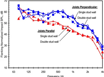
Impact sound transmission was measured in accordance with ASTM E1007, except all source positions were 2.2 m from the wall. Additional tests were made to characterize structure borne propagation across the floor. Figure 3 shows that the Flanking NISPL depends on the joist orientation relative to the wall. However, the difference between single- and double-stud wall framing was small, so an average over the wall-framing cases can be used to create an estimate of flanking for the design guide.
10 20 30 40 50 60 70 63 125 250 500 1k 2k 4k Frequency, Hz Flanking N o rm alized Im pact SPL, dB Joists Parallel
Double stud wall
Single stud wall
Joists Perpendicular:
Single stud wall
Double stud wall
Figure 3: Flanking-NISPL for a single flanking wall with 2 layers of gypsum board, impact source 2.2 m from the wall.
-10 -8 -6 -4 -2 0 2 4 6 8 10 63 125 250 500 1000 2000 4000 Frequency, Hz Change in Flanking Im pact SPL, dB 1.2m closer to junction joists parallel 1.2m closer to junction joists perpendicular 1.2m farther from junction joists perpendicular
1.2m farther from junction joists parallel
Figure 4: Change in Flanking-NISPL for one wall due to moving an impact source on the bare OSB floor surface
Flanking-NISPL for the path shown in Figure 1 increases as the source moves towards the floor-wall junction, as shown in Figure 4. The change is greater when the floor joists are parallel to the junction because attenuation across the floor is stronger in that direction.
A design estimate is obtained by considering the effect of all paths for the four walls in the room below. By evaluating a number of scenarios, it was found that different positions of the impact source on the floor above had little effect on total sound power transmitted by the combination of the four flanking paths. Figure 5 shows estimates of the Flanking-NISPL due to all four flanking walls, and compares these with direct transmission through the floor.
20 30 40 50 60 70 80 63 125 250 500 1k 2k 4k Frequency, Hz D
irect and Flanking Im
pact SPL, dB Flanking (4 walls) Single layer direct attached Flanking (4 walls) Double layer direct attached Direct path Flanking (4 walls) Single layer
resilient channels used on all walls
Figure 5: NISPL due to the direct path, or combined flanking paths for all four walls in the room below
-30 -25 -20 -15 -10 -5 0 5 10 15 20 25 63 125 250 500 1k 2k 4k Frequency, Hz Change in Im
pact Sound Pressure Level, dB
Flanking (floor to wall below) Joists Parallel
Direct path (floor to ceiling) Flanking (floor to wall below)
Avg. Joists Perpendicular
Improving Impact Sound Insulation
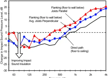
Figure 6: Effect of a 25 mm thick gypsum concrete topping bonded to the OSB subfloor
Changing the floor surface can alter impact sound
transmission in two ways – changing the power injected into the floor by the impact, and changing transmission across the floor surface to the floor-wall junction. Figure 6 shows that adding a 25 mm layer of gypsum concrete reduces the
ISPL at the lower frequencies. The ISPL is significantly increased at higher frequencies because gypsum concrete is harder than OSB and more power is transferred from the tapping machine. Adding this topping also significantly changes vibration propagation across the floor surface (so in Figure 6, the change in direct transmission differs
significantly from that for flanking and the flanking change is different for the two joist orientations).
In practice the gypsum concrete topping will have a floor covering that will add a compliant layer at the point of impact and there will be a significant reduction in the ISPL as shown in Figure 7. The basic vinyl flooring indicates the minimum improvement likely – carpet, or a resilient interlayer under the concrete topping could increase the attenuation for high frequencies.
-16 -14 -12 -10 -8 -6 -4 -2 0 2 4 63 125 250 500 1k 2k 4k Frequency, Hz C hange i n I m pact Sound Pr essur e Level , dB
Over bare OSB subfloor
Over OSB topping
Over gypsum concrete topping
Improving Impact Sound Insulation
Figure 7: Change (for direct or flanking paths) due to adding vinyl floor covering over typical floor assemblies.
3.
SUMMARY AND REFERENCES
This paper provides a very terse overview of how experimental characterization of the direct and flanking sound transmission paths in wood-framed construction can lead to a manageable set of path attenuation terms to represent the effect of specific design tradeoffs. By combining the energy transmitted via all paths allowing for the various attenuation mechanisms it is possible to arrive at estimates of the Apparent-NISPL for a range of
constructions. Note that the reports are available on the IRC website at http://irc.nrc-cnrc.gc.ca/ircpubs/.
We wish to acknowledge the contributions of Ms. Frances King in performing many of the experimental measurements and the support of the industry partners1,2.
1 Quirt, J.D. Nightingale, T.R.T. Halliwell, R.E. Guide for Sound Insulation in Wood Frame Construction: Part 1, RR193, IRC, NRC Canada, March 2005.
2 Nightingale, T.R.T. Halliwell, R.E. Quirt, J.D., F. King, Flanking Transmission at the Wall/Floor Junction in Multifamily Dwellings, RR168, NRC Canada, March 2005.