Publisher’s version / Version de l'éditeur:
Journal (American Water Works Association), 47, 12, pp. 1195-1206, 1955
READ THESE TERMS AND CONDITIONS CAREFULLY BEFORE USING THIS WEBSITE. https://nrc-publications.canada.ca/eng/copyright
Vous avez des questions? Nous pouvons vous aider. Pour communiquer directement avec un auteur, consultez la première page de la revue dans laquelle son article a été publié afin de trouver ses coordonnées. Si vous n’arrivez pas à les repérer, communiquez avec nous à [email protected].
Questions? Contact the NRC Publications Archive team at
[email protected]. If you wish to email the authors directly, please see the first page of the publication for their contact information.
NRC Publications Archive
Archives des publications du CNRC
This publication could be one of several versions: author’s original, accepted manuscript or the publisher’s version. / La version de cette publication peut être l’une des suivantes : la version prépublication de l’auteur, la version acceptée du manuscrit ou la version de l’éditeur.
Access and use of this website and the material on it are subject to the Terms and Conditions set forth at
Effects of physical environment on cast-iron pipe
Baracos, A.; Hurst, W. D.; Legget, R. F.
https://publications-cnrc.canada.ca/fra/droits
L’accès à ce site Web et l’utilisation de son contenu sont assujettis aux conditions présentées dans le site
LISEZ CES CONDITIONS ATTENTIVEMENT AVANT D’UTILISER CE SITE WEB.
NRC Publications Record / Notice d'Archives des publications de CNRC:
https://nrc-publications.canada.ca/eng/view/object/?id=e1456ab0-027c-4275-ba91-28bbac3e5a86
https://publications-cnrc.canada.ca/fra/voir/objet/?id=e1456ab0-027c-4275-ba91-28bbac3e5a86
Ser
Tfl1
N21t2
no. 33
c . 2
BI&G
NATIONAL RESEARCH COUNCIL
CANADA
Effects of Physical Environment on Cast-Iron Pipe
A N A L Y Z E D
By Andrew Baracos, W. D. Flurst, and R. F. Legget
Rnpnrmrro FRoM AND copyRrcHTED AS A pART oF
Jounwar, Alrenrcen War:en Wonrs Yol. 47. No. 12. December
Technical Paper of the Division of Building Ottawa Assocre 1955
No. 33
Research
N . R . C . 3 7 9 8tut-to/i.ro
#^*
FEts ? :.5;
r-tllo|ar nrsrenct codrct(15q,9?E7
Effects of Physical Environment on
Cast-Iron Pipe
Andrew Baracos, W- D- Hurst, and R' F' Legge
A p a p e r p r e s e n t e d o n l u n . 1 5 , l g s s , a t t h e A n n u a l C o n f e r e n c e , C h i ' cogo,'by And'rew Boracos, Asst. Prof ', Cia' Eng' Dept', Uniztersity of Maniitoba, Fort Garry, Man.; W. D. Hurst, Chairman of Cowrs'' Greater Winnipeg [.4/ater Dist., I'[/innipeg, Man'; ond-R' F.' Legget' Director, Buitiing Researck Dia., National Research Council of Can-ada, Ottawa, Ont.
T TNUSUALLY severe soil
condi-\J tions in the Greater Winnipeg
area have resulted in numerous and expensive failures in the municipal water distribution system. The conse-quent economic loss to WinniPeg is estimated to have exceeded $1,000,000 in the past 20 years. For a sYstem consisting of approximately 395 miles of 4-in. to 36-in. diameter mains, hav-ing 55,000 services and 7,000 valves, and serving a population of. 244,N0, these maintenance costs assume major
proportions (1, 2) . During 1954
alone, about $96,500 was sPent on maintenance of mains, $90,000 on maintenance of services, and $55,000 on maintenance of valves. Earlier studies had determined that corrosion caused rapid deterioration of cast-iron pipe and valves in as short a time as 12 years. Lead service pipes, too, had failed in relatively short periods in the corrosive soil. It had been suspected that pipe thus weakened by corrosion often failed under the induced stress caused by the shrinking and swelling of supporting and covering soils.
Previous Research
Water main failures studied in the
past chiefly as a problem in chemistry had brought significant results., As
early as I92L it was established that elecirolysis, such as that caused by stray currents from street railways, was not the only corrosive factor, and that extensive corrosion was observed in areas remote from possible stray currents (3, 4). It was also recog-nized that the soluble salts of sodium, magnesium, and calcium are among the chiif causes of the corrosive action of Winnipeg soils. The corrosion results when
-underground
water containing these dissolved salts produces graphitic softening of cast-iron pipe. The same salts were found to be detrimental to concrete pipe. In l9l9 it was discov-ered that a recently completed 96-mile
concrete was also verified.
The prevention of PiPe corrosion by the use of protective coatings and wrappings proved to be impractical be-cause of the high costs or the extreme care required in placing the pipe to
1 196
prevent damage to the coating. In re-cent years, corrosion-resistant steam-cured asbestos-cement pipe has been extensively used with partially satis-factory results (5). The lighter Class 150 asbestos-cement pipe, having 6-in. or smaller diameter, is no longer used by Winnipeg because it was found to be subject to transverse cracking near the nrid-length of the pipe section. Sinrilar failures had been observed in both corrosion-weakened and new cast-iron pipe. This seemed to indicate that nrechanical action was an impor-tant factor in the failure of both the asbestos-cement and the cast-iron pipe. To overcome such breaks in asbestos-cement pipe, a sand bed and cover have been utilized and blocks are no longer used for supporting the pipe.
Present Investigation
In 1947, because of the economic losses to Winnipeg and to all of west-ern Canada resulting from common faihrre problems, Winnipeg's city engi-neer discussed the water main failures r'r,'ith the director of the Building Re-search Div., National ReRe-search Coun-cil of Canada, and asked that the coun-cil assist in finding methods of over-coming some of the diffrculties. (The National Research Council is not a de-partment of government, but is a pub-lic agency supported by funds gr"nt.d by federal parliament.) Cooperative research in Canada involving federal, provincial, municipal, and private or-ganizations has had many successful precedents (d), and it was therefore not unusual that a joint research pro-ject to investigate the water main fail-ures was initiated by the Building Re-search Div., Winnipeg's engineering dept., and the civil engineering dept. of the University of Manitoba.
BARACOS, HURST, LEccET Jour.AlrWA
The studies were not begun immedi-ately. The first delay was caused by a serious problem which arose in con-nection with trolley bus operation on Winnipeg streets, causing vibrations which were transmitted through the soil to adjacent buiidings. This prob-lem was jointly studied (7). The 1950 flood of the Red River, in which a iarge part of the city was inundated, necessitated a study of damage to foun-dations. Although these studies were not part of the water main failure stud-ies, they indirectly contributed to the investigation. Valuable information (8) was obtained regarding the me-chanical action of Winnipeg clays, leading to the decision to study the ef-fects of this action on buried pipe. The studies on water main failure were finally begun in the summer of 1953.
It was known that the cast-iron water main failures were orimarilv a problem in chemistry. After .orrruit"-tion with the Applied Chemistry Divi-sion of the National Research Council, however, it was established that the corrosion problem was similar to that encountered in many other places and that the principles elucidated elsewhere were probably applicable in the Winni-peg area. To investigate the corrosion further meant a duplication of re-search performed at other centers, such as the Chemical Research Laboratory of the Dept. of Scientific and Industrial Research in the United Kingdom, and the US National Bureau of Standards. The present investigation was thefore limited to those features which re-sulted from the physical action of highly plastic clays on water mains, ancl u'hich intensified the failure action. It was felt that these features might explain certain irregularities observed in the earlier studies. Corrosion was not always accompanied by a high
sul-D e c . 1 9 5 5
fate content in the soil and recent re-search elsewhere had indicated that physical factors such as temperature differentials between the pipe and the soil and stress differences in adjacent pipe sections, as well as the chemical action of sulphate-reducing bacteria (9), l:nay also be causes favoring cor-rosion. A study of the physical en-vironment of buried pipe seemed advisable.
Water Department Records
The water works branch of the city's engineering department has kept accu-rate records of all repairs to its system and has attempted to ascertain the cause of all pipe failures. From these records it was possible to determine the monthly rate of failures attributed to "cracked-pipe," a term used to de-scribe pipe which has cracked trans-versely near the mid-length and where flexural failure is suspected.
Figure 1 shows the number of fail-ures per month attributed to "cracked-pipe," for the years 1948-1953. Also shown are monthly mean air tempera-tures, precipitation, and approximate depth of snow cover. There is a defi-nite cyclic pattern to failure occur-rences, with September and January having the highest tolls, and it would seem that seasonal soil changes have a direct bearing on pipe failures. Sea-sonal volume changes in Winnipeg soils have been observed and measured
( 1 0 , 1 1 ) . Soil Conditions
Swelling and shrinking of Winnipeg clays have been responsible for consid-erable damage to foundations. These volume changes occur seasonally and can be demonstrated in laboratory and field tests. Recent measurements taken by special equipment developed at the
E N V I R O N M E N T A L E F F E C T S O N P I P E
t197
University of Manitoba's civil engi-neering department show that the ground surface can rise and fall ap-proximately 2 in. over a period of one year. In measurements taken 6-12 ft under the ground surface similar movements were observed, although the magnitude of rise or fa1l became less as the depth increased. During the 1950 flood, building foundations at shallow depths were observed to rise as much as 4 in. because of the swel1-ing which accompanied increased mois-ture content in the supporting clays. At the University of Manitoba it was found that, during winter, soils at a depth of 4 to 8 ft can shrink. This action is believed to be caused by freezing of the soil nearer the surface, which draws water from the lower depths to form ice lenses. Percola-tion of surface water into the soil is negligible during these winter months, because the ground is frozen, and be-cause precipitation is in the form of ice and snow. The reduced moisture content at the lower depth results in shrinkage, which is greater than the expansion caused by ice lensing. On the basis of soil mechanics the swelling and shrinkage of Winnipeg clays is readily explainable.
Briefly, the soils in the Greater Win-nipeg area consist of highly plastic and stratified lacustrine clays and silts over-lying consolidated and cemented sub-glacial till, found at a depth of 40 to 60 ft. The lacustrine clays are often overlain by a few feet o{ more recent fluvial silts of low plasticity (locally described as ye1low clays) organic soils or clays which have been modi-fied by weathering.
Shrinkage and swelling have been associated with the lacustrine clays which form two distinct layers. The upper layer (locally described as
1 198
BARACOS, HURST, LEGGET Jour. AI4/WA\
t
\ Mean Snow cover AI \ r I \ , , 1 , ' / l , \ , r r l r r r r - r
\ t t
1948 t949 E z I E F : 3 I;
0 9 2 4 I O 3 1952 1953Fig. 1, Monthly Mean Snow Cover, Mean Temperature, precipitation, and Number of "Cracked-Pipe" Iailures, July 1948 to August 1953
Because tkey affect soils and backf.lls, seasonal conditions are closely related to yearly " crached-pipe" failures.
1 9 5 0 1 9 5 1
"chocolate clay"), having a brown to gray-brown color, has liquid limits ranging frorn 60 to more than 100. A limited number of analyses show that as much as 30 per cent of the solid content of this clay is montmorillonite, a very active clay mineral. Swelling pressufes rp to 20 tons per square foot have been developed in the laboratory on undisturbed samples which were first allowed to desiccate and were then rewetted. Swelling pressures of one ton per square foot are not uncommon
when water is added to undisturbed samples at natural moisture contents. In many areas of Greater Winnipeg, water mains have to be placed in this type of soil, which is found at depths of 5-20 ft.
The lower layer of lacustrine clay (locally described as "blue clay") is gray to blue-gray in color and has sornewhat lower plasticity. Its liquid limits generally do not exceed 60, and it has a softer consistency. Swelling and shrinking do not normally occrlr
D e c . 7 9 5 5
in this material as it is generally found below the zone ol seasonal moisture variation.
Preliminary Gonsiderations
The city records showed that, for the period 194V49, therc were 1,667 breaks in cast-iron pipe in the distri-bution system. Of these, 36 per cent were caused by "cracked pipe." For the period 1932-5I, a total of 119 breaks occurred in asbestos-cement pipe, of which 21.8 per cent were classed as "cracked pipe." The smaller number of breaks in the asbestos-cement pipe reflects the limited quan-tity of this pipe in service at that time. The percentages of "cracked-pipe" failures are significantly high. That such failures occurred in larger num-bers during September and JanuarY suggested a correlation with the sea-sonal volume changes observed in Winnipeg soils. In particular, a cor-relation was suggested between times of peak failure occurrence and the dried-soil conditions existing alter a hot summer or just prior to the spring thaw, as indicated by the university tests. Instrumentation was therefore devised to measure pipe displacements in the soil, soil temperatures, and pipe strains over a period of time, and to investigate the possibility of such a seasonal correlation.
"Cracked-pipe" failures, similar to those occurring in the smaller sizes of Winnipeg mains, have received con-sideration in the past. The ASA committee A-?LI, in preparing its cast-iron pipe manual (12), emPha-sized the effects of external loading on pipelines and stated that those effects must be considered if safe design is to be obtained. Backfill and surface loads cannot be ignored any more than the stresses caused by internal Pressure
E N V I R O N M E N T A L E F F E C T S O N P I P E
tl99
and water hammer effect. Nor are the stresses caused by the external loads independent of the strength and elastic properties of the pipe itself and the method of laying it.
Methods of Laying
Committee A21.1 investigated the following methods of laying pipe: A, pipe laid in a flat bottom trench with untamped backfill; B, pipe laid in a flat bottom trench with tamped backfill; C, pipe laid on blocks with untamPed backfill; D, pipe laid on blocks with tamped backfill; E, piPe laid in a shaped bottom trench with untamped backfill ; and F, pipe laid in a shaPed bottom trench with tamped backfill'
It was demonstrated that laying con-ditions for pipe C caused the most se-vere stress in buried pipe, especially pipe of small diameters. To check on practices employed in laying pipe in
Winnipeg, an examination of Past
soecifications was made.
From about 1900 until about 1934, cast-iron bell-and-spigot pipe was used exclusively for the construction of city water mains. The pipe was supported on blocks 10-in. wide, at least 6-in. in depth, and extending the full width of the trench. The blocks were placed at the bell-and-spigot joints. Backfilling specifications called for the thorough ramming of S-in. layers around and over .the pipe until the trench was filled.
The first lengths of steam-cured
asbestos-cement pipe were installed in
1932. In order to ensure that the manufacturer's guarantee would be honored, the pipe was laid according to the manufacturer's recommended procedure, which advocated wooden block supports placed at a distance of 0.208 L from the ends of the PiPe, Z being the length of the PiPe. It can
t200
BARACOS. HURST. LEGGET lour. AI.A IilAbe shown that, for a pipe acting as a simple beam, such support gives the least bending stress under conditions of uniform loading. Additional advan-tages derived from the use of the blocks were faster assembling and the ease with which the fiIl could be tan.rped on the underside to provide r-rniform support for the pipe. More-over, the couplings would be kept off the ground during laying.
This rnethod was followed from about 1934 to 1948. Field crews with-out proper authority applied the prac-tice to the laying of cast-iron pipe, not realizing that the joint in this type of pipc in.rparted a certain continuity to thc pipe sections, thus invalidating the block-spacing fonr,ula. From time to tir.ne, the inspection staff also found that the specified tamping was not al-n'ays faithfully carried out, largely be-cause of the character of the available labor.
It may be seen, then, that a very large percentage of Winnipeg's water mains had been placed using blocks, either in accordance with the manufac-turcr's recommendations, or because of the inadequate knowledge concerning the subject during the earlier years.
It is interesting to note that, in about 1950, the manufacturers of the asbestos-cement pipe altered their spe-cifications and recornmended the omis-sion of the wooden blocks, except in unstable soils, for all pipe having diam-eters smaller than 72 in. This action apparently confirmed the city's obser-vation that their recornmended laying methods had not proven satisfactory.
In 1951 the city engineering depart-ment, in concrlrrence with the asbestos-cement pipe n.ranufacturer's representa-tives, decided that changes in laying specificationswerenecessary. Wooden block supports were considered
detri-mental and were not to be used at anv time during construction. The cost of constructing in the clay an effectively formed bed conforming to the required grade was exorbitant. (In the manu-facturer's earlier specifications, the formed bed was considered to be an ideal form of pipe support. ) The use of sand offered the most practical and least expensive method of obtaininq the required bedding for the pipe. I; this method sand is introduced into the trench prior to laying the pipe and brought to the desired grade so that when the pipe is placed in posi-tion, it can be bedded directly into the sand. In 1953, instructions were is-sued to the effect that cast-iron water pipe was to be laid in exactly the same manner as the asbestos-cement pipe. Beginning the Study
The writers suspected that the swelling and shrinking properties of the Winnipeg clays intensified the se-verity of the pipe stresses caused by block supports. It was possible for the blocks or the bed supporting the buried pipe to be lifted by the swelling which accompanied increased soil n-roisture content, since earth pressures catrsing the pipe to push against the backfill are theoretically greater than those caused by the backfili pushing dor,vnward on the pipe. The increased moisture content of the supporting clays could result from water percolat-ing through the backfill, which would be more permeable because of its dis-turbed condition. Similar percolation of water through backfill around base-ment walls had caused damage to foundations, sometimes causing base-ment floors to rise as much as 4 in. Such vertical movements in soils could rvell cause the failure of corrosion-rveakened pipe.
uec. lyJJ E N V I R O N M E N T A L E F F E C T S ON PIPE
t 2 0 l
It was therefore decided to develop instrumentation to measure the differ-ential vertical movement of water mains. Longitudinal strain measure-ments were proposed using electric strain gages. Since frost penetration is an irnportant factor in the behavior of the backfill, thermocouples were in-stalled to obtain ground temperature rneasurements. Three methods of suo-porting the pipe in the test sections were tried and more methods will be tried in the future. Pertinent tests u'ele also performed on soils from the three sites norv under operation. Test Installations
Test Installation A was made at a site where previous performance of an existing cast-iron main indicated highly corrosive and rnechanically active soils. During the period 1925-52, 13 breaks had occurred in an 800-ft length of this pipe. Five of these breaks had been attributed to corrosion, seven to "cracked pipe" in corrosion-weakened sections, and one to miscellaneous catlses. Very high shrinkage and swelling properties were indicated for the supporting soils by a liquid limit oi 96.8, and a plasticity index of 55.5. Increased demand had necessitated new pipe of larger diameter.
The test installation consisted of approximately 400 ft of 6-in. diameter Class 150 cast-iron pipe, and 400 ft of 6-in. Class 200 asbestos-cement pipe placed at a depth of 7 to 8 ft. Al-though, normally, asbestos-cement pipe u'ould have been used for the reolace-ment. the cast-iron pipe was insialled because it permitted the use of electric strain gages which could not be at-tached to the asbestos-cement pipe and be satisfactorily waterproofecl Also, with the cast-iron pipe, a special
plas-tic tape wrapping could be tested for corrosion prevention.
The pipe was installed during De-cember 1953 in extremely cold weather. Excavation rvas made using a series of shored open pits 6-ft long, connected by 4-ft long tunnels. The pipe was laid on wooden blocks placed 12-78 in. fron, the ends of each 6-ft length. Backfill was pushed into the trenches using a tractor and was manually spread into the tunnels. The frozen condition of the backfill precluded any compaction under or over the pipe. In the spring, considerable fill had to be placed in the trenches because the backfill had consolidated and left de-pressions. This installation was used as an experimental prototype in devel-oping and checking all instrumentation. Test Installation B was a 400-ft sec-tion located in a new residential devel-opment, where tests indicated high soil srvelling and shrinking properties. The installation consisted of 4-in. cast-iron pipe instailed in a residentialbay (6 in. is the minimum size iaid in ordinary streets), at a depth ol7-8 ft, supported by blocks on highly plastic c1ay. The trench rn'as excavated by a trenching machine using conveyor buckets. The top 6 ft of excavation were predomi-nantly in silt and silty clay. The wooden blocks were left in olace and sand backfill was placed around the pipe to a depth of 6 in. Backfill mate-rial consisted of the excavated clay and silty clay in a well broken-up condi-tion and was pushed into the trench using a tractor.
Test Installation C was similar to Installation B except that sand backfill l'i'as not used and the excavation was made with a backhoe. The use of this equipn-rent resulted in the excavated soils being in large pieces. The weather permitted laying the pipe in
1202
relatively dry trenches, and a tractor was used to push the backfill into the trench.
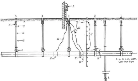
Vertical Movement Gages
Rods were supported on the pipe and extended to the ground surface through sleeves, with clearance to per-mit free movement. A removable cover at the toD of the sleeves and
B A R A C O S . H U R S T . L E G G E T J o u r . A l A W A
showed that, locally, this depth was relatively free of seasonal soil ments. Details of these pipe move-ment gages are shown in Fig. 2.
In Installation A, the gages were placed on four consecutive lengths of pipe. In Installations B and C, the gages were placed on 5 consecutive lengths. A further improvement in these two installations was a deeP
4 - i n . o r 6 - i n D i a m . Cast-lron Pipe
fi
w"
Fig. 2. Schematic Representation of Typical Test Installation
J-therrnocouples; K-tkerynocouple temperoture weII; and L-deep benckmark 'in undisturbed soiL.
grease packings at the top and bottom prevented water from entering. A similar rod was supported on undis-turbed soil at a depth of 12 ft, and this was used as a reference datum for checking elevations at the top of the
rods. 'Ihe lZ-ft depth was selected on
the basis of the universitv tests which
bench mark supported at a dePth of about 30 ft, although a much shallower depth would have been satisfactory. This bench mark was placed to deter-mine whether such a 30-ft deep rod could be used to establish a satisfactory bench mark in Winnipeg soils. It had been specially developed by the
Dec. 1955 E N V I R O N l \ T E N T A L DFFECTS ON PIPE
1203
Building Research Div. for deterrnin-ing an elevation datum not subject to vertical soil movement, an essential factor in the division's soil and founda-tion studies. Readings on the bench mark and the vertical movement gages were carefully taken with an engineer's level.
Electric Strain Gages
The use of electric strain gages for measuring strains in buried pipe pre-sents many difficulties. Considerable time was spent in devising methods of waterproofing the gages, which are ex-tremely sensitive to moisture. For Installation A, the gages were water-proofed after being attached to the pipe, by using a plastic tape covering sealed with a self-vulcanizing syn-thetic rubber compound. The electri-cal leads were placed in a plastic hose. After the pipe was installed, gradual deterioration in the gages was indi-cated by the decrease in electrical re-sistance between the gage and pipe, showing that moisture had entered there. In Installations B and C, the gages on the pipe were covered by a thin copper sleeve which was packed with grease. This proved a very ef-fective means of moisture-proofing. Compensating gages on nonstressed specimens of pipe, which are a neces-sary part of the instrumentation, were placed in separate water-tight contain-ers and buried adjacent to the pipe. Bakelite-type electric strain gages were used in preference to paper-backed gages because of their supeqior long-period performance. For measuring longitudinal strains, the gages were placed all around the pipe, parallel to the longitudinal axis, at mid-length of a pipe section. A thermosetting ce-ment was used to attach the gages to fhe pipe, which had been lightly
nra-chined to expose a clean metal surface. On Installation A, the gages were used on one length of pipe only. In Instal-lations B and C, the gages were placed on two adjacent lengths of pipe. Ini-tial strain readings were taken after the pipe was placed, but before back-filling. The readings were taken by connecting the necessary instruments to the terminal box, which was equipped with a double-contact rotary selective switch.
Thermocouples
Copper-constantan thermocouples, for measuring soil and water tempera-tures, were installed at various depths adjacent to the buried pipe. In the pipe in Installation C, they were placed in a temperature well. The electrical leads were taken to the terminal box and connected to a double-contact rotary selector switch. A potentiome-ter was used for taking the readings. SoiI Tests
Moisture content samples and bulk samples of soils underlying the pipe and of backfill were obtained. Plas-tic and liquid limit tests were per-formed, and they confirmed the high mechanical activity of the soils and their susceptibility to shrinking and swelling with moisture variations. These values were particularly high for the soils supporting the pipe at the bottom of the trench. Records were taken during the laying of the pipe and at frequent intervals thereafter.
An overall picture of a typical instal-lation is shown in Fig. 2.
Test Results
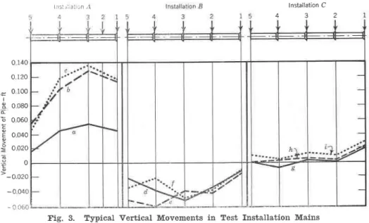
The vertical movement gages proved extrernely informative. Some typical ranges of movement are shown in Fig. 3 Test Installation I showed that the
1204
pipe can move upward as much as 2 in. when "trench and tunnel" methods of excavation are used. The large up-lvard movement here can be attributed to poor backfilling. This results in improper compaction, allowing surface waters to percolate into the trench and causing the supporting clays to sweli. The backfill, because of its loose con-dition, does not effectively oppose the
l i t 5 i r i r a L r r n , l
B A R A C O S , H U R S T , L E G G E T t o u r . A W W A the tightened joints. Such movement in corrosion-weakened pipe could well cause flexural or joint failure. The ntagnitude of the movement is particu-larly significant when it is realized that for the entile time that the test pipes were installed, generally wet climatic conditions prevaiied. There were no dry soil .oiditio.rr which would have pern-ritted soil shrinking.
lnstallation C 4 3 2 0 140 o 120 0 100 0 080 0 060 0 040 0 020 0 -0.020 I c E -0 040 - c 0 5 0
Ir,tstallation L, installed Dec. 19, 1953, zuas of 6-in. cast-iron pipe. Instahlation B, in-stallcd, Ar,t,g.24, 1954, and Installation C, installed Noa. 18,1954, were of 4-in. cast-iron pifc. Dates of tke tests for wh,ick data are strt'own zuere as folLozus: a-Mar.37, 1 9 5 4 ; b - O c t . 2 0 , 1 9 5 4 ; c - M a r . 1 2 , 1 9 5 5 ; d - S e p . 1 , 1 9 5 4 ; e - O c t . 2 0 , 1 9 5 4 ; f - M a r . 12, 1955; g-lan.2, 1955; h-Feb. 14,1955; i-Apr. 30, 1955. Datum is tke
elezta-tion of pipe on date of installaelezta-tion.
upward movement. Winnipeg uses It was found that the electric strain this "trench and tunnel" method for gages could be successfully water-laying pipe under paved streets or for proofed. The readings showed that winter work when excavation in lrozen the pipe was subject to axial as well ground is extremeiy expensive. as flexural stresses, and that bending
More irnportant, however, is the dif- could take place both in a vertical and ferential movement of the buried pipe horizontal direction. Because consid-exhibited by all three test installations. erable study is still required in success-This amounted to as much as f in. and fully developing the electric strain sometimes caused * d.g. of rotation at gages for underground work, only
Dec. 1955 E N V I R O N M E N T A L E F F E C T S O N P I P E
1 2 0 5
qualitative results can be given at this time. It is interesting to note that high strains developed in the pipe on backfilling and that these strains have remained high.
For Installation A, the thermo-couple showed a maximum frost pene-tration of 8 ft during the winter of 1953-54. This unusually deep pene-tration was caused by the frozen condi-tion of the backfill when it was placed in the trenches. During the winter of 1954-55, frost penetration reached a depth of 5 ft in mid-March. The coldest ground temperature reached, other than at the surface, was 20oF at a l-ft depth. At 8 ft, the tempera-ture varied between 35" and 45oF. For Installation C, it was found that, from the end o{ October to the begin-ning of March, the ground at pipe depth u'as approximately 1-3'F warmer than the pipe. The coldest water tem-perature reached was 34oF and the coldest ground temperature at this depth was 35oF. The test pipes have not been installed for a suffrcient length of time to permit a comparison of sum-mer ground and pipe temperatures. Based on readings made to date, how-ever, it is possible that the water is at least 9oF warmer than the ground.
This report represents only a con-densation of the results obtained. Conclusions
It will be clear that this paper is essentially a report of progress made on a long-term, extensive research project, which is still under way. De-tailed findings and conclusive results will be reported in due course in ap-propriate research papers, The results obtained to date, however, show that the investigation has implications that go far beyond the purely local prob-lem. On the basis of what the project
has already revealed, both from a study of the cumulative experience of the water works branch of Winnipeg's Eng. Dept. and from the initial infor-mation gained in the test installations, the following conclusions can be made: 1. Water main breaks occurring in the Winnipeg system have constituted a problem throughout the years that is of such magnitude that it has necessi-tated detailed analysis and regular review.
2. The corrosive character of the local soils in the presence of moisture is undoubtedly a principal factor in the failure of cast-iron mains. But other considerations, such as the breaks oc-curring in steam-cured asbestos-cement pipe, which has high corrosion resist-ance, and the seasonal recurrence of a peak in the nurnber of failures, indi-cate that the physical environment of the pipe is also partly responsible for the failures. Cumulative experience with Winnipeg soils indicates that the associated factor is differential soil movement.
3. Such differential soil movements can result when pipe trenches are exca-vated in clay soils which are suscepti-ble to swelling or shrinking with changes in the moisture content, a dif-ficulty which is inevitably traced back to the backfilling operation.
4. The initial readings show that, because of differential soil movements, the pipes move to such an extent after installation that appreciable bending stresses ffiay be induced. These stresses are believed to be of such mag-nitude that they could cause the failure of corrosion-weakened pipe.
5. The previously observed inter-action of soil and pipes confirms most emphatically the long recognized im-portance of properly backfilling pipe trenches and of laying pipe on well
1206
prepared soil beds without the use of solid blocking.
6. Even when excellent workmen are involved, field observations confirm the difficulty of achieving good laying practice without almost continual in-spection of every pipe-laying operation.
7. Although the Winnipeg soil con-ditions are unusual, they are by no means unique. The experience re-corded in this paper, then, is probably applicable to many other areas. References
1. Hunsr, W. D. The Use of Asbestos-Cement Pressure Pipe to Combat Soil Corrosion in Winnipeg. Wtr. & Wtr. Ens. (Br.), Vol. I (Mar. 1951). 2. Bunnrs, N. S. Maintenance and
Opera-tion Problems of Winnipeg Water Works System. Wtr. & Sezu. Wks., 8 6 : 2 5 (S e p . 1 9 4 8 ) .
3. Surer-ev, J. W., a Srrrrn, W. Nersox. Self Corrosion of Cast Iron and Other Metals in Alkaline Soils. l. Eno. Inst. Canada,4:527 (Oct. l92l). 4. Surrn, W. Nnr-sor. Self Corrosion,
Not Stray Current Electrolysis at Sel-kirk, Manitoba. J. Eng. Inst. Canacla, 4:413 (Jut. 192r).
5. Report on Transite Pipe Experience-Water Works and Sewerage Branch, City Eng. Dept., Winnipeg (Feb. 1 9 5 1 ) .
BARACOS. HURST. LEGGET
7
Jour. AI4/ WA
LrccEr, R. F. Government Sponsored Research-A Canadian View. Tech-nical Paper No. 21, Div. of Building Research, National Research Council of Canada, Ottawa (1953).
SurrronraNo, Hucn B. A Study of Vi-bratiqns Produced in Structures by Heavy Vehicles. Research Paper No. 3, Div. of Building Research, National Research Council of Canada, Ottawa
( D e c . 1 9 5 0 ) .
Rurnrnrono, D. H., a Banecos, A Damage to lfouses, Red River Valley Flood, 1950. Technical Report No. 9, Div. of Building Research, National Research Council of Canada, Ottawa
( M a r . 1 9 5 3 ) .
Vnnmox, W. J. Principles of Corrosion in Corrosion Preaention and Control. London (1954).
MecmNern, A. E. Report of the Win-nipeg Branch of the Engineering In-stitute of Canada Committee on Foun-dations. J. Eng. Inst. Canada 20:827
( N o v . 1 9 3 7 ) .
Benecos, A., c ManeNrz, O. Vertical Ground Movements. In Proceed.i'ngs of tke Sirth Canadian Soi.l Mechani,cs Conlerence, Dec. 1952. Technical Memorandum No. 36, Associate Com-mittee on Snow and Soil Mechanics, National Research Council of Canada, Ottawa.
American Recommended Practice Man-ual for the Computation of Strength and Thickness of Cast Iron
Pipe-ASA 421.1 (AWWA C101). Am.
Wtr. Wks. Assn., New York
( 1939) .
10.