DOI 10.1140/epja/i2005-10319-4
P
HYSICAL
J
OURNAL
A
Improved radiative corrections for
(e,
e
0
p) experiments: Beyond
the peaking approximation and implications of the soft-photon
approximation
F. Weissbacha, K. Hencken, D. Rohe, I. Sick, and D. Trautmann
Departement f¨ur Physik und Astronomie, Universit¨at Basel, CH-4056 Basel, Switzerland Received: 10 November 2005 / Revised: 31 October 2006 /
Published online: 21 December 2006 – c° Societ`a Italiana di Fisica / Springer-Verlag 2006 Communicated by Th. Walcher
Abstract. Analyzing (e, e0p) experimental data involves corrections for radiative effects which change the
interaction kinematics and which have to be carefully considered in order to obtain the desired accuracy. Missing momentum and energy due to bremsstrahlung have so far often been incorporated into the simula-tions and the experimental analyses using the peaking approximation. It assumes that all bremsstrahlung is emitted in the direction of the radiating particle. In this article we introduce a full angular Monte Carlo simulation method which overcomes this approximation. As a test, the angular distribution of the brems-strahlung photons is reconstructed from H(e, e0p) data. Its width is found to be underestimated by the
peaking approximation and described much better by the approach developed in this work. The impact of the soft-photon approximation on the photon angular distribution is found to be minor as compared to the impact of the peaking approximation.
PACS. 13.40.-f Electromagnetic processes and properties – 14.20.Dh Protons and neutrons – 21.60.-n Nuclear structure models and methods – 29.85.+c Computer data analysis
1 Introduction
Much of our knowledge about nuclear structure, e.g. the momentum distribution of nucleons in the nucleus, is based on (e, e0
p) experiments. Currently several such ex-periments are carried out at the Thomas Jefferson Na-tional Accelerator Facility (TJNAF) in Newport News and at the Mainz Microtron (MAMI) in Mainz, taking data at high initial momenta and removal energies in particular. These experiments are aiming at a deeper understanding e.g.of short-range correlations in nuclei and their results are used to check important ingredients of modern many-body theories.
In (e, e0
p) experiments all particles involved are subject to the emission of bremsstrahlung. On the one hand, con-sideration of bremsstrahlung contributions is necessary to renormalise the higher-order QED amplitudes. In the sec-ond order, divergences from the bremsstrahlung diagrams cancel with those resulting from vertex corrections as has already been shown by Schwinger in 1949 [1] for elec-trons scattering off an external potential and for electron-proton scattering by Tsai in 1961 [2], including divergent contributions from the two-photon exchange (TPE) di-agrams. On the other hand, bremsstrahlung modifies the cross-section integrated over finite intervals of energy loss.
a e-mail: [email protected]
Bremsstrahlung photons can be so energetic that they influence the electron’s and the proton’s three-momenta considerably; thereby also the momentum transfer be-tween the two particles is changed. This phenomenon has been studied in a number of papers [3–19] both for inclu-sive and excluinclu-sive electron scattering experiments.
Radiative corrections to (e, e0
p) scattering, including bremsstrahlung, vertex corrections, and vacuum polariza-tion (see Feynman diagrams in fig. 1) can in principle be calculated exactly in (pure) QED and to a good accuracy also including hadronic loops. But for practical purposes several approximations are usually employed when cor-recting experimental data for radiative effects [20].
One of them is the soft-photon approximation (SPA). It makes use of the fact that in the limit where ω0→ 0 a
bremsstrahlung photon with energy ω0has neither a
kine-matic effect on the scattering process nor an effect on the QED propagators and amplitudes. Then the SPA section factorizes into the elastic first-order Born cross-section times the probability for emitting a bremsstrah-lung photon with vanishing energy. Analysis procedures for (e, e0
p) experiments make use of the SPA [20] because it simplifies the calculation of multi-photon bremsstrah-lung considerably [18].
Multi-photon bremsstrahlung has to be included into electron scattering data analysis [18, 21] in order to both
impose the physical asymptotic behaviour on the cross-section and to achieve percent level accuracy. While these higher-order bremsstrahlung contributions are, in princi-ple, also computable exactly in QED, their evaluation has to be truncated for practical purposes. The SPA is con-venient, because it allows for straightforward inclusion of multi-photon bremsstrahlung into data analysis to all or-ders [18], as we will see in sect. 2.
The SPA is only valid in the limit of vanishing brems-strahlung photon energy; however in radiative correction procedures the SPA is applied to photons with energies of up to several hundred MeV. The question arises up to which photon energies the SPA can be considered a good approximation. This paper will not answer that question albeit we will present indications that one of the physical observables (the missing energy) does exhibit sensitivity to shortcomings of the SPA.
(e, e0
p) data analyses do not employ the “pure” SPA (called pSPA in the remainder of this paper) described above. Usually, the SPA is modified such that i) it takes into account kinematic effects due to emission of finite-energy bremsstrahlung photons, and ii) it evaluates the form factors at a modified value of the momentum trans-fer of the virtual exchanged photon, q. We will retrans-fer to this “modified” SPA as the mSPA. In mSPA each particle emitting bremsstrahlung is put onto the mass shell.
The SPA neglects the proton structure at the brems-strahlung vertex. But, as has been shown in ref. [15], for the kinematic settings considered in the present paper, the influence of the proton structure at the bremsstrah-lung vertex is not important.
The other approximation used in radiative correction procedures is the peaking approximation (PA). Most of the bremsstrahlung photons from the electron are emit-ted either in the direction of the incoming (e) or outgoing electron (e0
) and one can observe two radiation peaks at the respective angles. The proton (p0
) bremsstrahlung is much less peaked. At very high-momentum transfers one can see a bump (rather than a peak) in its direction, too (see fig. 2). The PA, first proposed for (e, e0
) experiments by L. I. Schiff [3] in 1952, makes use of this observation by assuming that all radiation goes either in the direction of the incoming electron, or the scattered electron. With the advent of coincidence experiments the PA was extended to (e, e0
p) data [18], assuming that the proton bremsstrah-lung was peaked, too. The PA projects the non-peaked contributions to the bremsstrahlung photon angular dis-tribution onto the three peaks. Especially between the two radiation peaks due to electron bremsstrahlung the dis-crepancy with data becomes large (see fig. 3), limiting the accuracy of (e, e0
p) data analyses [5, 6].
The purpose of this paper is to remove the PA from (e, e0
p) data analyses. The need for the removal of the PA became evident when looking at the bremsstrah-lung photon angular distribution in H(e, e0
p) experiments (see fig. 3). In this paper, we introduce a full angu-lar Monte Carlo (FAMC) method which generates multi-photon bremsstrahlung events according to the mSPA photon angular distribution. A similar FAMC code for
(e, e0
p) experiments has been described in ref. [19]. But it has not been inserted into any data analysis codes nor does it handle multi-photon bremsstrahlung. In connec-tion with virtual Compton scattering, ref. [22] introduces a numerical calculation of radiative corrections beyond the PA, but it considers single-photon emission only, whereas multi-photon contributions are large. To check our re-sults against experimental data we use the SIMC analysis code [20] for Hall C at TJNAF and E97-006 experimental data [23].
While we do not want to anticipate the results from sect. 5 at this stage, we do state here on a preliminary basis that removing the PA can only be a first step on the way to an improved calculation not relying on the SPA. For beam energies envisaged for the TJNAF upgrade, a cal-culation going beyond the SPA might become necessary, albeit an exact multi-photon bremsstrahlung calculation is impracticable.
This paper is organized as follows: In sect. 2 we in-troduce the bremsstrahlung cross-section including multi-photon bremsstrahlung, discussing the QED divergences. Our calculation partially follows ref. [18], as the result-ing equations form the basis for our FAMC calculation. In sect. 3 we extend this approach to a FAMC simula-tion allowing for any number of bremsstrahlung photons emitted into the full solid angle according to the full an-gular distribution. In sect. 4 we compare the results of the FAMC simulation to the PA using the SIMC code, and in sect. 5 we discuss scope and validity of the SPA, com-paring it to the exact QED calculation for single-photon bremsstrahlung from the electron (which will be called “1γ calculation”).
The speed of light has been set to c = 1 throughout the paper.
2 Bremsstrahlung cross-section
In order to obtain the electron-proton cross-section to or-der α2 including bremsstrahlung with energy less than
ωmax,
dσ dΩe
(ω0< ωmax) , (1)
where ω0is the bremsstrahlung photon energy, the
ampli-tudes depicted in fig. 1 are considered. The four brems-strahlung diagrams contributing to Mbrems are divergent
in the limit of vanishing bremsstrahlung photon energy ω0. These divergences cancel the ones both from the TPE
diagrams1 and the vertex corrections [1]. The TPE
dia-grams are special cases. While consideration of their diver-gent pieces is necessary in order to remove all divergences from the scattering amplitudes, their finite contributions are known to be negligible in electron scattering exper-iments [24–27] unless a very small L(T )-contribution is determined via an LT -separation. Mo and Tsai calculated
1 The divergences from the TPE diagrams cancel with the
one from the electron-proton bremsstrahlung interference term which appears after squaring the full scattering amplitude.
Miradc ∼ + +
+ + +
+ + + +
Mbrems ∼ +
+ +
Fig. 1. The Feynman diagrams contributing to the internal radiative corrections together with the Born amplitude (top) and the diagrams contributing to the bremsstrahlung ampli-tude (below). The label “iradc” is the shorthand for internal radiative corrections and “brems” stands for bremsstrahlung.
Table 1.The kinematic setting used in fig. 2.
Q2 15 GeV2 k0 21.00 GeV |k0| 13.00 GeV |p0| 8.882 GeV θe 13.5◦ θp −19.9◦
the TPE diagrams approximately using only the nucleon intermediate state in the limit where one of the two ex-changed photons has zero momentum. They applied this approximation both in the numerator and in the denom-inator of the fermion propagator [8]. Maximon and Tjon improved this calculation by removing this approximation from the denominator of the fermion propagator [12, 15]. Blunden, Melnitchouk, and Tjon did the calculation using the full propagator [28, 29]. According to ref. [28] a model-dependent calculation of the influence of the TPE yields effects of the order of 1–2% for the kinematic settings con-sidered in the present paper. Most (e, e0
p) analysis codes follow the calculation by Mo and Tsai [18, 20].
The SPA allows us to approximate the four brems-strahlung diagrams by a product of the Born amplitude times a correction factor. In SPA, e.g., the amplitude for incident electron bremsstrahlung can be approximated as
Mei= eM(1)ep µ −ε · k ω · k ¶ (ω0→ 0) . (2) This amplitude corresponds to the second Feynman dia-gram of Mbrems in fig. 1. M(1)ep is the first-order Born
amplitude, ω = ω0(1, 1, Ω
γ) the photon four-momentum,
ε is the bremsstrahlung photon helicity vector, and k = (k0, k) the incident electron’s momentum. The
four-momentum of the scattered electron will be denoted as k0
= (k00, k0
), and for the proton we will use p = (p0, p)
(incoming) and p0 = (p00, p0 ) (outgoing). −10 0 10 20 −1 −0.5 0 0.5 1 −80 −40 0 40 80
θ [degrees]
10−10 10−5 100 105yield
2
1
3
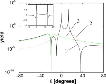
γFig. 2. (Colour on-line) Single-photon angular distribution of bremsstrahlung using the SPA. The full line (1) (black) shows the full angular distribution A(Ωγ) from eq. (4), the dotted
line (2) (red) considers pure electron contributions (ee) only, the dashed line (3) (green) shows the pure proton contribution (pp). The interference term is partially negative and is shown in the inset graph. It is small compared to the other contributions. The momentum transfer is Q2= 15 GeV2, the entire kinematic
setting can be found in table 1. The dip for the proton is due to the fact that a massive particle cannot radiate a photon in forward direction. The same is true for electrons but the width of the respective dip is extremely narrow [18, 22].
Evaluating the Feynman diagrams in the SPA one can show [18] that the cross-section for the single-photon bremsstrahlung is dσ dΩedΩγdω0 =dσ (1) dΩe A(Ωγ) ω0 , (3)
where Ωγ denotes the bremsstrahlung photon angles
and dσ(1)/dΩ
e is the Born section. In the
cross-section (3) the dependences on photon energy and photon angle factorize and
A(Ωγ) ≡ αω02 4π2 µ − k 0 ω · k0 + p0 ω · p0 + k ω · k − p ω · p ¶2 (4) does not depend on the photon energy.
Integrating over photon angles and energies the total cross-section for emitting a photon with energy smaller than ωmax can be written as
dσ dΩe (ω0< ω max) = dσ(1) dΩe
[1 − δbrems(ωmax) − δiradc] . (5)
The necessary integration techniques can be found in [30], the remaining calculations are explicitly carried out in ref. [18]. The contributions from vertex correction and vac-uum polarization (the internal radiative corrections) are included in δiradc≡ 2α " − 3 4πlog µ Q2 m2 ¶ + 1 π− X i δivp(Q2) # , (6)
θ
γ(degrees)
0
500
1000
1500
−50
0
50
yield
4
Fig. 3. (Colour on-line) Bremsstrahlung angular distribution for the H(e, e0p) reaction at the kinematics given in table 2.
The solid curve (3) (black) shows the measured experimental angular distribution of bremsstrahlung. The experimental pho-ton angle θγ is reconstructed from the missing momentum
ac-cording to eq. (22). The dotted line (1) (green) and the dashed line (2) (red) correspond to a Monte Carlo simulation based on the PA and take into account detector resolution. The red line takes into account the emission of bremsstrahlung from e, e0,
and p0, whereas the green line only allows for bremsstrahlung
emitted solely from either e, e0, or p0. The solid line (4) (blue)
in the vicinity of the proton direction simulates a deficiency of the apparatus (proton punch-through effects). The PA over-estimates the two photon peaks in the two electron directions (e and e0) and it underestimates the bremsstrahlung between
these two peaks as well as between the peaks in incident elec-tron direction e and in proton direction p0 and the radiation
on the large-angle tail of the e0 peak. Both data and
simula-tions account for luminosities and detector efficiencies, and no arbitrary normalization factor is employed.
Table 2. The kinematic setting at which the standard radia-tive corrections and the FAMC simulation are compared to data. Q2 2 GeV2 k0 3.120 GeV |k0| 2.050 GeV |p0| 1.700 GeV θe 32.5◦ θp −38.5◦
where the vacuum polarization contribution is δivp(Q2) ≡ 1 3π · −5 3 + log µ Q2 m2 i ¶¸ (7) in the ultra-relativistic (UR) limit. This expression does not only contain electron-positron loops but also heavier lepton and light quark–anti-quark loops, midenoting their
respective masses. The bremsstrahlung is contained in δbrems(ωmax) ≡ α π ½ logµ |k||k 0 | ω2 max ¶ · logµ Q 2 m2 ¶ − 1 ¸ + logµ p 0p00 ω2 max ¶ · logµ Q 2 M2 ¶ − 1 ¸ +1 2log 2µ p 00 M ¶ + logµ p 0p00 ω2 max ¶ × logµ |k| |k0| ¶ + logµ |k||k 0 | ω2 max ¶ logµ |k| |k0| ¶ +1 2log µ |k||k0 | M2 ¶ logµ |k| |k0| ¶¾ , (8) also given in the UR limit. The single-photon cross-section (5) is still divergent in the limit of vanishing ωmax. By taking into account higher-order bremsstrahlung
(multi-photon bremsstrahlung) this divergence is rendered finite [4, 21] and, at the same time, experimental accuracy is enhanced. It was first shown in ref. [4] that in fact all orders of bremsstrahlung contributions can be considered by just exponentiating the bremsstrahlung term in the cross-section (5), yielding dσ dΩe (ω0 i< ωmax) = dσ(1) dΩe
exp[−δbrems(ωmax)][1−δiradc].
(9) The index i indicates that an infinite number of photons, each with an energy less than ωmax, is emitted.
Exponen-tiating δbremsleads to the correct asymptotic behaviour of
the cross-section (5) as ωmax→ 0.
We now consider the cross-section for emitting n pho-tons with an energy larger than an artifically introduced energy cut-off parameter Emintogether with multi-photon
emission of photons with individual energies less than the energy cut-off Emin[18],
dσ(n, Emin)
dΩedω01dΩ1. . . dω0ndΩn
=dσ
(1)
dΩe
exp[−δbrems(Emin)]
×(1 − δiradc) ×1 n! A(Ω1) ω0 1 . . .A(Ωn) ω0 n ×θ(ω0
1−Emin) . . . θ(ω0n−Emin) .
(10) In order to integrate this cross-section, let us introduce an “acceptance function” χn
A(Ωe, ω01, Ω1, . . . , ω0n, Ωn),
de-pending on the kinematical variables of the scattered elec-tron and the n photons with energies larger than Emin.
Multiplying eq. (10) with χn
A, integrating over all photon
energies up to an upper boundary Emax > Emin, chosen
large enough to include all photons, where χn
Ais non-zero,
we obtain the cross-section dσ
dΩe
[χA] =
dσ(1)
dΩe
exp[−δbrems(Emin)](1 − δiradc)
× ∞ X n=0 1 n! n Y i=1 Z Emax Emin dω0 i ω0 i Z dΩiA(Ωi)χnA. (11)
This way, cross-sections with very general restrictions on, e.g., the energy loss by the photons can be calculated. The acceptance function χA≤ 1 is the probability for the
event to be counted in dΩdσe[χA].
Proceeding towards a FAMC calculation we evaluate the cross-section (11) using Monte Carlo integration tech-niques. In order to rewrite the integral into the standard Monte Carlo sum over randomly selected values, we need to rewrite the cross-section in terms of probability density functions (PDFs) for the photon variables. The PDFs are then used to generate the random values.
As we want to keep the shape of χn
Ageneral, it is kept
in the expression for the cross-section and is implemented in the Monte Carlo generator by a standard rejection al-gorithm. The integral is easily converted into the shape demanded by the Monte Carlo generation by multiplying with its value for χn
A= 1 and normalizing it.
The value of the angular integral (without any χA)
λ ≡ Z
dΩγA(Ωγ) (12)
is independent of the photon energy and A(Ωγ) is the
an-gular distribution from eq. (4) which is plotted in fig. 2 (for φ = 0) for a sample kinematic configuration (see ta-ble 1). The integrals over the ω0i can be trivially solved
and the product over i just yields a power of n.
Re-writing the cross-section in terms of the PDFs for the bremsstrahlung photon energies ω0
i, the angular
dis-tribution and their multiplicity n, leads to dσ
dΩe[χA] =
dσ(1)
dΩe exp[−δbrems(Emin)](1 − δiradc)
×eλlog ³Emax Emin ´ ∞ X n=0 PDF(n) × n Y i=1 Z dω0 i PDF(ωi0) × Z dΩiPDF(Ωi)χnA, (13) where PDF(ω0i) ≡ 1 ω0 i log ³ Emax Emin ´ (14)
is the PDF for the photon energies ω0 i,
PDF(Ωi) ≡
A(Ωi)
λ (15)
is the one for the angular distribution and PDF(n) ≡ 1 n! · λ logµ Emax Emin ¶¸n e−λlog ³Emax Emin ´ (16) is the PDF for the photon multiplicity, which is just a Poisson distribution. The total cross-section (13) does not depend on Eminbecause δbrems(Emin) and λ are such that
Emincancels, as has been shown by R. Ent et al.in ref. [18].
In the same reference [18] it is shown that the cross-section for emitting several photons each with energy less than a cut-off Emin,
dσ dΩe
(ω0
i < Emin) , (17)
is, within a correction of order α2, the same for the case
where instead of the individual photon energies the sum of the energies of all bremsstrahlung photons is smaller than the cut-off,
dσ dΩe à X i ωi0< Emin ! = dσ dΩe (ωi0< Emin)[1 + O(α2)] . (18) Therefore the cross-section (13), within an order α2
cor-rection, can be regarded as the cross-section for multi-photon emission below a small cut-off Emin, the sum of
these soft photons being Emin, along with the emission
of n hard photons with energies above Emin and below
Emax. The dependence on Emincancels [18]. For practical
purposes, in (e, e0
p) data analyses, Emin is often set to a
value below the detector resolution, and the bremsstrah-lung photons below that small cut-off are not considered in the analyses, as even their sum will not affect the mea-sured result: eq. (18) ensures that neglect of these photons only amounts to missing energies below the detector reso-lution within an order α2correction. For the value of E
max
we can always use the total energy of the incoming elec-tron, as a reasonable acceptance function disallows events, where the photons have together more energy than the to-tal energy available.
Starting with the cross-section in (10) we can also obtain differential sections. For example, the cross-section differential in the total energy of all emitted brems-strahlung photons Etot, dΩedσdEtot, is calculated by choosing
χn
A= δ(
Pn
i=1ω0i − Etot0 ), yielding
dσ dΩedEtot
= dσ
(1)
dΩe
exp[−δbrems(Emin)](1 − δiradc)
×eλlog ³Emax Emin ´ ∞ X n=0 PDF(n) × n Y i=1 Z dωi0PDF(ωi0) ×δ Ã n X i=1 ω0 i − Etot ! , (19)
where we have made use of the fact that in this case the in-tegration over the angular variables can be done trivially. In the Monte Carlo simulation events are generated according to the PDFs (14), (15), and (16) and the results are binned in the vicinity of
X
i
ω0i ≈ Etot. (20)
As discussed above, n, Ωi, and ω0i have to be generated
has been used in (e, e0
p) data analysis codes (in connection with the PA) and is well established [20], an (e, e0
p) data analysis code using a multi-photon FAMC simulation is novel. In the next section we will describe how the photon angular distribution (4) is generated.
3 Full angular Monte Carlo simulation
For H(e, e0
p) data the PA exhibits its limitations espe-cially in the middle between the two radiation peaks in e and e0
directions2 where it underestimates the strength
of the bremsstrahlung. The same is true for the region between the peaks in e and p0
directions. In this section we introduce a FAMC simulation for multi-photon brems-strahlung following the SPA distribution in eq. (4) in order to see whether this cures the problem. In order to gener-ate Monte Carlo events according to the angular distribu-tion (4) we need a set of invertible envelope curves ˆAi(Ωγ)
which limit A(Ωγ) from above,
X
i
ˆ
Ai(Ωγ) ≥ A(Ωγ) (21)
for all photon angles Ωγ. In order to obtain the exact
distribution (4) from the envelope curves we then employ a standard rejection algorithm.
The envelope curve chosen by us consists of four terms. In order to be able to apply the mSPA we need to assign each bremsstrahlung photon to one of the particles. Three of the four contributions to the envelope curve can unam-biguously be assigned to bremsstrahlung from the incom-ing and outgoincom-ing electron and the outgoincom-ing proton. The fourth envelope term takes up the remaining part. It is an angle-independent distribution at first but shaped by the rejection algorithm into a contribution which is given by ee interference. There are several “coin toss” methods to choose whether an event created from the interference term is assigned to the incoming or the outgoing elec-tron or to both. We employed three different ways of deal-ing with the interference term, leaddeal-ing to slightly differ-ent results. Together with the Monte Carlo photon energy generation (14) and with the photon multiplicity gener-ation (16) each of these three ways of dealing with the interference term constitutes a Monte Carlo event gener-ation method for the interference term.
1. The interference term (being essentially a function of the photon angle θγ) is split into two parts, the “left
part” consisting of events with angles closer to θe and
the “right part” with angles closer to zero. Events closer to the incoming electron direction (“right”) were counted for the incoming electron whereas events closer to the outgoing electron (“left”) direction were counted for the latter one.
2. In addition to method (1) the energy loss generated using (14) is randomly split between incident and scat-tered electron.
2 Only for H(e, e0p) the missing-momentum vector and thus
its direction is solely due to emission of bremsstrahlung pho-tons below the pion threshold.
θ
γ(degrees)
0
500
1000
1500
−50
0
50
yield
Fig. 4. (Colour on-line) Angular distribution of bremsstrah-lung photons. The dotted line (1) (green) and the dashed line (red) (2) represent the simulations using the PA (the dif-ference between the two curves is explained in the caption to fig. 3), and the solid line (3) (black) shows the measured (recon-structed) experimental angular distribution, as in fig. 3. The dot-dashed curve (4) (blue) represents our FAMC simulation (not using the PA; employing method 3 described in the text; see fig. 6). The peaks in e and in e0direction generated by the
FAMC simulation (4) are broader than the ones from the PA, (1) and (2), and reproduce the data more accurately, especially between the peaks in e and e0 direction. The height of the e0
peak is slightly underestimated by the FAMC simulation (4), as well as the large-angle tail beyond the e0 peak. For details
concerning the proton direction see fig. 5. As in fig. 3 both data and simlations are corrected for luminosities and detector effi-ciencies, and no arbitrary normalization was introduced.
3. The emitted photon is randomly assigned to either the incoming or the outgoing electron.
For the final comparison between the standard brems-strahlung treatment (using PA) and our FAMC simulation we used the third method as it fitted the reconstructed photon distribution most accurately, as we will see in the next section.
Once a bremsstrahlung event has been assigned either to the incident electron, the scattered electron or to the struck proton, in mSPA the four-momenta, k, k0
, and p0 are replaced by k → k − ω, k0 → k0 − ω, or by p0 → p0 − ω, respectively, and the momentum transfer q2 is adjusted
and inserted into the form factors. ω is the four-vector of the bremsstrahlung photon.
To check the results produced with our Monte Carlo routine against experimental data we implemented it into the SIMC code [20] developed for Hall C at TJNAF. We used a modified version which was used for the E97-006 (e, e0
p) experiment [23]. Computation times with and without the new FAMC simulation were similar.
0
50
100
150
20
40
60
yield
(degrees)
θ
γFig. 5.(Colour on-line) Angular distributions of bremsstrah-lung photons. This figure is a cutout of fig. 4, focussing on the region around the proton direction. On the small-angle tail of the proton peak the FAMC simulation (4) does not en-tirely overcome the gap between simulation and data. However, the region around the proton direction is obscured by punch-throughs.
4 Results
To test our approach we chose H(e, e0
p) kinematics with a beam energy of 3.12 GeV. We usually generated 600000 successful Monte Carlo events per run to compare PA and FAMC simulation. Figures 4–10 show results for the kine-matic setting given in table 2.
The photon angles shown in figs. 3 and 4 are obtained according to the prescription
θγ = arctan µp my pmz ¶ , (22)
where pmy and pmz are the missing momenta in y- and
in z-direction, respectively. Our co-ordinate system is the one used by SIMC, described in [31].
As pointed out in the introduction, the PA underesti-mates non-peaked radiation especially between the radia-tion peaks in the direcradia-tions of the incident and the scat-tered electron [5, 6]. One can see in fig. 4 that the photon angular distribution broadens when employing the FAMC simulation. The gap between the experimentally deter-mined bremsstrahlung distribution and PA (see fig. 3) be-tween the two radiation peaks in e and e0
direction is filled. When calculated with our FAMC method, also the peak in the proton direction fits the reconstructed brems-strahlung data (see fig. 5). However, this has to be put into perspective as the proton bremsstrahlung is obscured by a detector-related artefact (punch-through effects) such that one cannot make a clear statement on the accuracy here. For the kinematic setting shown in table 2 the ee inter-ference term discussed in the previous section was treated with method (3). This led to the best agreement with
0
500
1000
1500
−50
0
50
(degrees) θ yield γFig. 6. (Colour on-line) Photon angular distribution for the three different treatments of the interference term (see sect. 3). Method (1) is represented by the dashed line (red) and it co-incides with method (2) (not shown). The dotted line (blue) represents method (3), the solid line (black, marked with a square) shows the data. Method (3) is found to reproduce the data most accurately and is hence used for the FAMC simula-tion (4) in fig. 4.
1
10
10
210
310
40
0.2
0.4
0.6
missing energy [GeV]
yield
Fig. 7. (Colour on-line) Logarithmic plot of missing-energy distribution. The dotted line (black) was obtained using the PA, the solid line (red) shows the results obtained with the FAMC simulation. The total radiated energy simulated for the latter case is only about 0.3% smaller than the one from the PA. Reasons for this deviation are given at the end of sect. 4.
data, as can be seen in fig. 6. The other two methods also improved the angular distribution of the bremsstrahlung but exhibited a slightly larger deviation from the data concerning the amplitudes of the e and e0
peaks. At the kinematic setting shown in table 2 the ee interference term accounted for roughly 20% of all events.
1
10
10
210
310
40
0.2
0.4
0.6
missing momentum [GeV]
yield
Fig. 8.(Colour on-line) Logarithmic plot of the reconstructed missing-momentum distribution. The missing momentum is al-most unaltered. The FAMC simulation is represented by the solid line (red), the PA by the dotted line (black).
1
10
10
210
31.8
1.9
2
2.1
yield
electron momentum [GeV]
Fig. 9.(Colour on-line) Electron momentum distribution. The dotted line (black) was obtained using the PA, the solid line (red) shows the results using the FAMC simulation.
Looking at the missing-energy distribution in fig. 7 which includes detector resolution and acceptances, we see that the total FAMC yield is 0.3% smaller than predicted by the PA, while a calculation not taking into account detector resolution and acceptances would yield identical results for FAMC and PA. The 0.3% difference is well within the systematic uncertainty usually attributed to the radiation correction. The missing momenta (see fig. 8) generated by the PA and by our FAMC code do hardly
1
10
10
210
31.4
1.6
1.8
proton momentum [GeV]
yield
Fig. 10. (Colour on-line) Proton momentum distribution. FAMC simulation (solid line) (red) and peaking calculation (dotted line) (black) almost coincide.
Table 3. The differences in the yield between the standard analysis code and the FAMC simulation, integrated up to 0.7 GeV. The incident electron’s energy is k0 = 3.120 GeV for
all kinematic settings. Reasons for the differences are given at the end of sect. 4. Missing-energy plots for the kinematics settings marked with a star are shown in fig. 11.
Q2/GeV2 0.61? 1.00? 2.00 3.00? 4.00?
|p0|/GeV 0.852 1.13 1.70 2.36 2.92
|k0|/GeV 2.74 2.59 2.05 1.52 0.99
∆ yield +2.5% +0.4% −0.3% −1.5% −3.0%
differ either, as the missing-energy distribution. The mo-mentum distributions of electron and proton for the kine-matics shown in table 2 are also not changed significantly by the FAMC calculations, as can be seen in figs. 9 and 10. As a further check we also looked at kinematic settings with both larger and smaller values of Q2, while we let the
beam energy unaltered. We compared again the FAMC simulation with the standard radiation code. Looking at the total yield in the acceptance we found differences of up to 3.0%, the yield of the FAMC simulation usually being smaller than the standard analysis yield when going to higher-momentum transfers and larger for small values of Q2, as can be seen in table 3 and in fig. 11.
The differences in the total yield shown in table 3, in figs. 7 and 11 are related to the inappropriate applica-tion of the SPA. It only shows up when including detector simulations into the data analysis. Our FAMC approach is more sensitive to problems caused by the SPA than the PA at certain kinematic settings. It uncovers a problem of the SPA which is suppressed by the PA. Including the full angular dependence of bremsstrahlung photons (other than the trivial angular dependence of the PA) can
some-10 102 103 104 105 106 0 0.1 0.2 0.3 0.4 0.5 10 102 103 104 105 −0.1 0 0.1 0.2 0.3 0.4 0.5 0.6 10−1 1 10 102 103 −0.1 0 0.1 0.2 0.3 0.4 0.5 0.6 0.7 10−3 10−2 10−1 1 10 102 −0.1 0 0.1 0.2 0.3 0.4 0.5 0.6 0.7 Q = 0.61 GeV Q = 1.00 GeV Q = 3.00 GeV Q = 4.00 GeV 2 2 2 2 2 2 2 2
yield
missing energy [GeV]
Fig. 11.(Colour on-line) Logarithmic plots of missing-energy distributions for the remaining kinematic settings shown in table 3. The distribution for Q2= 2.00 GeV2 has already been
shown in fig. 7. The solid curves (red) represent the FAMC calculation, dotted curves (black) show the PA calculation.
times lead to energy gains for both electron and proton as the particles are assumed to be on-shell. Such unphysical events are rejected by our code, because they are artefacts of the mSPA which corrects for the energy losses due to photon emission and assumes on-shell vertices. At some kinematic settings the unphysical events described above account for a significant fraction of all events, changing the total yield.
The PA does not have this particular problem since it can fulfil both energy and momentum conservation at the same time when assuming massless on-shell electrons. En-ergy gains through emission of radiation are not possible. The recoiling protons cannot be assumed to be massless, of course. But as they only account for a small fraction of high-energy bremsstrahlung events, they do not change the total yield much, neither in the case of the PA nor for the FAMC simulation.
5 The applicability of the SPA
As we have shown in sect. 2 the SPA simplifies the multi-photon bremsstrahlung treatment considerably. In order to evaluate its applicability for the kinematic settings con-sidered in this paper we now test the SPA by comparing it to the exact 1γ calculation (omitting proton bremsstrah-lung). The integration over the bremsstrahlung photons is carried out with our FAMC generator. This renders an analytic evaluation of phase space integrals unnecessary.
Let us first describe how we construct a Monte Carlo generator for the exact 1γ bremsstrahlung calculation from the mSPA Monte Carlo generator described before. Consider the SPA bremsstrahlung cross-section
σSPA∼ Z d3ω 2ω0|M (1) ep|2A(ω) = Z ω0dω0dΩ γ 2 |M (1) ep|2A(ω) , (23)
where we have absorbed the photon energy ω0 into the
SPA angular distribution,
A(ω) ≡ A(Ωγ)
ω0 . (24)
Our FAMC code generates bremsstrahlung events accord-ing to the distribution
d3ω
2ω0A(ω) =
ω0dω0dΩ γ
2 A(ω) . (25) Evaluating the phase space integral in eq. (23), using our FAMC generator, we obtain
σSPA∼ 1 N X events |M(1)ep|2A(ω) ω0 2 1 A(ω)ω0 2 = 1 N X events |M(1) ep|2, (26)
where N is the number of events, and M(1)ep is the elastic
first-order Born matrix element. The exact 1γ calculation (not using the SPA) yields
σ1γ ∼ Z ω0dω0dΩ γ 2 |M1γ| 2, (27) where M1γ = Mei+ Mef (28)
is the exact QED single-photon electron bremsstrahlung amplitude. The cross-section (27) becomes
σ1γ ≈ 1 N X events |M1γ|2 2 1 A(ω) 2 = 1 N X events |M1γ|2 A(ω) (29)
in the Monte Carlo formalism. In order to measure the applicability of the SPA we assign a weight wex to each
0
200 400 600 800 1000
photon energy [MeV]
10
−510
−410
−310
−210
−1yield
−100 50 100 −5 0 5 deviation [percent] 2 1 3Fig. 12. (Colour on-line) Photon energy distribution for the kinematic setting shown in table 2. The dotted curve (1) (black) represents pSPA where the kinematics used are purely elastic. The dashed curve (2) (green) shows the mSPA calcu-lation which has been corrected for the kinematic changes due to bremsstrahlung. This mSPA has been used in the present paper and also in refs. [18, 20]. The solid curve (3) (red) depicts the exact 1γ calculation for the photon energy. The inset graph shows the difference between the calculations in percent.
event, defined by the ratio of the squared matrix elements from eqs. (26) and (29), re-weighting our FAMC generator (SPA),
wex≡
|M1γ|2
|M(1)ep|2A(ω)
. (30)
We compare that weight with the mSPA weight wmod≡|M
(1), mod
ep |2Amod(ω)
|M(1)ep|2A(ω)
, (31)
where “mod” indicates that these matrix elements in the numerator have been calculated for modified kinematics, i.e.in mSPA. Finally, we define the trivial weight
wtriv≡
|M(1)ep|2A(ω)
|M(1)ep|2A(ω)
= 1 , (32) which represents the pSPA, i.e. the pure SPA calculation not taking into account any kinematic changes imposed by emission of bremsstrahlung. This last option is the rough-est approximation. A version of the mSPA represented by weight (31) is also used in ref. [18], combined with the PA. Plotting the photon energy distribution (see fig. 12) us-ing the three weights (30), (31), and (32) for each Monte Carlo event, we see that the deviation between the mSPA calculation and the 1γ calculation for the photon energy is 4.1% for ω0 = 100 MeV. The deviation becomes much
larger for higher energies, going up to 90% for photon en-ergies of ω0 = 1000 MeV, the mSPA calculation [18, 20]
overestimating the radiative tail; and one can find even larger deviations for different kinematic settings. However, bremsstrahlung events with photon energies of several hundred MeV are unimportant for the data analyses since the particle detectors do not see them. Their momentum
0 10 20 30 40 50 0.00 0.02 0.04 0.06 0 10 20 30 40 50 −20 −10 0 10 20 deviation [percent] [degrees] θγ yield 3 2 1 3 2 1
Fig. 13. (Colour on-line) Bremsstrahlung angular distribu-tion for single-photon emission at the kinematic setting shown in table 2. The dotted curve (1) (black) represents pSPA, the dashed curve (2) (green) shows the mSPA calculation, the solid curve (3) (red) depicts the exact 1γ calculation for the photon angles. The inset graph shows the deviation between the dif-ferent calculations in percent.
acceptances usually are limited to ±10% of the central (elastic) momenta, depending on what one is looking for. The black curve (1) in fig. 12 shows the pSPA which was obtained using weight (32). Most data analysis codes make use of some version of the mSPA. The mSPA is closer to the exact calculation than pSPA, so it constitutes an improvement over pSPA. This finding is in agreement with ref. [18].
For our purposes the influence of the SPA on the pho-ton angular distribution is more important than the devi-ation in the missing-energy calculdevi-ation. Figure 13 shows the photon angular distribution. The largest deviations occur in the vicinity of the peak due to radiation from the incident electron, at small values of the angle θγ. While the
1γ calculation of the bremsstrahlung cross-section is sym-metric in e and e0
, the mSPA data analysis procedures are not, resulting in asymmetric deviations from the 1γ result. This can be understood from the energy loss of the inci-dent electron, leading to smaller bremsstrahlung energies coming from the scattered electron. From fig. 3 we know that one critical domain of large discrepancies between data and standard simulations using the PA is the region in the middle between the two radiation peaks where the PA angular distribution falls below the measured distri-bution by a factor 2. Figure 13 shows that the FAMC calculation (using mSPA) overestimates the photon angu-lar distribution in this region by 13%. Figure 4, however, suggests that the FAMC (using mSPA) reproduces the data well, especially in the region in the middle between the two radiation peaks. Comparing fig. 4 (which includes internal and external bremsstrahlung, multi-photon emis-sion, finite detector resolution and acceptances, multiple scattering and other energy losses) and fig. 13 (internal single-photon bremsstrahlung only) in the critical region between the two electron radiation peaks, we can con-clude that the SPA impact on the angular distribution is smeared out by other sources of inaccuracies like finite
de-tector resolution, finite-momentum acceptances, and mul-tiple scattering.
In fig. 4 we saw that the height of the e0
peak is slightly underestimated by our FAMC simulation, as well as the large-angle tail beyond the e0
peak. The results shown in fig. 13 indicate small differences between the mSPA and the exact 1γ calculation in the vicinity of the e0
peak only. Also the difference in fig. 13 at the large-angle tail beyond the e0
peak is small. At this stage it is not entirely clear whether removal of the SPA would affect the photon angular distribution in these regions.
6 Conclusion and outlook
Using a FAMC bremsstrahlung calculation at almost no extra computational expense improves the treatment of in-ternal bremsstrahlung in (e, e0
p) experiments. One short-coming of the PA, the underestimation of bremsstrahlung between the radiation peaks, is solved by our approach. We have also shown how the PA can be removed.
Figures 7 and 11 and table 3 indicated that the FAMC simulation exposes problems due to the SPA which are hidden when using the PA. And while for the photon an-gular distribution the PA may be the dominant source of error, we have shown in the previous section that the SPA seems to have a sizeable influence on the missing-energy distribution.
These two problems with the SPA indicate that it would be desirable to also remove the SPA from data anal-ysis codes. But there are several problems which have to be tackled in order to achieve such an improved calculation. An exact multi-photon calculation would be impracticable since one would have to insert the QED cross-sections into the analysis codes for multi-photon bremsstrahlung up to arbitrarily high orders. One could instead try to combine exact single-photon bremsstrahlung for the hardest brems-strahlung photon with SPA multi-photon emission for the softer photons in order to improve the present bremsstrah-lung treatment. Yet, inclusion of proton bremsstrahbremsstrah-lung, as in the present paper, seems not to be feasible for such calculations.
The authors are grateful to John Arrington for his support with the SIMC code. And they wish to thank Paul Ulmer and Mark Jones for going through the FAMC code. FW also wishes to acknowledge the support by the Schweizerische Nationalfonds.
References
1. J. Schwinger, Phys. Rev. 75, 898 (1949); 76, 790 (1949). 2. Y.S. Tsai, Phys. Rev. 122, 1898 (1961).
3. L.I. Schiff, Phys. Rev. 87, 750 (1952).
4. D.R. Yennie, S.C. Frautschi, H. Tsuura, Ann. Phys. 13, 379 (1961).
5. L.C. Maximon, D.B. Isabelle, Phys. Rev. B 133, 1344 (1964).
6. L.C. Maximon, D.B. Isabelle, Phys. Rev. B 136, 764 (1964).
7. L.C. Maximon, Rev. Mod. Phys. 41, 193 (1969). 8. L.W. Mo, Y.S. Tsai, Rev. Mod. Phys. 41, 205 (1969). 9. E. Borie, D. Drechsel, Nucl. Phys. A 167, 369 (1971). 10. E. Borie, Z. Naturforsch. A 30, 1543 (1975).
11. J. Friedrich, Nucl. Instrum. Methods 129, 505 (1975). 12. C. de Calan, H. Navelet, J. Picard, Nucl. Phys. B 348, 47
(1991).
13. A. Akhundov, D. Bardin, L. Kalinskaya, T. Riemann, Phys. Lett. B 301, 447 (1993) hep-ph/9507278; Fortschr. Phys. 44, 373 (1996) hep-ph/9407266.
14. J.A. Templon, C.E. Vellidis, R.E.J. Florizone, A.J. Sarty, Phys. Rev. C 61, 014607 (2000).
15. L.C. Maximon, J.A. Tjon, Phys. Rev. C 62, 054320 (2000). 16. A. Afanasev, I. Akushevich, N. Merenkov, Phys. Rev. D
64, 113009 (2001) hep-ph/0102086.
17. A. Afanasev, I. Akushevich, A. Ilyichev, N.P. Merenkov, Phys. Lett. B 514, 269 (2001) hep-ph/0105328.
18. R. Ent et al., Phys. Rev. C 64, 054610 (2001).
19. A. Afanasev, I. Akushevich, A. Ilyichev, B. Niczyporuk, Czech. J. Phys. 53, B449 (2003) hep-ph/0308106. 20. J. Arrington, private communication on SIMC 2001
re-lease, TJNAF; P.E. Ulmer, private communication on MCEEP, release 3.8, TJNAF; SIMC and MCEEP man-uals, available from TJNAF website.
21. S.N. Gupta, Phys. Rev. 99, 1015 (1955).
22. M. Vanderhaeghen et al., Phys. Rev. C 62, 025501 (2000). 23. D. Rohe et al., Eur. Phys. J. A 17, 439 (2003).
24. R.R. Lewis, Phys. Rev. 102, 537 (1956).
25. S.D. Drell, M.A. Ruderman, Phys. Rev. 106, 561 (1957). 26. S.D. Drell, S. Fubini, Phys. Rev. 113, 741 (1959). 27. J.A. Campbell, Phys. Rev. 180, 1541 (1969).
28. P.G. Blunden, W. Melnitchouk, J.A. Tjon, Phys. Rev. Lett. 91, 142304 (2003).
29. P.A.M. Guichon, M. Vanderhaeghen, Phys. Rev. Lett. 91, 142303 (2003).
30. G.’t Hooft, Nucl. Phys. B 61, 455 (1973).
31. Hall C Physics Vade Mecum; J. Arrington, A-B-SIMC (TJNAF, 2001).