Design and Information Considerations
For Holographic Television
by
Joel S. Kollin
Bachelor of Science in Electrical Engineering University of Michigan
1986
Submitted to the Media Arts and Sciences Section in Partial Fulfillment of the Requirements of the Degree of
Master of Science
at the Massachusetts Institute of Technology June 1988
@Massachusetts Institute of Technology 1988
All Rights Reserved.
Signature of the Author
/1
Joel S. Kollin
Stephen A. Benton Professor of Media Technology Thesis Supervisor
Accepted bv
Rotch
Stephen A. BentonChairmanDepartmental Commitee on Graduate Students
MASSACHUS j WSTTUTE
_ _
G1 U
V-Design and Information Considerations
For Holographic Television
by
Joel S. Kollin
Submitted to the Media Arts and Sciences Section on May 6, 1988 in partial fulfillment of the requirements of the degree of Master of Science at the
Massachusetts Institute of Technology
Abstract
The invention of holography has sparked hopes for three-dimensional image transmission systems analogous to television. The extraordinary spatial detail of ordinary holographic recordings requires unattainable bandwidth and display resolution, effectively preventing its commercial development. However, the essential bandwidth of holographic images can be reduced enough to permit their transmission through fiber optic or coaxial cable, and they can displayed by raster scanning the image of an acousto-optic modulator. The design and construction of a working demonstration of the principles involved is also presented.
Thesis Supervisor: Stephen A. Benton Title: Professor of Media Technology
The work reported herein was supported by the USWEST Advanced Technology, Inc.
Acknowledgements
The author would like to thank the other members of the Spatial Imaging Group for their effort and support, especially those associated with this project:
Stephen A. Benton, Mary Lou Jepsen, William Parker, John "The Pasteurizer" Underkoffler, and Tom Winter.
The following friends were also extremely helpful: Kevin Landel, Steve Strassmann, and Michael Travers.
Personal regards to those that offered their encouragement and support: Cliff Brett, Joseph Chung, William Coderre, Megan
J.
Smith, and the rest of time-being for appropriate distraction. Also David Atherton, Mario Bourgoin,J.
R. Dobbs, David Levitt, and Patrick Purcell for their friendship and insights.This thesis is dedicated to Ines Rae for her patience and understanding and my family for their faith in me.
Contents
1
Introduction
7
2
Background of Electronic Holography
9
3
Information Content and Bandwidth
16
3.1 Resolution Requirements of Holography 16
3.2 Elimination of the Carrier Through Electronic Means 17
3.3 Reduction of Diffraction Angles 19
3.4 Elimination of Vertical Parallax 19
3.5 View Sampling and Quantization 20
3.6 Space-Bandwidth Product Reduction 20
3.7 Internal vs. External Bandwidth 24
4 System Design 25
4.1 Hologram Sources and Computation 25
4.2 Interfacing and Hardware Requirements 25
4.3 Optical Engineering 28 4.3.1 Overview 28 4.3.2 Output Devices 32 4.3.3 Scanning Systems 35 4.3.4 Imaging Optics 36 4.4 Additional Remarks 37
5
System Performance
5.1 Image Quality and Distortions 5.2 Suggestions for Improvement
6
Summary and Conclusions
References
38 38 39 40 41List of Figures
2.1 Off-axis holography 11
2.2 Holographic stereogram (simplified) 13
3.1 Permissible object zone for a computed hologram 18
3.2 Bandwidth reduction through sampling 21
3.3 Optical reduction of hologram (modulator) image 23
4.1 Block diagram of electronics 27
4.2 Top view of optical system 29
Chapter 1
Introduction
The emergence of holography as a three-dimensional "photographic" medium has caught the visual imagination of our culture, and encouraged us to look forward to the day when an electronic form of holography might bring full-motion 3-D images into our homes. Scientists and engineers have also hoped for a real-time and interactive electronic form of holography to serve as a powerful visual output medium for advanced image and data processing systems. However, real-time holographic displays have long been dismissed as pipe dreams because of bandwidth and resolution requirements that have been believed to be impossibly high. Those beliefs are generally based on analyses of conventional "Leith-Upatnieks" off-axis transmission holograms. It has been long known that these holograms provide much more information than a human observer can use, and that the information content can drastically reduced without significant effect upon the visual impact of the holographic image.
The information content of a hologram can be represented by its "space-bandwidth product," which is roughly the product of area of the hologram and the area of the Fourier transform of its transmittance pattern. At least twice this number of data samples is required, in principle, in order to transmit and reconstruct the hologram. The area of
the Fourier transform is, in turn, nearly proportional to the solid angle of the holograms' viewing zone. The high frequency spatial information acts as a "carrier" to project the 3-D image over a wide angle of view.
The required space-bandwidth product can be reduced to that available with commercial spatial light modulators by progressively scanning a small linear hologram to fill out a 3-D viewing space. With the advent of high-speed parallel architecture computers, it will soon be possible to update the content of such holograms on the fly. Even before these computers become readily available, the computed holograms can be stored ahead of time on RAM, disk, or high-resolution video tape for a moving image.
This thesis will review the principles of holographic information content and bandwidth, and go on to describe an electronic hologram generation, transmission and display system that uses high-speed computation of holographic fringe patterns, a computer graphic frame buffer with only minor modifications, a commercial fiber optical data link, and an acousto-optical modulator with polygonal and galvanometer scanners to display a hologram as fast as it can be computed. The theoretical and practical limitations of the system are addressed in the context of extensions of the system to real-time transmission of moving holograms.
Chapter 2
Background of Electronic Holography
Holography was invented by Dennis Gabor in 1948 as a means of recording both the phase and amplitude of a coherent optical wavefront as simple intensity variation on a conventional photographic emulsion. It had been previously thought impossible to record information about the phase or direction of light waves. The basic procedure is to overlap the desired "object" wavefront with an unmodulated "reference" wavefront in order to form a stationary intensity pattern at the observation plane. This pattern can be recorded (typically by a photographic plate) to produce a "hologram," so-called because it stores all of the information about the object wavefront, literally the "whole message" in Gabor's interpretation of Greek. The object wavefront is then re-created by illumination of the hologram with the conjugate or time-reverse of the reference beam, which forms both a "true" or "virtual" image and a depth-reversed "conjugate" or "real" image. The basic process can be summarized mathematically as follows: Given a complex object field u(x,y) and a reference field ur, we have a total amplitude at the hologram of (u + ur), and an intensity of
|
u+ur|
= (urur*+ uu*+ uru*+ ur*u)This intensity variation is recorded on film or other media as a set of fringes that bisect the incident light rays. When "played back" by a beam equivalent to the original reference, we have a wave field proportional to:
=(kiur +Ur Ur| 2 +ur uu*+ur2u*+k2u)
where k1 and k2 are additional proportionality constants. The last term
corresponds to the virtual image and the second to last is the conjugate or "real" image. Note that the ur2 in the conjugate term does not become a simple constant for a complex value, whereas the phase structure of the reference beam cancels out in the virtual image. This means the virtual image will be exactly where the object was if the hologram is illuminated
by a duplicate of the reference beam.
Leith and Upatnieks [1964] showed that laser illumination makes it possible to record and display a fully 3-D holographic image of solid reflecting objects. The directions and relative amplitudes of the monochromatic light rays reflected from the recorded scene sum together to form a coherent wavefront, which is recorded with an off-axis reference beam [Fig. 2.1]. The inclination of the reference beam projects the conjugate image (with the ur2 term) in a different direction from the desired "virtual" image, so that it does not disturb the viewer. However, the depth of the recorded image is limited by the coherence length or spectral purity of the laser light used to make the hologram, and the objects in the scene must not move more than 1/4 of the wavelength of light in order for the holographic fringes to be stable enough to record satisfactorily. Expensive pulse lasers must be used to record living or otherwise moving things, and large or outdoor scenes are practically impossible to record directly. The enormous information content of the holograms makes transmission of the images very difficult, as will be shown later.
Reference Beam Hologram Object Beam Object Reconstruction Beam Hologram Virtual Image
/V7/N/I
4 4 4 Conjugate ImageReflection holography was invented at the roughly the same time by Y. N. Denisyuk in the Soviet Union [1963]. In recording a reflection hologram, the object and reference beams are incident on the plate from opposite sides, leading to an even higher spatial frequency content in the holograms and fringes which are parallel to the plate emulsion. .While these can act as a built-in color filter to make white light illumination possible, it is hard to imagine how to transmit and reconstruct such a "thick" hologram structure electronically.
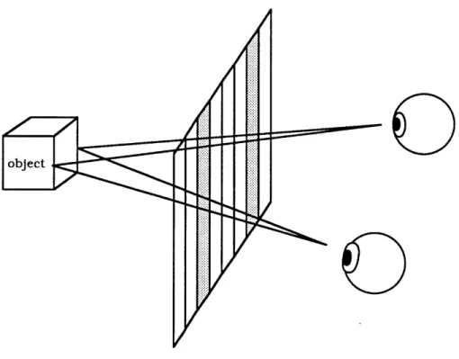
During the late 1960s, many researchers [Benton, 1975, 1982] worked on holographic methods of recording and combining sequences of many conventional photographic perspectives, in a manner similar to integral photography. Rather than recording different "views" of a scene on different parts of a plate through the use of a lens array, each view is recorded holographically, from the appropriate direction, on a small part of the holographic plate. The views are then spatially projected so that each eye of an observer sees the correct view for its position in order to yield a binocular or stereoscopic impression of depth. When the observer's head moves, different views are seen, providing motion parallax cues to depth [Fig. 2.2]. These optically multiplexed holograms have been called "holographic stereograms," or "stereograms" for short. They are also sometimes referred to as "Multiplextm" holograms, although this term refers to a specific type of commercial cylindrical stereogram and should not be used to describe the general technique.
F0
The information content of a hologram can be reduced considerably by eliminating vertical parallax so as to provide only one vertical view of the scene, producing a horizontal parallax only or "HPO" hologram [Fritzler and Marom, 1969]. Many types of stereograms eliminate vertical parallax so that only n rather than n2 views need to be rendered and recorded, where n is the number of independent side-to-side and up-to-down views presented by the scene. Vertical parallax is not needed by most viewers for accurate perceptions of distance, and Benton has shown that it could be traded for white light viewing [1969] and multi-color [1978] transmission holograms.
"Fully computer generated holography" - the actual computation and scribing of individual holographic fringes - has been developing since the mid-1960's [Tricoles, 1987] albeit at a slower pace than optical methods of synthetic holography. Until recently it was generally considered too difficult to compute the actual diffraction pattern, so approximations generally involving Fourier or Fresnel transforms were made instead. Fourier holograms do not normally have any depth in their images, although it is possible to use a number of them to project a sequence of 2-D views in manner similar to optically produced stereograms [Yaroslavskii,
1980]. In addition, HPO holograms can be computed with considerable
savings in time and information content, and there are special algorithms especially designed for three-dimensional lines and curves in computer graphics [Frere et.al., 1986]. Recently, the development of parallel architecture computers has also made more "optical" ray-tracing models feasible [Underkoffler, 1988]. Parallel computing may eventually be used to render many perspective views simultaneously, which could then be synthesized into a hologram by digital, analog, or optical means.
A great deal of interesting research on the transmission of holograms
occured at Bell Labs in the late 1960's, although little progress was made toward significant bandwidth reduction (with one important but non-electronic exception [Lin, 1968] which will be discussed later). Despite this lack of theoretical progress, simple static 2-D holograms were transmitted over video lines [Burckhardt and Enloe, 1968] and even over facsimile equipment in the Soviet Union [Yaroslavskii, 1980].
However, there is an important difference between generating and transmitting static 2-D holograms and moving 3-D ones. Several papers have been published recently on the feasibility of real-time holographic video, one on the use of computed HPO holograms [Boudreaux and Lettieri, 1987], and another that is more concerned with the synthesis of holograms from rendered or recorded images [Schultze, 1987]. Both papers suggest that major advances in display technology will be necessary to recreate holographic images in real-time.
Chapter 3.
Information Content and Bandwidth
This chapter explores the information content and requirements of holography, beginning with an overview of the sampling requirements, especialy as determined by the viewing zone size. Various methods of bandwidth reduction, especially elimination of vertical parallax and discrete sampling of perspectives, will be examined. Finally the author shows how resolution requirements can be reduced independently of bandwidth, and draws a distinction between transmitted and total hologram bandwidths.
3.1 Resolution Requirements of Optical and Electronic Holography
In a typical hologram, a range of perspectives views are modulated onto spatial carrier frequencies typically much higher than those in a conventional image. We can roughly determine the maximum spatial frequency in one dimension at any point on the hologram by using the first-order grating equation:
Xf =
I
sin9max-sin Oref
I
where 0max and Oref are the maximum angle of diffraction (or viewing angle) and the angle of the reference beam. A more precise analysis has
done [Leith, 1965] but this method is sufficiently accurate without requiring complex algebra, especially for synthetic holograms.
From the above it can be seen that for any band-limited hologram there will be a "forbidden zone" where at least part of the hologram will be unable to diffract light strongly enough to focus light onto a point within the zone [Fig. 3.1]. For a digital hologram this will lead to aliasing in if an insufficient number of sampling points are used (2n , where n is the number of cycles per unit distance according to the Sampling Theorem) for the resolution of calculated fringes.
3.2 Elimination of the Carrier Through Electronic Means
An on-axis hologram can also be used if another method is employed to separate the virtual, zero-order and conjugate images. This not only reduces the maximum carrier frequency for a given angle of view, but also eliminates the spatial sidebands inherent in the "heterodyning" process which separate the views in an off-axis hologram, for a 4:1 reduction in resolution requirements. Researchers at Bell Labs [Berrang,
1969; Burkhardt and Enloe, 1968] showed this was possible by recording 2-D
electronic holograms with 3 multiple exposures. The 3 on-axis holograms were recorded with different optical phase shifts and mixed with corresponding grating frequencies electronically. These were then sequentially photographed onto the same film to incoherently expose a spatial carrier-frequency hologram.
Enloe et. al. [1968] also showed that it should be possible to obtain a similar savings in bandwidth by scanning a thin reference beam across the photodetector surface, since the zero-order terms would then be constant whereas the desired first-order term would be time-varying. The virtual and conjugate images could be theoretically separated by using slightly
Viewing zone left edge of hologram
Viewing zone of right edge of hologram
11
Both edges of hologram will aliasWM
"Safe" zone3.3 Reduction of Diffraction Angles
Haines and Brumm [1968] and Hildebrand [1969] showed that was possible to reduce the required bandwidth by introducing a diffuser or other optical element in front of the hologram during recording and playback, thereby ensuring that at least some of the rays from all parts of the object are incident to the hologram at small angles. The latter suggested that the element could also be moved for a "time multiplexing" effect in addition to the spatial scattering. Of course, he admits that this means that many exposures would have to be incoherently superimposed on the same material, leading to drastic reductions of diffraction efficiency. The problem with the stationary method is the need for exact registration between the recording and playback apparatus with respect to the optical element, a severe disadvantage for a practical system.
3.4 Elimination of Vertical Parallax
Fritzler and Marom[1969], following the work of DeBitetto and others, realized that a large savings in information content could be obtained by using only one vertical perspective, thereby reducing the image to approximately its photographic resolution in the vertical direction. They predicted this lower the number of samples by a factor of
(4 r b sin~max / aX)
where a is the size of the object, b is the size of the hologram, and r is the resolution in the vertical or photographic image formed by a cylindrical lens.
3.5 View Sampling and Quantization
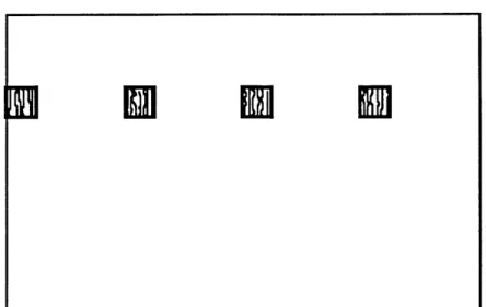
Even greater reduction of information can be had by also restricting horizontal parallax to a number of sampled views. The image of a Fourier transform hologram will remain stationary while the hologram itself is translated. Only the perpective of the object will change. It is possible to see all parts of a large object through a small Fourier hologram in this manner. Noting this, Lin [1968] showed that was possible to sample and repeat part of an approximate lensless Fourier transform hologram (a reference point source was located in the same plane as the center of a shallow 3-D object). A horizontal strip of the hologram was sampled even further by repeating small pieces of the horizontal spectra [Fig. 3.2] so that ideally each eye will see one view of reduced resolution. The resolution is directly related to sample width, which should be matched to the aperture of the human eye. Lin calculates this as
3 mm * (distanceobject->hologram)
/
(distanceobject->viewer) and shows test results for up to 1000:1 reduction in information content.Theoretically, Lin's technique is extremely interesting because it shows an exact relation between perspective and spatial carrier frequency; from a practical viewpoint it gives insight into the design of the video system described later.
3.6 Reduction of the Space-Bandwidth Product
While a certain number of elements might be needed for a holographic window of a given size there is no reason to assume that the all of these elements have to be displayed as a coherent whole. In fact, the acceptability of holographic stereograms would seem to indicate otherwise.
Fig. 3.2 Bandwidth reduction through sampling of a hologram (Lin)
In
~I ni
MF
11
dl2M
I~lE E
A typical holo-stereogram is in fact a set of incoherently exposed vertical
"strip" holograms which are each about 3 mm wide. Because stereograms at the Spatial Imaging Group are usually designed to accomodate a 30 degree field of view, we can expect that they have a space-bandwidth product of roughly (SIN 300 / 633 x 10-6 mm) = 790 cycles /mm * 3. mm =
2370 cycles for each exposure in the horizontal direction. It should be also
noted that these images are of very high quality, limited chiefly by the film exposure hardware. (3mm is a typical aperture for stereograms since this is roughly the diameter of the human iris under normal viewing conditions.)
For a "soft-copy" or actively refreshed display we can take advantage similar reduction of information by scanning a smaller "sub-window" across a larger hologram plane just as a raster is scanned across a television screen. This means only bandwidth rather than resolution is important, provided that the modulator has a high enough space-bandwidth product to provide an adequate image. In fact, the pixel density of the modulator is not important - the modulated image can be optically reduced through a telescope to produce a wider viewing zone. The diffracted light rays passing though the reduced modulator image are bent as if they passed though a grating of the same spatial frequency of (Fig. 3.3).
(x iz1)
I~IzjIIIiiIiIIi I
I I I I I JiiIii~
(x 2' z2)
Point (on modulator) at (x1, zi) gets imaged at (x2, z2) = (= 11, m2zi)
where m = transverse magnification, m2 = longitudinal magnification
tan 01 = sin 01 = /zi = fi
tan 02 sin 02 = mx1/m 2z1 = Xfi/m = Xf2
fi and f2 are the spatial frequencies in the modulator and its image, respectively
f2 = fi/m and Xf = sin 0 (grating equation)
3.7 Internal vs. External Bandwidth
A distinction should also be drawn between the internal bandwidth of the
holographic display, and the external or transmitted bandwidth of the system. There is a tradeoff between the latter and the amount of computation and/or signal processing necessary in the receiver. An ideal system would eliminate all of the redundancy of a three-dimensional scene prior to the transmission of its image representation. In practice, either a coded 3-D model of the scene or rendered key views might be transmitted in the holographic television system of the future, and a hologram synthesized in the display [Yaroslavskii, 1980]. As stated above, the high frequencies inherent in holography are necessary not for adaquate image information but for a wide viewing zone, so it should be possible to do this with no loss in image quality. However, in the system described here a hologram is computed ahead of time and sent along a high-bandwidth fiber-optic or coaxial cable system, enabling all of the "brains" of the system to be on the transmitting end provided that sufficient bandwidth is available. A computed hologram is stored in a
frame buffer, transmitted, and mixed with a higher frequency local oscillator. (This is necessary for the modulator, which has only an octave of useful frequency range). An analysis of the resulting wider viewing zone and image distortions will be shown later.
Chapter 4
Design of the MIT System
The following details the work performed at the MIT Spatial Imaging Group by the author and his colleagues.
4.1 Hologram Sources and Computation
A set of horizontal line holograms was computed by modulo ray-tracing of
points and lines [Underkoffler, 1988]. Massively parallel hardware makes it practical to model the actual propagation of light, rather than simply approximating Fraunhoffer or Fresnel diffraction as is more typical for fully computer generated holograms.
The display is not dependent on any particular kind of hologram except that it must be made of a number of horizontal line holograms. The horizontal and vertical scan rates canbe altered to match the source (within the physical constraints of the scanning mechanisms) and the number of pixels is limited by the bandwidth of the system, with optical adjustment of the image as necessary. For example, this system might eventually be adapted to display holograms synthesized from video sources in real time [Kollin, 1988; Schultze, 1987].
4.2 Interfacing and Hardware Requirements
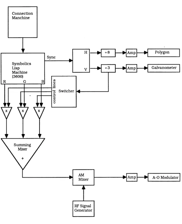
Holograms are generated on the Connection Machine 1 computer and presented on a RS-343 compatible Symbolics Lisp Machine hi-res (1.2K x
the sync line effectively reformat the frame buffer so that each color is read out serially in order to yield an effective 40,960 x 96 resolution holographic viewing window which is refreshed every tenth of a second. New frames cannot yet be loaded quickly enough for real-time animation due to I/O
speed limitations. Real-time generation of holograms for continuous smooth animation would require either specialized hardware such as a
CM2 upgrade to add floating point arithmetic and high-speed I/O or a high
resolution videotape system to play back precomputed frames.
The chief advantage of the Lisp Machine is its software-configured frame buffer, which make modifications very easy compared to hardware modifications on a typical high resolution frame buffer. Because the retrace intervals can be made very short, gaps in the hologram can be minimized. Some custom hardware is necessary to switch between the Red, Green, and Blue lines of the frame buffer, and to divide down the horizontal and vertical synch signals, which then drive the horizontal (polygon scanner) and vertical (galvanometer) scanning systems [Fig. 4.1]. For a more practical system, a custom frame buffer that could handle a higher sampling rate and overall capacity would probably be more desirable.
4.3 Optical Engineering
4.3.1 Overview
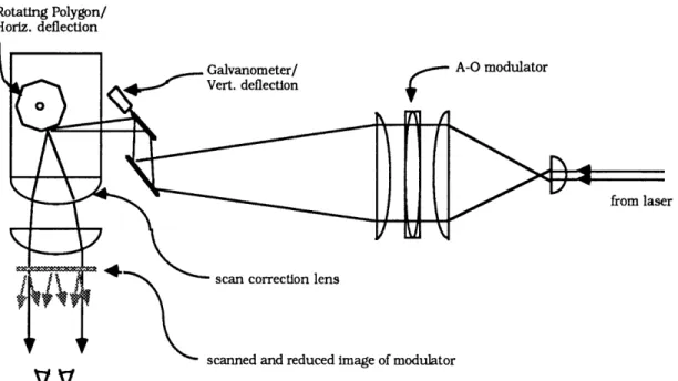
Cylindrical and collimating lenses are used to fan out and collimate the light to illuminate of the A-O modulator. The modulator image is then de-magnified by an inverted telescope (afocal lens system) [Kingslake, 1983] in order to increase the angle of diffraction to the 12 degree design goal
(330 cycles/mm). The image is then reflected from a rotating polygon
system that is capable of scanning from left to right with a minimal retrace interval [Fig. 4.2]. The resulting "line hologram" is reflected from a vertical scanning galvanometer mirror so as to sequentially sweep out a
3-D space . (Actually, the vertical deflection occurs just before the rotating polygon which is much easier. This also allows the use of one spherical scan lens rather than two cylindrical ones.)
Note that in this system the modulator is illuminated with collimated light. The illumination and projection optics can be changed for Fourier or diverging reference holograms, but we decided to keep the system as conceptually simple as possible for the present.
When a high resolution 2-D liquid crystal, electro-chromic, or photo-chromic modulator is available it will probably be read out in a simple off-axis transmission mode. Until then, some type of scanning system - horizontal and/or vertical - will be necessary to fill out a large "virtual" array size.
Rotating Polygon/ Horiz. deflection
Galvanometer/
Vert. deflection r A-0 modulator
from laser
scan correction lens
scanned and reduced image of modulator
vv
We can estimate:
(50mm wide)*(330 cycle/mm)*(2 pixels/cycle) = 33000 pixels
as the minimum size for our holographic window. As it was impossible to obtain a modulator capacity of 33000 pixels, we decided to scan the modulated holograms horizontally as well as vertically in order to meet the original design goals of the project. This led to the realization that a modulator of much lower space-bandwidth product could be used if a carefully matched scanning technique was employed. The viewing window was to be composed of 96 lines, each of which is composed of 40,960 pixels. For this device, the modulator is a commercially available TeO2 acousto-optic deflector device and the horizontal scanner is a rotating mirror polygon system salvaged from a FAX machine. Lenses are used to reduce and image the modulator after the polygon, so that the modulator image is swept to fill out the full line hologram. A continuous-output laser (such as a helium-neon) can be used with a serially addressed modulator as long as the propagation speed of the optically reduced image of the hologram along the modulator is equal to and opposite that of the horizontal scan rate, so that the relative movement of the hologram projected into the viewing window is as close to zero as possible (Fig. 4.3). If a 50 mm line is swept out every 1/960th of a second and the hologram propagates down the TeO2 crystal at .612 mm/s, we need a reduction of:
The image should remain stable as long as the system is synchronized, but some blurring may result if there is relative movement of the hologram
due to error in the size reduction. Small adjustments can be made by adjusting the optical elements until image blur is minimized.
- -ca nin -- f----. - -- - - --- - --
-..
The reduced image of the modulator can be considered as a viewing "sub-window" on a larger hologram scanned by the polygon system. As stated above, only bandwidth rather absolute resolution is important in this system, provided that the modulator has a high enough time(space)-bandwidth product to provide an adequate image. For this system, a 330cycle/mm * 3mm = 990 cycle modulator might be adequate
although the additional capacity will presumably reduce noise and improve resolution. Quantization noise is not a significant problem since the display is being driven by the output of a frame buffer with 8 bits per sample.
The optical engineering of the scanning and lens systems is based on well developed "off-the-shelf" components, even though our application is different than most. Most scanning technology is based on the typical system requirement of scanning a finely focused spot across a 2-D surface, rather than translating an image with minimal distortion. In fact, this system might be best viewed as a device for raster scanning a (constantly changing) HPO hologram rather than a typical spot. Some image degradation is inevitable as the system must accurately image a high-resolution structure through relatively "fast" (low f-number) optics of imperfect quality and light is scattered from many uncoated optical surfaces to produce noise and flare.
4.3.2 Output Devices
Acousto-Optic Modulators
Acousto-Optic modulators are the technology chosen for the initial prototype. The principal materials considered are "slow" so as to provide
the maximum time-bandwidth product for a given device (crystal) size. The theory is described in detail in [Chang, 1976, 1985]. Basically, the signal is mixed with an RF signal of constant frequency and amplified to about 1 watt prior to insertion into the device. A transducer converts the electrical signal into acoustic waves which then travel across the crystal and induce index of refraction variations proportional to the compression and rarefraction of the crystal lattice. This effectively creates a phase hologram that travels across the modulator window until it reaches the termination on the other end. Modulator "resolution" is the space-bandwidth or time-bandwidth product, which are equivalent to each other (the "bandwidth" in space-bandwidth is the range of spatial frequencies).
So far the slowest practical material available off the shelf is TeO2 (tellurium dioxide) operating in the slow-shear mode with an acoustic speed of .62 mm/psec, for a total delay time of up to 70-100 secs (given currently available crystal sizes). It may eventually be possible to use mercurous halide modulators which are only 56 percent as fast as TeO2, providing a corresponding increase in T-B product for a given crystal size. In addition, it may eventually prove possible to grow these crystals larger than TeO2. However, such devices are not available commercially at this time, and because of greater attenuation at high frequencies they have a lower bandwidth than readily available TeO2 devices.
The modulator chosen for the prototype has a 56 microsecond delay time and a 45 MHz bandwidth for a time-bandwidth product of (56 * 45) = 2530
amplification and insertion in the modulator as is typical for A-O devices. This is necessary to limit the bandwidth of the input signal to only one octave of operating range in order to prevent aliasing. The resulting upconversion will cause some distortion as the higher frequencies result in a disproportionately larger increase in the deflection angle, which increases with SIN-1(f) rather than linearly. A more appropriate solution would be to compute the hologram for this frequency range directly, modelling an off-axis reference beam and eliminating the need for an external local oscillator. Of course, this would require a higher frequency output from the digital hardware.
GaP (gallium phosphide) A-O modulators with a bandwidth of at least 1 GHz and a T-B product of 1000 are also available from Crystal Technology and Brimrose. If we are content with a viewing zone of 12 degrees, it seems quite possible to build a 500 line, 30 Hz display which is:
109 Hz -- ((500 lines/screen * 30 screens/sec) * 330 cyc/mm) = 200mm/line
[Bandwidth + (lines/sec * spatial frequency) = line width]
across using current technology for the display. The electronics necessary to drive such a system would be considerably more expensive and difficult to obtain, however.
Acousto-optic modulators are not the only method of high frequency spatial modulation of a laser beam, although they are particularly well suited for the system described in this paper because of the traveling-wave serial addressing. Other technologies are described in great detail in
another Master's thesis [Parker, 1988]; however, their present capabilities can be briefly mentioned here for comparison.
Oil film or Eidophor devices were suggested by Leith [1965] as a possible means for display electronically transmitted holograms, noting that 100 cycles/mm was obtainable. In this device, a rotating plate is coated with a film of oil, which is deformed by a charge induced by a scanning modulated electron beam. The resulting thickness variation corresponds to a phase modulation which slowly decays as the charge dissipates. One can imagine a system where a rotating disk is continually scanned with a electron beam while laser light passes through it into a system similar to that described above. Even finer resolution can be obtain by scanning a photochromic material with a laser, however the greater power requirements make this less practical at present.
Liquid crystals [Efron et. al., 1983] [Welkowsky et. al., 1987] are also starting to be produced in the resolution range suitable for holographic display given the generous standards established here. A major problem with
LCD displays has been their refresh rate; 30 Hz is now commonplace but
obviously this will not do for a scanned modulator image. The fastest liquid crystals - ferroelectrics - also have a very limited grey-scale capability
4.3.3 Scanning Systems
The horizontal scanning system is based on a mirrored octagon which continually rotates in synchronization with a signal derived from the frame buffer. In addition to reconfiguring for the long line lengths, each signal must be divided down by another factor of 8 because each facet
(2 * 360 / n) degrees
where n is the number of facets, giving a 90 degree angle of scan for an octogon. The factor of two occurs because the incident angle is equal to the angle of reflection. The polygon scans at a constant angular rather than linear speed, producing a curvature of field and causing the scan to be faster at the ends than at the center. This is especially bad for large scan angles but can be corrected by a field-flattening or 'f-O' lens that ideally produces a linear scan [Beiser, 1984]. In addition to any flaws in this lens, the system can suffer from misalignment or rotational irregularities in the polygon or the motor. These can be reduced to a few arc-seconds with more expensive components.
The considerably slower vertical scanning or 'screen refresh' rate is achieved with a galvanometer mounted with a front surface mirror and driven with an audio amplifier buffered with a 741 op-amp. The deflection of the mirror follows a ramp waveform generated from the divided sync signal, providing a retrace time conservatively estimated at
1/100th of a second.
4.3.4 Imaging Optics
The optical system that degmagnifies and images the modulator hologram window must allow the highest frequencies of the hologram to pass though. While time and money do not permit more than a first-order design in term of image distortion, the spatial frequency response of an unaberrated coherent optical system simply drops from 1 to 0 at the
equivalent Fourier transform component at the edge of its entrance or exit aperture [Goodman, 1968], whichever is more limiting. Therefore if all of the first-order diffracted light is passed through the system for the desired frequency range of the modulator, the only optical loss will be in the aberrations and scatter.
4.4 Additional Remarks
While the discussion above of system quality issues may give the impression that system tolerances were tight, quite the opposite was true. Because the horizontal scanning occurs in the approximate Fourier transform plane of the image the overall system was quite tolerent of errors. As long as the projected hologram is roughly the appropriate view, stereopsis should result for the viewer who may not notice small or slowly changing deviations in the image. These will typically take the form of small variations in depth as the perspectives shift slightly from their appropriate positions. Except for very deep images, which would be then be scanned away from the Fourier plane, there should be little translation of the image during the scan - only the projected viewpoint should change as described in Lin [1968].
Chapter 5
System Performance
Equipment problems delayed the testing of the system as a whole until the very end of the study. However, we were finally able to see line images composed of points with some apparent depth. At first there was no vertical deflection, but we were able to see stable points in the horizontal line image. After the vertical scanning circuitry was debugged, we started to have problems loading the software-reconfigured frame buffer. After reconfiguring it for a second time, we saw "jittery" images in which the points moved back and forth very quickly, as if they were tracing out their perspectives in a totally unsynchronized manner. Fortunately, we were able to see them by using the vertical deflection to "strobe" the line image.
A deeper test image was considerably more jittery than the shallow one,
which is not surprising because it has more disparity and points are scanned further away from the Fourier transform plane, thereby increasing the error. No attempt has yet been made to display more than a repeated single line hologram.
The small viewing zone also made it difficult to verify horizontal parallax. This was due to the limited aperture and offset of the scanning polygon as seen in Fig. 4.2. The polygon and motor are permanently mounted in an aluminium casting with little chance of effective modification. Some distortion from the off-center alignment of the polygon and scan lens was observable and it was difficult to fit a complete image into the viewing
zone. The problem was somewhat mitigated by using a stronger lens before the polygon, but this lead to less demagnification of the modulator image, making it harder to observe parallax. Another problem was the 90 degree scan of the the octagon. In order to collimate all of the light reflected by the scanner, an f/1 lens would be needed. Such lenses tend to be expensive and produce distortions. A polygon more suited to the system requirements (on-axis with a greater number of facets) would improve both the viewing zone and optical quality of the image.
Nevertheless we hope to obtain a full 3-D image in the near future. All of the hardware appears to work except the RGB switcher (which would triple the number of lines from 32 to 96) and the system is now capable of 2 dimensional scanning of the hologram window. The vertical scanning is restricted by the polygon system, where the polygon height and aperture permit only a limited amount of vertical deflection. We anticipate more complete results after we locate our synchronization problem(s), even though it may not prove possible to meet the original design parameters with the current polygon scanner. We expect to obtain enough horizontal parallax to take stereoscopic photographs of the image.
The next step will be to make the system more robust and then add the full number of lines. Redesigning the optics and using a more appropriate polygon scanner is also a high priority. The construction of a dedicated, high-speed frame buffer to drive a higher bandwidth modulator for a larger image would then follow as a longer term goal.
Chapter 6
Summary and Conclusions
The author has shown that the resolution requirements of holography can be reduced enough to take advantage of readily adapted off-the-shelf hardware in to create an electronic hologram display, and eventually to provide real-time holographic animation. By eliminating horizontal
parallax and scanning a relatively "small" modulator image, it becomes possible to fill out a larger holographic window with enough resolution to satisfy a human observer's eye.
Hologram size and viewing angle are limited by the bandwidth of the driving circuitry and modulator, rather than their resolution or time-bandwidth product as previously assumed. Because most of this bandwidth is due to carrier frequencies which can be added locally, it follows that holographic television is dependent primarily on the ability to transmit either a three-dimensional model of a scene or appropriate renderings of it. There is still much work to be done in the application of
3- or 4-dimensional signal processing to spatial imaging in general, and
we can expect that this will lead to even greater reductions of bandwidth for moving 3-D images. It is the author's opinion that this is where future research should be concentrated in conjunction with efforts to improve the display.
References
Beiser, L. (1984). "Resolution of Laser Scanners", Opt. Eng., Vol. 23, pp.
266-272
Benton, S. A. (1969). "Hologram Reconstructions with Extended Incoherent Sources,"
J.
Opt. Sci. Amer. Vol. 59 pp. 1545-1546.Benton, S. A. (1975). "Holographic Displays - a Review," Opt. Eng., Vol. 14,
pp. 402-407.
Benton, S. A. (1978). "Achromatic Images from White-Light Transmission Holograms,"
J.
Opt. Soc. Amer. Vol. 68 pg. 1441.Benton, S. A. (1982). "Survey of Holographic Stereograms," SPIE Vol. 367,
pp. 15-19.
Boudreaux and Lettieri (1987), "Toward Real-Time Animation of Holographic Video Images," SPIE Vol. 845.
Burckhardt and Doherty (1968), "Formation of Carrier Frequency Holograms with an On-Axis Reference Beam," Appl. Opt. Vol. 7, pp.
1191-1192.
Burckhardt and Enloe (1969), "Television Transmission of Holograms with Reduced Resolution Requirements on the Camera Tube," Bell System Technical Journal, May-June 1969.
Chang I. C. (1976), "Acoustooptic Devices and Applications," IEEE Transactions on Sonics and Ultrasonics, Vol. su-23, No. 1.
Chang, I. C. (1985). "Selection of Materials for Acousto-Optic Devices," Opt. Eng., Vol. 24, pp. 132-137.
Denisyuk, Yu. N. (1963) "On the Reproduction of the Optical Properties of an Object by the Wave Field of its Scattered Radiation," Optics and Spectroscopy, Vol. 15, pp 279-284.
Enloe, Jakes and Rubinstein (1968), "Hologram Heterodyne Scanners," Bell System Technical Journal, November 1968.
Enloe, Murphy and Rubinstein (1966), "Hologram Transmission via Television," Bell System Technical Journal, February 1966.
Frere, Leseberg, Bryngdahl (1986), "Computer-Generated Holograms of Three-Dimensional Object Composed of Line Segments,"
J.
Opt. Soc. AmA, Vol. 3, pp. 726-730.
Frere, and Bryngdahl (1986), "Computer-Generated Holograms: Reconstruction of Curves in 3-D," Opt. Comm., Vol. 60, pp. 369-372.
Fritzler and Marom (1969), "Reduction of Bandwidth Required for High Resolution Hologram Transmission," Applied Optics Vol. 8, 1241-1243.
Goodman,
J.
W. (1968), Introduction to Fourier Optics, McGraw-Hill, pp.110-113.
Haines and Brumm (1968), "Holographic Data Reduction," Appl. Opt. Vol.6, pp. 1185-1188.
Hildebrand, B.P. (1970), "Hologram Bandwidth Reduction by Space-Time Multiplexing,"
J.
Opt. Soc. Am., Vol. 60, pp. 259-264.Kollin,
J.
S. (1988), "Collimated View Multplexing: A New Approach to 3-D Imaging," SPIE Vol. #902.Leith and Upatnieks (1964), "Wavefront Reconstruction with Diffused Illumination and Three-Dimensional Objects,"
J.
Opt. Soc. Am., Vol. 54,pp. 1295-1301.
Leith, Upatnieks, Hildebrand and Haines (1965), "Requirements for a Wavefront Reconstruction Television Facsimile System,"
J.
SMPTE Vol. 74, pp. 893-896.Lin, L. H. (1968), "A Method of Hologram Information Reduction by Spatial Frequency Sampling," Appl. Opt. Vol. 7, pp. 545-548.
Parker, W. (1988), "Modulation Devices for Electronic Dynamic Holography," S.M. Thesis, Massachusetts Institute of Technology, 1988.
Schultze, E. (1987), "Real-Time Holographic 3D Imaging Based on Multiplexing Techniques and Optoelectronic Holograms," SPIE Vol. 812 Progress in Holography, 1987.
Tricoles, G. (1987). "Computer generated holograms: a Historical Review,"
App. Op., Vol. 26, pp. 4350-4390.
Underkoffler,
J.
(MIT), "Development of Parallel Processing Algorithms for Real-Time Computed Holography," S.B. Thesis, Massachusetts Institute of Technology, 1988.Welkowsky, Efron, Byles, Goodwin (1987), "Status of the Hughes Charge-Coupled-Device Addressed Liquid Crystal Light Valve," Opt. Eng., Vol. 26, pp. 414-417.
Yaroslavsii [aka Iaroslavskii] and Merzlyakov (1980), Methods of Digital