Design and Implementation of a Pair of Robot Arms
MASSACHUSETTS INSTITUTEwith Bilateral Teleoperation
OF TECHNOLOGYby
JUL 16 2019
Alexander Hattori
LIBRARIES
ARCHIVES
Submitted to the Department of Mechanical Engineering
in partial fulfillment of the requirements for the degree of
Bachelor of Science in Engineering as Recommended by the Department
of Mechanical Engineering
at the
MASSACHUSETTS INSTITUTE OF TECHNOLOGY
June 2019
@
Massachusetts Institute of Technology 2019.
A uthor ...
All rights reserved.
Signature redacted
)epartment of Mechanical Engineering
Ma 17, 2019
Signature redacted
C ertified by ...
angbae Kim
sociate Professor
Thesis Supervisor
Signature redacted
A ccepted by ...
IMaria Yang
c
Associate Professor of Mechanical Engineering, Undergraduate Officer
Design and Implementation of a Pair of Robot Arms with
Bilateral Teleoperation
by
Alexander Hattori
Submitted to the Department of Mechanical Engineering on May 17, 2019, in partial fulfillment of the
requirements for the degree of
Bachelor of Science in Engineering as Recommended by the Department of Mechanical Engineering
Abstract
Modern robotics has progressed in the manufacturing industry so that many manual labor tasks in assembly lines can be automated by robots with high speed and high positional accuracy. However, these robots typically cannot perform tasks that re-quire perception or disturbance rejection. Humans are still needed in factories due to their innate ability to understand situations and react accordingly. Teleoperated robots can allow human perception to be combined with the dexterity and safety of a robot as long as the user interface and controls are carefully designed to avoid hinder-ing the operator. Force feedback bilateral teleoperation is one method for providhinder-ing users with an intuitive user interface and feedback. This thesis documents the design, construction, and implementation of a pair of bilateral teleoperated robotic forearms, each consisting of a 2 degree of freedom wrist, and a gripper. The forearm uses com-mercial off the shelf actuators in order to keep cost and additional development time
low, while also testing the feasibility of using non-custom actuators. Development of
the forearms included design and manufacturing of the mechanical assemblies, imple-mentation of high-speed communication protocol, and tuning of control parameters.
Thesis Supervisor: Sangbae Kim Title: Associate Professor
Contents
1 Introduction 9 1.1 M otivation . . . . 9 1.2 Scope ... ... 9 1.3 Thesis Organization. . . . . 10 2 Design 11 3 Manufacturing 15 3.1 G ripper . . . . 15 3.2 W rist/Arm . . . . 17 4 Software Implementation 25 4.1 C ontrols . . . . 25 4.2 Dynamixel Communication . . . . 26 4.3 RS-485 Implementation . . . . 275 Summary and Conclusions 33
List of Figures
1-1 Mechanical forearm assemblies . . . . 10
2-1 Arm assembly and forearm assembly . . . . 11
2-2 Wrist differential . . . . 12
2-3 Gripper assembly . . . . 12
3-1 Parallel gripper links . . . . 15
3-2 Parallel gripper links after each operation . . . . 16
3-3 Finished machined spur gears . . . . 16
3-4 A finished mechanical gripper assembly, and two completed grippers . 17 3-5 Wrist triple bearing block . . . . 17
3-6 The manufacturing process to make the wrist bearing block . . . . 18
3-7 Soft jaw flange clearance . . . . 19
3-8 Haas probe clearance . . . . 19
3-9 Completed timing pulley . . . . 20
3-10 Completed forearm structure . . . . 20
3-11 Plastic damping blocks glued in for machining . . . . 21
3-12 Additional soft jaws for machining forearm structure . . . . 21
3-13 Spacer block used for bearing presses . . . . 22
3-14 Completed forearm assembly and additional completed gripper . . . . 23
4-1 Motor Position Tracking ... . . . . 26
4-2 RS-485 Bus . . . . 27
4-4 OpenCM9.04 Serial Bus . . . . 29
4-5 Decoded serial message . . . . 29
4-6 Control loop frequency shown on channel 3. . . . . 30
4-7 Decreased status response time . . . . 31
Chapter 1
Introduction
1.1
Motivation
Modern robotics has progressed in the manufacturing industry so that many manual labor tasks in assembly lines can be automated by robots with high speed and high positional accuracy. However, these robots typically cannot perform tasks that require perception or disturbance rejection. Humans are still needed in factories due to their innate ability to understand situations and react accordingly. Therefore, because a conventional autonomous robot is not always suitable, human health and life is often put at risk on a factory floor doing laborious tasks like welding and grinding. Teleoperated robots can allow human perception to be combined with the dexterity and safety of a robot as long as the user interface and controls are carefully designed to avoid hindering the operator. Force feedback bilateral teleoperation is one method for providing users with an intuitive user interface and feedback.
1.2
Scope
This thesis documents the design, construction, and implementation of a pair of bilat-eral teleoperated robotic forearms, each consisting of a 2 degree of freedom wrist, and a gripper. Each forearm assembly will be attached to an already existing 3 degree of freedom teleoperated robot arm to provide additional user degrees of freedom. The
forearm uses commercial off the shelf actuators in order to keep cost and additional
development time low, while also testing the feasibility of using non-custom
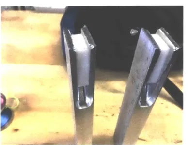
actu-ators. Figure 1-1 shows the completed mechanical assemblies of the two forearms.
Development of the forearms included design and manufacturing of the mechani-cal assemblies, implementation of high-speed communication protocol, and tuning of
control parameters.
Figure 1-1: Mechanical forearm assemblies
1.3
Thesis Organization
"
Chapter 2 details the design of the forearm assemblies." Chapter 3 details the in-house manufacturing of the forearm assemblies. " Chapter 4 details the software and controls implementation of the forearm
assemblies.
Chapter 2
Design
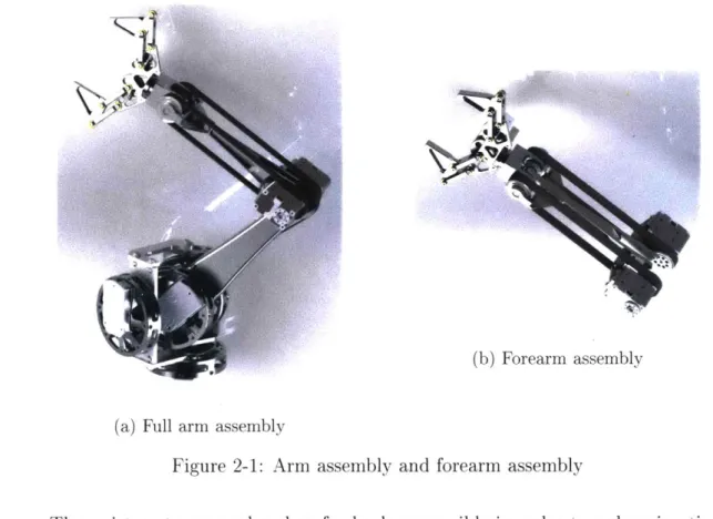
The forearm was designed to be appended to an already existing 3 degree of freedom
arm developed by Ben Katz. Figure 2-la shows the assembly in the context of the
full arm. The forearm assembly is shown on its own in Figure 2-1b.
k~
(b) Forearm assembly
(a) Full arm assembly
Figure 2-1: Arm assembly and forearm assembly
The wrist motors are placed as far back as possible in order to reduce inertia of the forearm assembly. The motors take up almost 20% of the mass of the forearm so keeping them close to the rotational axis was important. They were not placed any
farther back in order to keep the original 3 degree of freedom arm unaltered. The wrist uses a bevel gear differential, shown in Figure 2-2, which allows the wrist to
rotate indefinitely (if not for the gripper wiring).
Figure 2-2: Wrist differential
This differential also allows the wrist to utilize the power of two motors.
When-ever either wrist degree of freedom (bending or rotating) is used independently, both motors can provide torque, effectively doubling the power.
The gripper, shown in Figure 2-3, was designed to be simple and easy to swap.
Figure 2-3: Gripper assembly
Typically, one robotic gripper attachment is not effective for all scenarios so for
the purpose of testing, a simple parallel linkage gripper was used, with the actuator put on the gripper itself. The gripper is attached with a bolt and pin circle and can be swapped for any other tools/attachments in the future. In order to minimize backlash, gears with small pitch were used to transmit torque from the driven to non-driven side of the gripper.
.1
Chapter 3
Manufacturing
Most parts used in this thesis were carefully designed to be as lightweight as possible
while maintaining structure, which made the in-house manufacturing more
compli-cated.
3.1
Gripper
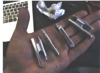
The gripper consisted of many small parts which were all made on a Dyna-Myte 1007
CNC mill in MITERS. The parallel gripper links are shown in a hand for scale in
Figure 3-1.
I
Many parts made for this thesis required multiple setups and fixturing and so an
example of the process of making a single gripper link is shown in Figure 3-2.
Figure 3-2: Parallel gripper links after each operation
The machined gears, shown in Figure 3-3, were parted off spur gear stock, and then post machined on the CNC mill.
Figure 3-3: Finished machined spur gears
A completed mechanical gripper assembly and a pair of finished grippers with
Figure 3-4: A finished mechanical gripper assembly, and two completed grippers
3.2
Wrist/Arm
The parts for the wrist/arm required more fixturing, and so in order to save time, the rest of the machining was done on a Haas VF2 and Haas Super Mini Mill due to their higher power spindles, and zeroing probe.
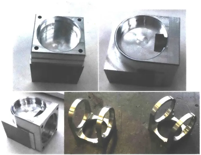
The wrist bearing block, shown in Figure 3-5, was one of the most difficult parts
to machine due to its need for accuracy, combined with its spindly design.
Figure 3-5: Wrist triple bearing block
This part was made in four setups, with the last one removing the majority of the
Figure 3-6: The manufacturing process to make the wrist bearing block
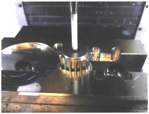
The timing pulleys were made from existing timing pulleys and required unique
fixturing and zeroing. In order to hold the pulley in the vice, a channel had to be milled in the soft jaws to clear the flange. The flange clearance channel is shown in
Figure 3-7.
Figure 3-7: Soft jaw flange clearance
The Haas zeroing probe only barely fit in the stock pulley bore, but it was still
successful. The clearance is shown in Figure 3-8.
Figure 3-8: Haas probe clearance
Figure 3-9: Completed timing pulley
In order to make the main forearm structural piece, shown in Figure 3-10, plastic
blocks (Figure 3-11) had to be glued in between operations to add damping and structural rigidity while machining, and more soft jaws had to be machined (Figure
3-12).
t
Figure 3-11: Plastic damping blocks glued in for machining
Figure 3-12: Additional soft jaws for machining forearm structure
Final assembly of the wrist is semi-permanent and so extra care was taken to not damage any of the spindly parts during assembly. Figure 3-13 shows the spacer blocks
Figure 3-13: Spacer block used for bearing presses
Chapter 4
Software Implementation
4.1
Controls
Each joint in the forearm assembly utilizes pseudo-impedance control in the form of a symmetric PD controller. The difference in position between the two joints is used to calculate the correcting torque. The proportional term acts as the spring constant, and the derivative term provides damping. This PD control is done on each joint directly on the actuator, a Dynamixel XM-430. Each joint attempts to maintain the position on the corresponding joint on the other forearm.
In order to create a realistic haptic feedback experience for the user, in particular when one joint encounters a very stiff obstacle, the individual joints need to be very stiff. This requires a large proportional gain. However, with too high of a propor-tional gain, the system tends to go unstable as the actuators overshoot. Damping can be used to make the system more stable, but this damping affects the user experience because it can be felt as drag in the system. The maximum stable proportional gain can be increased as long as the control bandwidth increases and thus,
communica-tion and control loop speed were heavily emphasized in the software implementacommunica-tion for this project. Figure 4-1 shows position data of two wrist joints trying to track each other's position. Overshoot and underdamping can be seen between 2000-3000 milliseconds.
2100 2000 1900 1800 1700 1600 1500 1400 1300 1200 1100 2000 3000 4000 Time (ms) 5000 6000 7000
Figure 4-1: Motor Position Tracking
4.2
Dynamixel Communication
Communication with the Dynamixel occurs over RS-485 differential serial. An exam-ple of the RS-485 protocol for the Dynamixel is shown in Figure 4-2. Although there
are two signals, only on'e send or receive can be on the bus at a time because the two
signals form a differential pair.
Timing is important in order to prevent corrupt data because all messages are sent and received on the same bus. Position data is retrieved over this serial bus
from the built in 4096 steps/turn absolute encoder on the Dynamixel, and new gains
and position setpoints can be set by sending serial messages. Additional parameters
like temperature, current, and feedforward gains can also be retrieved or set on the Dynamixel but were not used for this implementation [2].
U 0 0
0,
C
Motor position tracking
Motor 1 Motor 2
AI
Figure 4-2: RS-485 Bus
4.3
RS-485 Implementation
Initial communication was done using an OpenCM9.04 microcontroller which contains
an STM32F103. The Dynamixel library from Robotis was used but performance was poor. Even with only a single degree of freedom enabled, the proportional gain could
not be set high enough to resist a human's finger strength without going unstable, unless large amounts of damping was used. Figure 4-3 shows the debugging setup
-j
Figure 4-3: Debugging setup for RS-485
Using an oscilloscope and its built-in serial decoder, the issue with the initial
software implementation became very clear. Figure 4-4 shows a few messages being sent and received on the serial bus.
- - -- - --- - - --- __ -A
Figure 4-4: OpenCM9.04 Serial Bus
Figure 4-5 shows a decoded serial message sent to the Dynamixel.
Figure 4-5: Decoded serial message
Although the messages were being sent and received from the Dynamixel at IM
baud, there were large delays between messages being sent or received. With all three
forearm degrees of freedom enabled, the control loop ran at around 65 Hz, as shown
Figure 4-6: Control loop frequency shown on channel 3.
One simple improvement involved decreasing the status message delay time on the Dynamixel. Whenever the Dynamixel receives a message, it replies to the serial bus
with a status message. By default, the Dynamixel delays 500 microseconds before
responding with this message in order to ensure the serial has finished sending its
message, but due to the frequency and repeatability of commands used to control the forearms, that delay time can be reduced significantly. The initial improvement can
be seen in Figure 4-7 where a reduced latency message is sent, followed by a normal latency message, and a reduced latency message.
Figure 4-7: Decreased status response time
While this did improve communication speed marginally, there are still large gaps between messages sent. Thus, a new implementation of RS-485 for a different
micro-controller was written. Using the ARM MBED Serial library and an STM32F446, communication at 115K baud could be achieved in a few lines of code. IM baud signals dropped bytes and was not achievable using the Serial library's functions. At
115K baud, the delay time between messages was removed, and a control bandwidth
of 193 Hz for the three degrees of freedom was achieved. An oscilloscope screenshot of the serial bus is shown in Figure 4-8.
Figure 4-8: Serial bus with MBED serial library communication.
Serial bus with MBED serial library communication. Channel 2 shows the control loop frequency, and Channel 3 shows the communication signals directly.
At 115K baud communication performance was maximized because messages were
always being sent or received, with no idle time. However, communication could still be improved.
In order to achieve IM baud communication on the STM32F446, Direct Memory Access or DMA had to be implemented because the processor was unable to read all the serial data fast enough.
DMA utilizes a hardware subsystem on the microcontroller to watch for incoming
serial bytes on the microcontroller, and automatically store them in a buffer so that
the processor can access the data in the buffer when it is ready. For this implementa-tion of IM baud serial, DMA was only used for receiving data because the processor could already send serial bytes at IM baud. A future software revision will implement DMA for serial sending as well, in order to increase serial communication to speeds
around 4.5M baud which is the fastest communication the Dynamixel supports [1. With 1M baud communication, a control bandwidth of around 700 Hz could be achieved with all three degrees of freedom pairs on one microcontroller. A notable
stiffness increase was seen, and less damping was needed, leading to a better user experience.
Chapter 5
Summary and Conclusions
5.1
Design Summary
This thesis documents the design, construction, and implementation of a pair of bilat-eral teleoperated robotic forearms, each consisting of a 2 degree of freedom wrist, and a gripper. The forearm uses commercial off the shelf actuators in order to keep cost and additional development time low, while also testing the feasibility of using non-custom actuators. Development of the forearms included design and manufacturing of the mechanical assemblies, implementation of high-speed communication protocol, and tuning of control parameters.
Bibliography
[1] STM32F446 Manual, 2018. [Online; accessed 16-May-2019].
Acknowledgments
The author would like to thank Joao Ramos, Sangbae Kim, Jared DiCarlo, Bayley Wang, Ben Katz, Pat McAtamney, and Harriet Chiu for their help with this thesis.