HAL Id: tel-01870923
https://tel.archives-ouvertes.fr/tel-01870923
Submitted on 21 Sep 2018HAL is a multi-disciplinary open access archive for the deposit and dissemination of sci-entific research documents, whether they are pub-lished or not. The documents may come from teaching and research institutions in France or abroad, or from public or private research centers.
L’archive ouverte pluridisciplinaire HAL, est destinée au dépôt et à la diffusion de documents scientifiques de niveau recherche, publiés ou non, émanant des établissements d’enseignement et de recherche français ou étrangers, des laboratoires publics ou privés.
Synthesis of push-pull compounds for the sensitization
of p-type semi-conducting oxides
Romain Brisse
To cite this version:
Romain Brisse. Synthesis of push-pull compounds for the sensitization of p-type semi-conducting oxides. Material chemistry. Ecole Polytechnique (EDX), 2015. English. �tel-01870923�
Thèse de doctorat de l’Ecole Polytechnique
Spécialité : Chimie
Présentée par Romain Brisse le 21 Décembre 2015
Synthesis of push-pull compounds for the sensitization
of p-type semi-conducting oxides
Synthèse de composés push-pull pour la
photosensibilisation d’oxydes semi-conducteur de type p
Composition du jury : Serge Palacin Bruno Jousselme CEA Saclay CEA Saclay Directeur de thèse Co-directeur de thèse
Fabrice Odobel CNRS – Université de Nantes Rapporteur
Philippe Blanchard CNRS – Université d’Angers Rapporteur
Thomas Gustavsson CNRS – CEA Saclay Examinateur
Yvan Bonnassieux Ecole Polytechnique Examinateur
LICSEN - Laboratoire d’Innovation en Chimie des Surfaces et Nanosciences CEA Saclay
5
Table of content
REMERCIEMENTS
11
INTRODUCTION
13
I. HOW TO BUILD THE BEST P-TYPE DSSC ?
17
I.A. General working principle of a p-type DSSC 19
I.A.1. Basics 19
I.A.2. The successive steps for photocurrent generation 21
I.A.3. Typical J-V characteristics for p-type DSSCs 21
I.A.4. Energetic requirements 22
I.A.5. The kinetic problems of p-type DSSCs 24
I.A.6. VOC engeenering 25
I.B. How to build the best p-type DSSCs with NiO? 28
I.B.1. Introduction 28
I.B.2. Increasing the light harvesting properties of the film 28 I.B.2.a. Introduction, the dye/NiO light absorption competition 28 I.B.2.b. NiO engineering for enhanced light harvesting properties of the film 29
I.B.2.b.i. NiO parasitic light absorption 29
I.B.2.b.ii. Engineering NiO for more efficient light harvesting properties 31 I.B.2.c. Dye engineering for enhancing the light harvesting properties of the NiO film 31
I.B.2.c.i. The tool-box for light transitions 31
I.B.2.c.i.(i) “Localized” transition 32
I.B.2.c.i.(ii) Push-pull transition 32
I.B.2.c.ii. Mixing the transitions 32
I.B.2.c.iii. Enhancing dye light absorption 33
I.B.2.c.iii.(i) Resorting to highly absorbing dyes 33
I.B.2.c.iii.(ii) Resorting to dyes with wide absoprtion window 36 I.B.2.c.iv. Increasing the number of dyes grafted at the NiO surface 37
I.B.2.d. Reducing the electrolyte absorbance 39
I.B.3. Efficiently inject holes into NiO VB 39
I.B.3.a. Position of the NiO VB edge 39
I.B.3.b. An ultra-rapid and efficient hole injection 40
I.B.3.c. Is hole injection really so un-problematic ? 41
I.B.4. Fighting against charge recombination 43
I.B.4.a. What is known about charge recombination today 43
I.B.4.a.i. The EIS results by the goup of Wu 43
I.B.4.a.ii. Recent transient absorption spectroscopy results 44 I.B.4.a.iii. Possible reasons for the important charge recombination 45
I.B.4.a.iv. Is NiO a good conductor? 46
I.B.4.b. How to fight against geminate recombination? 47
I.B.4.b.i. Dye design strategies to prevent geminate charge recombination 47 I.B.4.b.i.(i) The case of dyes which pre-associate with I3- 47
I.B.4.b.i.(ii) Dye design to increase the charge-separated life time 47 I.B.4.b.ii. NiO surface engineering to reduce geminate recombination 51
6
I.B.4.c.i. NiO surface engineering 51
I.B.4.c.ii. Electrolyte engineering 52
I.B.4.d. Ensuring Hole collection at the FTO contact 53
I.C. Conclusions and aim of this PhD 53
II. ORGANIC SYNTHESIS OF THE NEW DYES AND THEIR PHYSICAL
PROPERTIES
61
II.A. Synthesis and physical properties of the bithiophen push-pull dyes 63
II.A.1. Choice of the molecules 63
II.A.1.a. Introduction 63
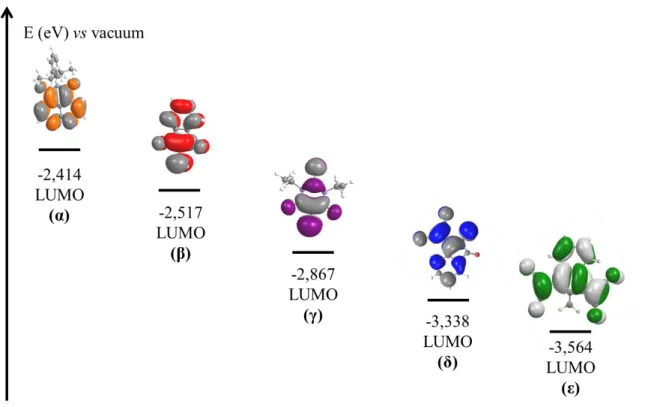
II.A.1.b. Evaluation of the strength of the different acceptors 64 II.A.1.b.i. Study of the chemical formulae of the different acceptors 65 II.A.1.b.ii. LUMO level calculation for the different acceptor groups 66
II.A.1.b.iii. Conclusions 67
II.A.2. Organic synthesis of the bithiophen dyes 67
II.A.2.a. Retro-synthetic scheme 67
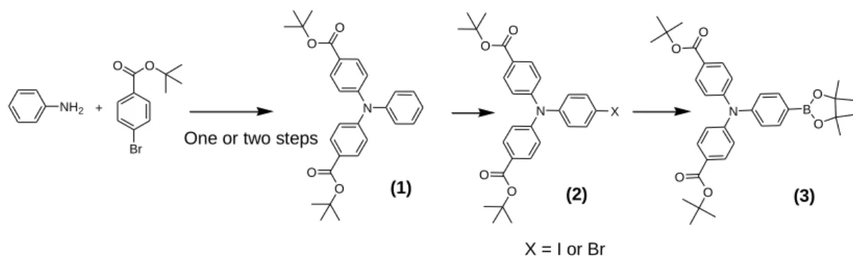
II.A.2.b. Synthesis of the triphenylamine building block 68
II.A.2.b.i. Introduction 68
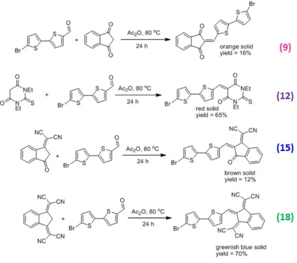
II.A.2.b.ii. State of the art for the synthesis of TPA (3) 68 II.A.2.b.iii. Synthesis of the boronic pinacol-ester triphenylamine (3) 70 II.A.2.c. Synthesis of the 5 acceptor groups (6), (9), (12), (15) and (19) 73 II.A.2.c.i. Synthesis of diisopropylphenyl-naphtalimide-bromobithiophen (6) 73 II.A.2.c.ii. Synthesis of the methylene-derivative acceptors (9), (12) and (15) 75 II.A.2.d. Microwave assisted Suzuki-Miyaura cross coupling of the various acceptors with TPA -
Synthesis of (7), (10), (13), (16) and (19) 75
II.A.2.e. Deprotection with TFA - Synthesis of the final compounds (8), (11), (14), (17) 78
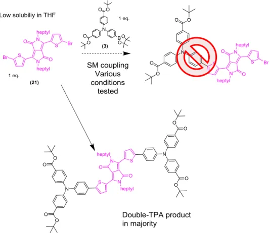
II.A.3. Toward DPP derivatives 78
II.A.3.a. Targeted synthetic pathway 78
II.A.3.b. Synthesis of the dyes with DPP skeleton 79
II.A.4. Conclusions 83
II.B. Physical properties of the synthesized dyes 84
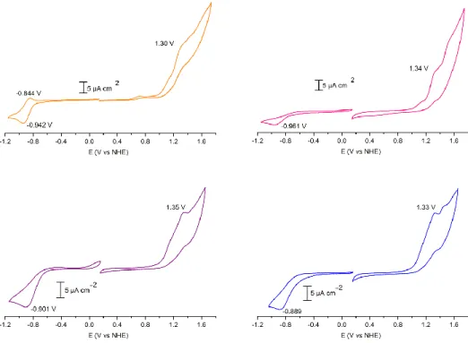
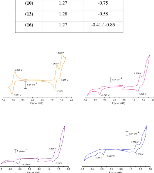
II.B.1. Electrochemical studies 84
II.B.1.a. Electrochemical studies of the dyes in DMF 84
II.B.1.b. Electrochemical work on the tert-butyl ester protected version of the dyes 85
II.B.2. Steady state optical properties 89
II.B.2.a. Steady state UV/Visible absorption spectra 89
II.B.2.b. Steady state emission spectra 92
II.B.3. Summary and conclusion 94
III. NIO FORMATION THROUGH INK-JET PRINTING
99
III.A. The different NiO synthesis techniques 101
III.A.1. NiO prefabricated nanomaterial paste 101
III.A.1.a. General method for the paste preparation 101
III.A.1.b. NiO nanoparticles as the preformed object 102
III.A.1.c. Other prefabricated materials 103
III.A.1.d. Other pastes 104
7
III.A.2.a. The Ni(OH)2 slurry way 105
III.A.2.b. The sol-gel templated way 106
III.A.2.b.i. Templating NiO films with pluronic tribloc copolymers 106 III.A.2.b.ii. Tuning the thickness of the F108 templated NiO films 109
III.A.2.c. Using other templates than pluronic block copolymers 111 III.A.3. Comparison of the different methods and conclusions 113
III.A.3.a. Comparison of the actual “two best NiO” 113
III.A.3.b. Conclusions 115
III.B. Doctor-blading NiO films with F127 as the copolymer block 115
III.B.1. Use of a “Classical” ink 115
III.B.1.a. Preparation of “classical” doctor-bladed NiO film with F127 as the templating agent 115
III.B.1.b. SEM analysis 117
III.B.1.b.i. Thick black zones 117
III.B.1.b.ii. Thin transparent zone 117
III.B.1.c. Possible mechanism for film morphology 120
III.B.1.d. Reproducibility issues 122
III.B.2. Increasing the viscosity of the ink 122
III.B.3. Conclusions 124
III.C. NiO films fabrication through ink-jet printing 124
III.C.1. Introduction 124
III.C.1.a. Generalities- Ink-jet printing for materials applications 124
III.C.1.a.i. An attractive technique 124
III.C.1.a.ii. Industrial challenges 125
III.C.1.b. IJP basic principles and requirement 126
III.C.1.b.i. Continuous IJP and Drop on demand IJP 126
III.C.1.b.ii. The successive steps of IJP 127
III.C.1.b.iii. Ink design and formulation for IJP 129
III.C.1.c. Ink-jet printing oxides via the sol-gel way 129
III.C.1.c.i. State of the art 129
III.C.1.c.ii. Combinatorial material synthesis 130
III.C.1.d. Conclusions 131
III.C.2. Fabrication of NiO films for DSSC through ink-jet printing 131
III.C.2.a. Ink preparation 131
III.C.2.a.i. Ink formulation for IJP 131
III.C.2.a.i.(i) First investigations 131
III.C.2.a.i.(ii) Decreasing the ink viscosity 132
III.C.2.a.i.(iii) Surface tension and contact angle 134
III.C.2.a.ii. Aging of the ink 134
III.C.2.b. Printer description 135
III.C.2.c. Printing parameters for NiO film preparation 135
III.C.2.c.i. First-step required: preparing the cartridge 135
III.C.2.c.ii. Common parameters for all films formation 136
III.C.2.c.iii. First set of parameters (« set-1 ») 136
III.C.2.c.iii.(i) Drop generation 136
III.C.2.c.iii.(ii) Film formation 137
III.C.2.c.iv. Second set of parameters (« set-2 ») 138
III.C.2.c.iv.(i) Drop generation 138
III.C.2.c.iv.(ii) Film formation 139
III.C.2.d. Role of humidity 139
III.C.2.e. Deposition of one layer of NiO substrates (NiO-1L samples) 139
8
III.C.2.e.ii. Film morphology 139
III.C.2.f. Increasing the number of NiO layers 141
III.C.2.f.i. Interlayer drying of 30°C 141
III.C.2.f.ii. Interlayer drying of 100°C 144
III.C.2.f.iii. Interlayer sintering at 450°C 144
III.C.3. Study of NiO formation mechanism 147
III.C.3.a. TGA analysis 147
III.C.3.b. NiO formation mechanism study with XPS 149
III.C.4. Conclusions 153
IV. BUILDING EFFICIENT DSSCS WITH THE NEW DYES AND IJP NIO
161
IV.A. Introduction 163
IV.B. p-Type DSSCs with NiO-1L films, sensitized with dye (8) 163
IV.B.1. Sensitizing the NiO-1L electrodes with dye (8) 163
IV.B.1.a. Solvent choice 163
IV.B.1.b. Dying bath duration 164
IV.B.1.c. Solid state UV/Vis spectra of the sensitized NiO film 165
IV.B.2. p-Type DSSCs tests methodology 167
IV.B.2.a. Fabrication of the DSSC 167
IV.B.2.b. Parameters for the solar cell tests 168
IV.B.3. Results 169
IV.B.4. Conclusion 170
IV.C. p-Type DSSCs performances with thicker NiO films 171
IV.C.1. Solar cell fabrication and test parameters 171
IV.C.2. Dual pore, nanofiber like morphology 171
IV.C.3. Compact nanoparticle morphology: 173
IV.C.3.a. Optical properties 173
IV.C.3.b. Photovoltaic performance 175
IV.D. Introducing a NiOx contact layer between FTO and NiO 177
IV.D.1. NiOx thin layer deposition 177
IV.D.2. Influence of the NiOx sub layer on the p-type DSSC performance 180 IV.E. Performance of the IJP NiO electrodes with other bithiophen dyes 182
IV.E.1. Sensitization of the NiO electrode 182
IV.E.1.a. Solutions preparation 182
IV.E.1.a.i. Dye (14) 182
IV.E.1.a.ii. Dye (11) and (17) 183
IV.E.1.b. Sensitization of NiO 183
IV.E.1.c. Device tests on NiO-4L electrode 185
IV.E.2. Conclusion 188
IV.F. Conclusions 189
9
EXPERIMENTAL PART
195
I. ORGANIC SYNTHESIS (CHAPTER 2, PART I)
197
I.A. General conditions 197
I.B. Synthesis of the different intermediates and final molecules 198
II. PHYSICAL PROPERTIES (CHAPTER 2, PART 2)
226
II.A. Generalities 226
II.B. Electrochemistry 226
II.C. UV-Visible spectra in solution 227
II.D. DFT/TDDFT calculations 228
III. DSSC FABRICATION THROUGH IJP. SOLAR CELL TESTS. (CHAPTER 3
AND CHAPTER 4)
229
III.A. Generalities 229
III.B. DSSC fabrication 229
III.B.1. Cleaning the FTO substrates 229
III.B.2. Preparing the NiOx precursor solution 230
III.B.3. Deposing the NiOx layer 230
III.B.4. Preparation of the NiCl2 diluted ink for printing 230
III.B.5. Preparation of the printer 231
III.B.6. Preparation of the substrates 231
III.B.7. Mesoporous NiO Film deposition 232
III.B.8. Sensitization of the photocathode 233
III.B.8.a. Sensitization solution preparation 233
III.B.8.b. Substrate sensitization 233
III.B.9. Preparation of the Electrolyte 233
III.B.10. Solar cell fabrication 233
III.B.11. Photovoltaic measurements 234
IV. MISCELLANEOUS INFORMATION
235
IV.A. Doctor-bladed films Ink-0 morphology 235
IV.B. Rheological properties 235
IV.C. NiO film thickness measurements 235
IV.D. NiOx thickness measurements 235
IV.E. NiO sensitized film solid-state absorption measurements 235
10
ANNEXES
239
I. ANNEX 1 - ANOTHER PHOTOCATHODE MATERIAL THAN NIO ?
241
I.A. A Cu(II) material, CuO: 241
I.B. Delafossite Cu(I) materials : 241
I.B.1. CuAlO2 242
I.B.2. CuGaO2 243
I.B.3. CuCrO2 243
I.C. ITO material 244
I.D. Other materials 244
I.E. Conclusions 245
II. ANNEX 2 - CHOICE OF THE CATALYTIC SYSTEM FOR SM COUPLING 247
III. ANNEX 3 - DFT/TDDFT RESULTS
250
III.A. Introduction 250 III.B. Results 251 III.B.1. Dye (8) 251 III.B.2. Dye (11) 253 III.B.3. Dye (14) 255 III.B.4. Dye (17) 257
III.C. Various remarks 258
III.D. Modular analysis of the push-pull interaction 259
III.D.1. Modular gap tuning 259
III.D.2. Frontier orbitals coupling 260
III.E. Dipolar moments of the dyes and orientation 264
III.E.1. Dye (8) 264
III.E.2. Dye (11) 264
III.E.3. Dye (14) 265
III.E.4. Dye (17) 265
IV. ANNEX 4 – RED ABSORBING DYES REVIEW
267
V. ANNEX 5 – LIGHT SOAKING EFFECT
269
11
Remerciements
Je remercie toutes les personnes qui ont, de près ou de loin, participé à l’aboutissement de ce projet de thèse, tout particulièrement Tiphaine, « ma cothésarde » pour sa gentillesse et sa grande aide sur tous les aspects. Après deux stages et une thèse au même endroit, nos chemins professionnels se séparent maintenant et je ne doute pas qu’ils se recroiseront.
Je remercie également tout particulièrement Rita Faddoul, Thomas Berthelot et Alexandre Causier pour leur précieuse aide avec l’imprimante jet d’encre, ainsi que Jean-Mauel Raimundo et Praveen Chandrasekar pour avoir synthétisé et fourni de nombreux composés clefs pour ce travail de thèse. Un grand merci à Guillaume Deau (contrat d’apprentissage) pour son aide précieuse en synthèse également et à Laure Pantaleo (stagiaire M2) pour ses manips sur CuSCN. Une pensée particulière va à Stéphane Campidelli pour les clichés MEB magnifiques qu’il a réalisés. Un grand merci à Thomas Gustavsson et Valentin Mafféis pour m’avoir fait découvrir le merveilleux monde de la spectroscopie optique stationnaire et ultrarapide, ces connaissances me seront très utiles pour la suite j’en suis sûr. Merci également à Jocelyne Leroy pour les analyses XPS, sa gentillesse et son aide pour l’interprétation des spectres. Merci à Claire et Cédric pour leurs conseils en chimie organique et pour leur aide sur le banc également. Merci à Renaud pour les quelques relectures et autres avis toujours pertinents. Merci à Vincent Artero et Nicolas Kaeffer pour les quelques échanges que nous avons eus. Merci à Bernard Geffroy et Denis Tondelier pour leur aide à Orgatech et la confiance qu’ils m’ont donnée dans l’utilisation du simulateur solaire. Je remercie vivement Valentina Ivanova pour les nombreux conseils également ainsi que Catherine Jullien, Brigitte Mouanda et Nabila Debou, pour toutes les petites choses de la vie de tous les jours au labo. Merci à Serge Palacin de m’avoir accueilli.
Enfin, je ne remercierai jamais assez Bruno, ce fut un honneur d’être dans ton équipe, très à l’écoute, toujours l’idée qu’il faut pour résoudre un problème, merci de m’avoir fait confiance et donné autant d’autonomie et de liberté, toujours avec le sourire. Sans tout cela, je ne pense pas
12 que j’aurais pris autant de plaisir à travailler. La liste des collègues que je souhaite par ailleurs remercier pour les conseils et surtout la bonne humeur au cours de ces trois années au LICSEN est longue … Mais ils se reconnaitront j’en suis sûr. Je leur dis à bientôt ! Mes amis d’ici ou d’ailleurs (un grand Merci à Amandine et Elise) et ma famille ont également grandement contribué à ce travail, merci à eux. Je dédis cette thèse à mes grands-parents.
13
Introduction
Dye-Sensitized Solar cells (DSSCs), initially developed by the work of Grätzel and O’Regean1 in the early 90’s offer competitive performance. Recently, a high value of 14% photo-conversion yield was obtained for DSSCs, making them really promising as a cost effective alternative to the market-dominating Si-based technology 5. DSSCs are part of the third generation solar cells (comprising organic solar cells 2, perovskite solar cells 3 and quantum dots solar cells 4) which display low cost of fabrication, though effort toward enhanced scalability must be done. DSSCs are generally composed of a photoanode and a cathode, sandwiching an electrolyte. The working principle resembles the one of natural-photosynthesis: a dye molecule absorbs light in the visible range 6, but the solar energy is not stored in chemical bonds and is rather directly converted to electricity.
This thesis focuses on p-type, photocathodic DSSCs. The development of this type of cells is very recent 7 and actually their performance remains far below the one of the “classical”, photoanodic DSSCs, due to several constitutive hurdles. However, such solar-cells are precious to study, regarding the possibilities offered by the Tandem-Dye Densitized Solar Cell (T-DSSC) configuration 8. T-DSSCs actually possess theoretical photo-conversion efficiency that are superior to the “one photo electrode” configuration that is: 40% (T-DSSC) vs 30% (one electrode
classical DSSC) 9. Another aspect is the possibility offered by the p-type photocathodes for hydrogen production, when the dye of the photocathode is associated to HER (Hydrogen Evolution Reaction) catalyst, allowing for direct storage of the Sun Energy into chemical bonds, and allowing thus carbon free hydrogen. Tandem photoelectrochemical cells for water splitting represent a paradigm in that purpose 10.
14 Fabricating efficient p-type DSSCs is a first step toward efficient tandem devices. In that goal, the present work focuses on the synthesis of new sensitizers for NiO based photocathodes and on a new method for NiO fabrication, ink-jet printing.
The first chapter is centered on the working principle of p-type DSSCs, and the issues inherent to this type of solar cell. The actual solutions that were found to increase their performance were reviewed.
The second chapter is dedicated to new push-pull organic dye synthesis and characterization (optical and electrochemical properties).
The third chapter ponders upon, NiO photocathode fabrication, through ink-jet printing. A state of the art, presenting the best NiO preparation method was firstly done. Ink-jet printing technique was described and finally, the NiO photoelectrode preparation with this method was presented. This thesis finishes by the photovoltaic performance of the ink-jet printed films, with the various synthesized dye. The sensitization conditions are discussed, as well as the effect of a new NiOx
sub-layer over the solar cell performances.
1. O’Regan, B. & Grätzel, M. A low-cost, high-efficiency solar cell based on dye-sensitized colloidal TiO2 films. Nature 353, 737–740 (1991).
2. Roncali, J., Leriche, P. & Blanchard, P. Molecular Materials for Organic Photovoltaics: Small is Beautiful. Adv. Mater. 26, 3821–3838 (2014).
3. Li, X. et al. Improved performance and stability of perovskite solar cells by crystal crosslinking with alkylphosphonic acid ω-ammonium chlorides. Nat. Chem. 7, 703–711 (2015).
4. Chuang, C.-H. M., Brown, P. R., Bulović, V. & Bawendi, M. G. Improved performance and stability in quantum dot solar cells through band alignment engineering. Nat. Mater. 13, 796–801 (2014).
5. Kakiage, K. et al. Highly-efficient dye-sensitized solar cells with collaborative sensitization by silyl-anchor and carboxy-silyl-anchor dyes. Chem Commun 51, 15894–15897 (2015).
6. Grätzel, M. The advent of mesoscopic injection solar cells. Prog. Photovolt. Res. Appl. 14, 429–442 (2006).
15 7. He, J., Lindström, H., Hagfeldt, A. & Lindquist, S.-E. Dye-Sensitized Nanostructured p-Type Nickel
Oxide Film as a Photocathode for a Solar Cell. J. Phys. Chem. B 103, 8940–8943 (1999).
8. Nattestad, A. et al. Highly efficient photocathodes for dye-sensitized tandem solar cells. Nat. Mater. 9, 31–35 (2010).
9. Odobel, F. et al. Recent advances and future directions to optimize the performances of p-type dye-sensitized solar cells. Coord. Chem. Rev. 256, 2414–2423 (2012).
10. Li, F. et al. Organic Dye-Sensitized Tandem Photoelectrochemical Cell for Light Driven Total Water Splitting. J. Am. Chem. Soc. 137, 9153–9159 (2015).
17
I. How to build the best
19
I.A. General working principle of a p-type DSSC
I.A.1. Basics
For p-type DSSCs the photo-electrode is the cathode. With such a device, the dye’s light absorption induces a photo-generated electron flux corresponding to a photo-reduction of the electrolyte redox-shuttle. Under irradiation, electrons flow from the photocathode/dye composite material, to the electrolyte. This is the reverse process as for n-type DSSCs.
Except some rare examples, a p-type semi-conductor is employed as the photocathode material and ensures, through hole conduction inside its VB, the desired electron flux toward the electrolyte. In the majority of the case, NiO has often been the p-type material employed and actually, despite several shortcomings, permitted to obtain the best results for p-type DSSCs 1. Some research groups have been trying to replace NiO, essentially with delafossite material 2. However, up to now, no real breakthrough was obtained (this aspect is tackled in Annexe 1). The most employed redox shuttle is still the I3
-/I- redox couple, like for n-type DSSCs. As described later in this thesis, research to replace this redox couple is of paramount importance in the field of p-type DSSCs and leads to some recent breakthroughs by the group of Udo Bach who used cobalt3 and iron1 based electrolytes (see Fig. 1). On the other hand, an important amount of research was dedicated to dye design for NiO based photo-cathodes. A selection of the today’s most efficient dyes have been represented in Figure 2, even if the best one is by far PMI-6T-TPA, developed by Bauërle and Bach 4.
Fig. 1- The actual two best performing redox shuttle for p-type DSSCs, giving records VOC values.
Co NH2 H2 N H2N H2N NH2 N H2 2+/3+ Fe O O O O O O 0/1
-20 PMI-6T-TPA.
PCE = 2.5% (2015, Bach et al., Fe electrolyte). PCE = 0.61% (2012, Bach et al. Iodine based electrolyte)
CAD3, PCE = 0.25% (2015, Gibson et al. Iodine based electrolyte)
PMI-NDI, PCE = 0.20 % (2009, Odobel et al., Co based electrolyte)
QT-1
PCE = 0.33% (2015, Zhang et al., Iodine based electrolyte) PCE = 0.50% (2015, Zhang et al, Co based electrolyte)
Fig. 2- A selection of today’s best dyes employed for NiO sensitization alongside with their efficiency under 1 Sun irradiation (AM 1.5). N O HO O OH S N O O 6 O OH N S N C6H13 Br S N C6H13 Br N N O O O O Octyl N O O HO O O O O N O HO O HO S CN CN
21
I.A.2. The successive steps for photocurrent generation
A simplified and summarizing working principle scheme of a NiO based p-type DSSC is depicted on Fig. 3. The first step is the dye excitation with sunlight, which comes from the cathode side (1). Hole injection (2) is the second phenomenon to happen, rather than redox-shuttle reduction, a charged separated state is thus formed (NiO(+)-Dye(-)) 5. The role of the redox shuttle is to oxidize the as-formed reduced dye, this is called the dye regeneration process (3). The injected hole is transported to FTO, via the mesoporous network of the p-type semi-conducting oxide (4). Finally, the external circuit permits to regenerate the redox shuttle at the counter electrode by electron transfer from the redox shuttle (which ensured charge transport by diffusion) to the counter electrode, which is generally made of platinum.
I.A.3. Typical J-V characteristics for p-type DSSCs
A typical J-V curve for p-type DSSCs is shown on Fig. 4. The important parameters for such a curve are indicated: short-circuit current (JSC), open-circuit potential (VOC) and Fill-Factor (FF).
The PCE yield is the power generated at the maximum power point of the curve, divided by the light power input used to irradiate the solar cell (Pincident).
22 For p-type DSSCs, the JSC values now reach 8 mA.cm
-2
for some few examples 6,7. However, in general, the values for what are considered to be efficient photocathodes are between 2 and 5 mA.cm-2 8,9. VOC values with iodine-based electrolyte are generally low and around 100 mV
10,11,12
with few examples displaying values around 120/150 mV 9,13,14,15,16 and one example displaying a high VOC of 294 mV
17
(with PMI-6T-TPA as dye). As represented on Fig. 4, a low FF value (at best 40%) is the main issue for p-type DSSCs, as detailed further. This all turns that the performance of p-type DSSCs are still low and their PCE are far below the ones for n-type DSSCs.
I.A.4. Energetic requirements
In order to ensure the photovoltaic effect to happen, there are some energetic requirements to be satisfied for the components of a p-type DSSC. First of all: the dye’s HOMO must be below the semi-conductor’s valence band (VB) edge, in order to provide enough driving force for hole
Fig. 4- Typical J-V characteristics for a p-type DSSC. Pmax is the maximum power that can be generated by the solar cell under illumination and corresponds to A1, the area of the red rectangle (defined by a voltage:VPmax and a current density: JPmax). A2, the area of the orange rectangle, defines the theoretical maximum power that could be delivered if there were no loss.
23 injection. Secondly, the dye’s LUMO must lie above the Nernstian redox potential of the redox couple implied in the regeneration reaction, in order to provide sufficient driving force for dye regeneration. The VB edge value used for NiO is generally + 0.53 V vs NHE (or - 5.13 eV vs vacuum, NHE was taken at -4. 6V with respect to the vacuum level 18) and the redox potential of the couple implicated in dye regeneration for iodine based electrolyte, {I3
-/I2•-, I
-} is -0.18 V vs NHE 19.
The question of the limit value for hole injection driving force is tackled later in this chapter (see I.B.3.c), but recent works anyway suggest that hole injection driving force should be substantial, if one wants the device to work properly at positive bias 20.
For dye regeneration driving force, one can think of the very efficient dye, CDA3 (see Fig. 2).
This dye, with only a 170 mV driving force for dye regeneration 8, generated a JSC of
8.21 mA.cm- 2. On the other hand the dye PMI-NDI, developed by the group of Fabrice Odobel, shows limited photocurrent values with iodine based electrolytes (1.76 mA.cm-2) attributed to a weak regeneration driving force (~80 mV).
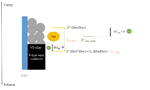
Importantly, another way to consider energetic issues in a p-type DSSC, as detailed on Fig. 5, is to take in consideration that the first step following dye excitation is the hole injection into NiO valence band 21. Then, for hole injection driving force calculation, one should consider the excited dye reduction potential. This potential is “E°(Dye*/Dye-)” on Fig. 5 and is used to be calculated by adding to the ground state dye’s reduction potential “E°(Dye/Dye-)”, the energy stored during
dye excitation22:“E0-0”. This formula is in acquaintance with the fact that when excited a dye
molecule is more easily reduced compared to ground state. Based on this, the driving force for hole injection (ΔGinj) is then calculated as the difference of the dye’s excited reduction potential
and the semi-conductor VB edge. On the other hand, the driving force for dye regeneration (ΔGreg) is the difference between the ground-state oxidation potential of the reduced form of the
24
I.A.5. The kinetic problems of p-type DSSCs
On paper, suitable energetic design should permit to have efficient devices, like for TiO2 based
DSSCs. However, one of the main issues for p-type DSSCs is the unfavourable recombination reactions. As one can see on Fig. 6, there are three reactions preventing electrons to flow in the desired way, which then represent three different recombination pathways.
Fig. 6- The different charge recombination pathways for p-type DSSCs Fig. 5- Energetics of a p-type DSSC (simplified scheme).
25 The first one is called the geminate pathway, and represents recombination between the reduced dye and the injected holes in NiO. The second one relates to the recombination between injected holes in the NiO and the reducing species in the electrolyte. This recombination pathway can happen everywhere in the NiO film, especially for NiO thick film, it is possible that this recombination pathway prevents the hole to reach efficiently the FTO electrode (or I- ions to get out of the NiO film, as the diffusion current of that species should also be taken into account). The third recombination path, maybe less described for p-type DSSCs, but recently pointed out to have dramatic influence on the cell performance when using an iron complex as a redox shuttle1, is the recombination at the FTO/electrolyte interface. Fighting against those 3 recombination pathways is very important if one wants to increase the fill factor of these cells, as recombination arises at low bias for NiO based p-type DSSCs.
I.A.6. VOC engeenering
An important issue for p-type DSSCs is the maximum photo-voltage that can be generated by the solar cell, in test conditions (generally, 1 Sun irradiation, with the AM 1.5 standard). This maximum photo-voltage is generated when the current is equal to zero on the J-V curve, i.e. in open-circuit conditions. This voltage is the VOC. As said above, VOC of p-type DSSCs are still low
despite recent breakthroughs.
In order to better understand VOC, a “thought” experiment corresponding to VOC generation is
depicted in Fig. 7. For sake of simplicity, a p-type DSSC for which the counter electrode is connected to mass reference electrode was considered. This allows considering the Fermi level of the counter electrode and the electrolyte as fixed. In order to signify the open-circuit condition, an open switch was placed between the two electrodes.
Prior to irradiation, the Fermi-level of the electrolyte and the one of the photo-cathode are aligned (since the equilibrium is supposed to be reached), the hypothesis of band bending inside the particle 23 was not taken into account on this scheme. After light irradiation, hole injection occurs into NiO. This is why the Fermi level in NiO goes down in energy, close to the VB edge. This creates a positive photo-voltage. However, this situation corresponds to an “ideal” situation. In
26 fact, some of the holes injected into NiO recombine (see I.A.5 for the different types of recombination). Then, as the hole concentration in NiO is reduced, the NiO Fermi level “goes up” in energy, the “ideal” photo-voltage is reduced.
As shown on Fig. 7, when iodine electrolyte is employed with NiO, the ideal VOC is low, due to
the small energy difference between NiO VB edge and the Fermi level of the iodine electrolyte (approximately 200 mV). So, to increase VOC, one can first consider to decrease NiO VB edge.
This strategy has been adopted by doping NiO with other transition metals and permitted to slightly increase VOC (by less than 60 mV)
24,25,23
. Another strategy is to employ redox couples with a redox potential more negative than for I3
-/I-, which results in moving up-ward the Fermi level of the electrolyte. Based on these ideas, Udo Bach and Leone Spiccia actually implemented two new efficient redox shuttles, with dramatically more negative redox potentials than iodine electrolytes. The first one, [CoII/III(ena)3] (see Fig. 1), EFermi = -0.05 V vs NHE, in ACN) permitted
to reach VOC values as high as 709 mV 3
and the second one, [FeII/III(acac)3] (see Fig. 1, EFermi =
-0.2 V vs NHE, in ACN) permitted to reach VOC = 645 mV.
The second strategy to increase VOC is to fight against charge recombination, in order to keep the
Fermi level under open circuit conditions as close as possible to the VB edge of NiO and to permit that VOC is close to its “ideal” value, as described in Fig. 7. An important example on this
topic is the cobaltII/III electrolyte employed by Gibson et al.26. Any phenomenon that can slow down charge recombination may actually increase VOC.
27
Fig. 7- “Thought” experiment for the generation of a photovoltage under illumination for p-type DSSCs. The situation in the dark is taken as a starting point (top). An ideal situation, under illumination is depicted in the middle. The real situation is depicted at the bottom. The electrolyte considered here is the “classical” iodine electrolyte: 0,1M I2 / 1M LiI in acetonitrile.
28
I.B. How to build the best p-type DSSCs with NiO?
I.B.1. Introduction
Thanks to an increasing number of publications dealing with p-type DSSCs, it is possible to draw a cartography on how to improve each step, in the working principle of a NiO based p-type DSSC. This chapter is divided into sections, which actually describe how each of these steps was improved up to now.
I.B.2. Increasing the light harvesting properties of the film
I.B.2.a. Introduction, the dye/NiO light absorption competition Increasing the light harvesting properties of the {NiO / dye} film can be summarized by improving the following aspects:
Dye molar extinction coefficient Dye absorption spectral window width Dye loading at the NiO surface
The specific surface area of NiO per volume unit of film and its accessibility by the dye molecule, during the sensitization step (suitable pore size)
The thickness of the NiO film
However, one also has to take into account an issue for NiO use as a photocathode material: its important self-absorption. For instance a 1µm-thick, undyed NiO film, as described by the group of Bach, already absorbs 30% to 40% of the incident light 4. That means that a 4µm-thick bare NiO film would absorb 85% of light. This issue is a major one and makes the use of thick NiO films simply impossible, contrary to TiO2, which is more transparent. The NiO self-absorption is
not known to allow high photocurrent generation, as naked NiO mesoporous electrode have very poor performance 27. This is why NiO self-absorption is detrimental for device performance. In order to reduce this effect, one can consider the following possibilities:
Increasing the porosity of the film (meaning that less NiO is present in a given film volume) Decreasing the number of defects of the NiO material (as NiO parasitic absorption comes from the presence of defects in the material, as said below)
29 So as to give a clear picture of the competition between dye light absorption and NiO light absorption, one can resort to the ratio between dye absorbance and NiO absorbance, as described by the group of Bach 28 (eq. 1). This absorption ratio should be maximal for better light harvesting properties of the photocathode. Another aspect that should also be mentioned is the parasitic absorption of the electrolyte employed, since for instance the classical iodine based electrolyte absorbs at low wavelengths a substantial amount of light 27.
I.B.2.b. NiO engineering for enhanced light harvesting properties of the film
I.B.2.b.i. NiO parasitic light absorption
NiO is a wide band-gap p-type semi-conductor (3.4 to 4.6 eV 29), which should then provide good transparency in the visible region and be very suitable for p-type DSSC application. Then, where does the self-absorption of NiO come from?
In order to understand the reasons for NiO coloration, one should think of the origin of the p-type conductivity of this material. For NiO, p-type conductivity comes from the fact that it is a non-stoichiometric material, with oxygen excess 30. To compensate for the oxygen richness, defect species as Ni3+ species (which could be Ni2O3 or NiOOH
31
), or even Ni4+ species 32 exist in NiO material. In a way, hydrogen atom may also compensate the oxygen excess, through the creation of species such as NiII(OH)2. One can understand that the creation of Ni
3+
species correspond to the creation of holes in the VB of NiO and then corresponds to a doping process. This actually stands for an explanation for NiO p-type conductivity. However, if the p-type conductivity is ensured by the defect species, Boschloo and Hagfeldt stated that Ni3+ species have a strong black coloration compared to Ni2+, due to enhanced d-d transitions (Ni2+ has the d8 configuration). This mechanism for NiO self-absorption is the one most often presented 33 and actually meets well with the electrochromic behavior of NiO, which is described below. Interestingly, one should notice that another self-absorption mechanism, coming from the possible presence of Ni metal defects in the film has also been accurately reported 34.
Absorbance ratio (Dye:NiO) (λ) = Adye (λ) / ANiO(λ)
30 As a matter of fact, depending on the potential that is applied to NiO, its color is different: as said above, NiO is an electrochromic material. When its Fermi level lies far in NiO band-gap, there is almost no hole in the VB, this is the bleaching situation. When the Fermi level is pushed toward more positive potentials the number of holes increases and the coloration of NiO as well. The holes that are present display brown coloration first and then black coloration. As suggested by Hagfeldt and Boschloo, two different absorbing species may be formed when increasing the Fermi level to positive potentials. The first one is supposed to be Ni3+ species. The second one seems to be less understood, though a recent study by Dini and coworkers speaks for the presence of Ni4+ species 32. For both species, the absorption peaks ranges between 350 nm and 550 nm and also extends to the NIR region (see Fig. 8 for the overall feature of NiO absorbance). At rest, that is, when not in contact with electrolyte, nor biased, the Fermi level of NiO is close to its VB edge and then NiO displays a substantial coloration.
This electrochromic behaviour, induces competition between NiO and dye absorption and is then a limit for NiO use at positive bias, as pointed out and proven by the group of Bach, who estimated the efficiency loss to be about 5% for a device with a CoII/III(en)3 based electrolyte
20
.
Fig. 8- Taken from the ref. by Hagfeldt and Boschloo. Potential-dependent optical spectra of nanostructure NiO, in presence of an aqueous electrolyte, from 0.310 to 1.110 V vs NHE, by step of 0.10 V. The bleach state at 0.01V vs NHE has been subtracted. The spectral features were described to be independent of the NiO environment. 0 (electrolyte etc.). The value of + 0.210 was used for converting the value vs {AgAgCl, 3M} to NHE reference.
31 I.B.2.b.ii. Engineering NiO for more efficient light harvesting properties
There are actually a few examples dedicated to enhancing NiO optical properties. The important point, as said above, is to increase the dye/NiO absorbance ratio. Bach et al. increased the NiO crystallinity of the NiO nanoparticles (see chapter 3 for more details) without decreasing dye up-take, and a better NiO transparency was invoked 17. The same group also reported an original NiO microball morphology. The films made out of these microballs presented an increased Dye/NiO absorption ratio and this permitted to reach high JSC value (i.e. 7 mA.cm
-2
, for a 6 µm substrate). The increase was attributed to a better crystallinity of NiO or a more important specific surface. The group of Li also suggested that the morphology of NiO could induce a more important dye loading in some cases 16 (see chapter 3 for more details). Another point, also exemplified by the group of Bach showed that a more crystalline NiO material also induced more light diffusion inside the NiO film and then increased the light pathway, and this was reported to be beneficial for the solar cell performance 17.
I.B.2.c. Dye engineering for enhancing the light harvesting properties of the NiO film
I.B.2.c.i. The tool-box for light transitions
This paragraph is the occasion to detail two types of light absorption transitions that have been exploited for dye design for p-type DSSCs up to now. We chose to separate these transitions considering the electron movement following light absorption, once the dye is grafted onto the NiO surface. Electron movement at the NiO surface may be important to understand in p-type DSSCs in order to better understand recombination / hole injection kinetics.
The first type of transition can be called a “localized transition”, light absorption does not induce particular electron movement regarding the NiO surface (we include MLCT transitions for Ru-based dyes for instance, here). The second one is the push-pull transition, it is a specific transition, which corresponds the mixing of the orbitals of different chromophores in the molecule, a donor and an acceptor. It gives rise to a new transition and then an electron movement from the donor-part to the acceptor donor-part following light absorption (details are given in Annex. 3).
32 I.B.2.c.i.(i) “Localized” transition
Some chromophores, corresponding to a “localized” light absorption transition have been known by the chemists for a long time and have thus been employed as sensitizers for p-type DSSCs. Among them, one can refer to two categories: the purely organic dyes, and the metal-organic dyes. The first one being preferable in order to avoid resorting to expensive and sometimes scarce metals. Among purely organic dyes, one can consider the following: coumarin35, squaraine 36,37, perylene monoimide derivatives 4,14,15, perylene di-imide 38, sexithiophen 4, diketopyrrolopyrole 13, cyanine derivatives 35, « fast-green » dye 35 or bodipy 39. For the metal-organic counterpart, one can refer to the use of: zinc porphyrins 40,41, metaloporphycenes 42 and finally ruthenium dyes
11,43,44,45,46
.
I.B.2.c.i.(ii) Push-pull transition
Another way to generate light transition for conjugated molecules is to resort to “push-pull” type transitions. This type of light transition is different compared to the one described above since it induces a direct spatial movement of electrons from a donor (electron-rich) to an acceptor (electron poor) site, upon absorption. It requires an at least non-zero degree of mixing between the two Pi-conjugated entities so as to permit the movement of electrons from one entity to another. For NiO based photocathodes, up to now, the vast majority of push-pull dyes that were used are triphenyl-amine based, for the electron donor group. Several different acceptors have been employed in association with the triphenylamine donor group: malonitrile groups (and the famous P1) 10, 7,13,47,48, tricyano group 10, bodipy 6, indolium 6,8, (N,N)diethyl-thiobarbituric acid 10, 49,47 , DCANQ 50, TCF 50, PMI 9, iso-indigo51, and Ru derivatives 12.
I.B.2.c.ii. Mixing the transitions
Some dyes light absorption is only based on “localized” transitions, by the use of distinct chromophores (such as PMI-NDI, see on Fig. 9), other display a major transition which is a push-pull transition (like P1, see Fig. 9). Finally, other dyes mix the push-push-pull and the “localized” transitions, like for instance the Ru dyes of Wu et al. 11 (dye O18 was exemplified on Fig. 9). The working mechanism of a dye depends on the degree of coupling between the different parts of the
33 dye. For light absorption (especially the push-pull transitions), the working mechanism can be clarified by simulating the absorption spectrum of the dye with TD-DFT calculation.
I.B.2.c.iii. Enhancing dye light absorption
I.B.2.c.iii.(i) Resorting to highly absorbing dyes
A recent example of dye engineering, for enhanced optical properties of the NiO film, has been shown by Gibson et al 6. They presented a series of dyes belonging to the same family (the “push-pull, double acceptor” family, see above) with increasing molar absorption coefficient (see Tab. 1). The increase in the dye molar exctinction coefficient was directly linked to the generation of high JSC, stressing the importance of strongly absorbing dyes for highly efficient devices.
What is then the best strategy to enhance the dye molar extinction coefficient ? If one considers using localized transition dyes, the strategy resides in employing strongly absorbing entities. This
Tab. 1- The dyes series described by Gibson et coll 5, increasing molar extinction coefficient for a dye family so as to increase JSC.
Dye ελmax (mol-1.L.cm-1) JSC (mA.cm-2)
P1 57 900 5.37
GS1 65 700 5.87
CAD3 94 580 8.21
Fig. 9- An example of “localized” transition dye: PMI-NDI, an example of a push-pull type dye (the first one to be used for p-type DSSCs: P1) and an example of a dye combining both types of transitions
34 strategy was succesfull for squaraine dyes for instance, synthesized by the taiwanese Lin et al.37, and successfully implemented into efficient p-type DSSC.
If one considers push-pull type dyes, one can first of all say that the push-pull transitions are generally allowed ones and then exhibit high molar extinction coefficients 5. However, for push-pull dyes in p-type DSSCs, structure-property relationship for dye’s molar extinction coefficients are scarcely established. However, a possibility that showed very efficient is the “double acceptor strategy” so as to increase dye molar extinction coefficient. It is for instance striking to remark that the double acceptor dye CAD3 dye absorbs 4 times more light than CAD1, its monosubsituted version and reaches an impressive value close to 100 000 mol-1.cm-1.L for ε (see Fig. 10). On Fig. 9, P1 dye 52 (sometimes called “dye S” 47) and its monoacceptor analogous, “dye 4” were also represented and for the sake of comparison, the described performance were all taken from the same reference (ref 47). The performance of the double acceptor dye P1 are again better than the one of the mono acceptor compound, owing to an almost doubled molar extinction coefficient. If the double acceptor strategy permits to enhance dye light absorption, one can also mention than there exists mono acceptor compounds that are also strongly absorbing, as examplified by Yen et al. and their “dye 6” 47
. The performance of these dyes in p-type DSSC are good too (see Fig. 9).
35
Fig. 10- The double acceptor strategy and the mono-acceptor strategy for push-pull dye design. The NiO used for CAD dyes is different from the one for the other dyes, which explains the performance difference between the dyes and the different dye loadings.
Dye S » or P1 ελmax = 67 500 mol-1L.cm-1. PCE = 0.101% JSC = 2.31 mA.cm-2
Dye loading = 129 nmol.cm-2
N O H O S S N C NC N C N C
« Dye 4 » ελmax = 34 500 mol-1L.cm-1
PCE = 0.093% JSC = 2.25 mA.cm-2
Dye loading = 130 nmol.cm-2
N O OH O HO S CN NC « CAD1 » ελmax = 22 900 mol-1L.cm-1 PCE = 0.09% JSC = 3.32 mA.cm-2
Dye loading = 6.7µmol.cm-2
O OH N S N C6H13 Br « CAD3 » ελmax = 94 580 mol-1L.cm-1 PCE = 0.25% JSC = 8.21 mA.cm-2
Dye loading = 7.36 µmol.cm-2
O HO N S N C6H13 Br S N C6H13 Br « dye 6 » ελmax = 67 600 mol-1L.cm-1 PCE = 0.087% JSC = 2.05 mA.cm -2
Dye loading = 108 nmol.cm-2
N O OH O HO S S CN NC
36 I.B.2.c.iii.(ii) Resorting to dyes with wide absoprtion window
Some compounds naturally possess a large absorption window, such as Ru derivatives (these compounds bear the advantage of possessing several transitions). For instance, the “simple” Ru derivative so called “O12” and developed by the group of Wu, possess an absorption window between 300 nm and about 580 nm, with a reasonable molar extinction coefficient value around 15000 mol-1L.cm-145, quite constant over this range,. The same group interestingly enhanced their Ru based compound light harvesting properties by using modified ligands, which lead to the formation a “panchromatic dye” O18 (see Fig. 9) 11
. The absorption window of this dye was comprised between 650 nm and 350 nm, with a constant ε value around 30 000 mol-1.L.cm-1). Another example illustrating how to increase the width of the spectral absorption could be the example of the two bodipy dyes employed by Gibson et al. The first bodipy dye exhibits a narrow spectral absorption window, due to the conjugation break between the bodipy entity and the triphenylamine group 39. When permitting the conjugation between the two entities, the spectral width was increased as in dye GS16.
So as to even more increase the amount of light absorbed per molecule, and to cover a wide range of absorption wavelengths, combination of such chromophores can be employed, in a so called « multichromophoric » approach, such as the one described by Odobel et al. with squaraine-perylene monoimide (squaraine-perylene mono-imide, PMI) derivatives 36. In this case, the shape of the absorption spectrum is very close to the sum of each chromophore. Due to the increase in the absorption window, the dye is quite efficient (JSC = 2.73 mA.cm
-2
), though there is a competition between internal de-excitation and hole injection with NiO, possibly because the squaraine and the PMI units are not totally decoupled. Interestingly, the energy transfer phenomenon from the high energy chromophore unit (PMI) to the low energy chromophore unit (squaraine) was not observed.
37 The famous triphenylamine-sexithiophen-perylenemonoimide (PMI-6T-TPA), synthesized by the group of Peter Bauërle 4 is a two distinct chromophore dye. Though this dye is often presented as a “push-pull” sensitizer, it looks more as double chromophore, “dyad”, for which the first chromophore is the (triphenylamine)-sexythiophen group and the perylene-monoimide plays the double role of second chromophore and secondary electron acceptor, judging by its HOMO/LUMO orbitals that are decoupled 4. This molecule is a strong absorber over a wide region of the spectrum (from 300 to 550 nm), due to the association of the two strongly absorbing entities: sexithiophen (ε =50 000 mol-1.L.cm-1 at about 475 nm 53) and PMI (ε = 45 000 mol-1.L.cm-1 at about 550 nm 53). However, the exact “working principle” of PMI-6T-TPA, like for PMI-SQ-NDI dye is actually not published. Eventually, an interesting example which permitted to extend the window absorbed with one photo-electrode has been sensitize NiO with two complementary dyes in terms of absorption, by Chang et al 37. Unfortunately, this strategy did not bring real improvements.
I.B.2.c.iv. Increasing the number of dyes grafted at the NiO surface
A possible strategy to graft more dyes at the surface of NiO can be to place two anchoring groups on the sensitizer. This strategy was actually adopted by Lin et al., with a study of the squaraine dyes, p-SQ1 and p-SQ2 37. The dye p-SQ2 possessed two anchoring carboxylic acid groups and its dye loading was actually multiplied by two compared to p-SQ1 which only possessed one carboxylic acid anchoring group. However, the “two anchoring group strategy for better dye loading” is actually not always valid, as for the two dyes “3” and “5” synthesized by the same
N O HO HO O N N O O N N O O O O C6H17 O O C6H17 C6H17
38 group 47, the two anchoring groups induced a less important dye loading. However, in both cases, it was noted that the compounds with two anchoring groups performed better once implemented into the p-type DSSC.
Similarly, in the same paper, the double acceptor dye P1 (or “dye S”), with only one anchoring group, was compared to its mono-acceptor, two anchoring group, version, so called “dye 4”. Actually, similar levels of dye grafting were obtained for both dyes (see Fig. 10).
As a conclusion, one can say that when it is possible to have two anchoring groups on the molecule, this strategy permits to obtain better performances, but not necessarily a better dye loading (then the better performance may come from a better hole injection process). On the other hand, for the dyes for which only one anchoring group is possible, like for the triphenylamine double acceptor dyes, good performance in p-type DSSCs are obtained too, certainly owing to an increased molar extinction coefficient.
For dye loading, another important point seems to be the overall size of the dye. As shown by a recent paper by Wu et al. when the size of the dye is too important, like for their double PMI-6T-TPA dye, dye loading is reduced, due to steric issues for dye grafting at the NiO surface 15. Interestingly also, in order to increase dye loading at the NiO surface, it seems that the strategy to employ flat and small dyes is an interesting option. This is suggested by the recent work of Zhou et al., who employed QT1 as a very flat, very small and very efficient dye 7.
One can finally add that it should be possible to play trigger the dye loading by palying with the time and the solvent during the sensitization step, as suggested by the very recent work by Zhu et al. 49,b. However, drawing general conclusions about the dye loading is not easy since the thickness of NiO is not always mentioned in the papers and only the geometric dye concentration (obtained by the help of dye desorption experiment) is mentioned . The amount of dye per volume unit of NiO film should be more suitable for comparison between publications. Also, if a high dye loading is important so as to increase the optical properties of the photo-electrode, one should
b Besides, this aspect seems to be a key point in a parallel field of research, when co-grafting species at the
39 mention that dye aggregation, has to be avoided and is sometimes presented to be detrimental for the photocathode efficiency 13.
I.B.2.d. Reducing the electrolyte absorbance
It is known that the currently most used electrolytes, with iodine, highly absorb light between 350 and 450 nm and then can compete at short wavelengths with dye light absorption (a spectrum is displayed in the SI of ref 4). Even if the NiO films employed up to now have been quite thin (1 to 2 µm), this effect must be taken into account if one considers the tandem DSSCs application. In this case, for one photo-electrode, light has to cross at least 25µm of electrolyte. Here dye design is important if one wants to consider this issue. Changing the electrolyte, to a more transparent one is another, more simple option, as shown by Powar et al.3, when comparing iodine based electrolyte and the famous [Co2+/3+(en)3] based electrolyte, which absorbance is dramatically
reduced.
I.B.3. Efficiently inject holes into NiO VB
I.B.3.a. Position of the NiO VB edge
For hole injection from the dye to NiO, the position of NiO VB edge is of paramount importance. Actually, the VB edge position of NiO has been estimated by spectro-electrochemistry, in absence of redox species in the electrolyte. Such studies rely on the optical signature of the holes in NiO VB. When the Fermi level gets close enough to the NiO VB edge, hole absorption is detected and this permits to determine NiO VB edge. In presence of an aqueous electrolyte at pH 6.8, NiO VB was estimated to be ca. 0.2 vs {Ag/AgCl/3M in KCl}, that is 0.410 vs NHE 55. Similar studies were performed in the most used organic solvent: acetonitrile 26,19. Also, the studies were performed in presence of a LiClO4 salt, probably to take into account the possible VB edge
positive shift induced by Li+ cations 26, which are almost always present in p-type DSSCs’ electrolyte c. In this latter case, the VB edge was found to be at -0.12 V vs Fc+/Fc, i.e.
c This effect of the Li+ cations to shift the NiO VB was proven to occur, in a recent publication by the group
of Hammarström et al.24. Besides, another possible effect going in this direction could be the one of the additives employed in the iodine based electrolyte by the group of Udo Bach 4 (use of tert-butyl pyridine and guanidinium thiocyanate). For the famous [Co2+/3+(en)3] electrolyte, the large amount of ethylene
diamine present in the electrolyte is also thought to play a role of NiO band shifting to positive potentials, due to the acidity of the protons it bears 3.
40 approximately 0.53 V vs NHE d,e. The group of Bach also reported the value of 0.7 V vs NHE for NiO ionization potential 56. The value of 0.53 V vs NHE for NiO VB edge is the value used through all this PhD thesis, because it is the most used value in literature.
I.B.3.b. An ultra-rapid and efficient hole injection
As exemplified in early works on phosphorus porphyrins by Odobel et al.57, and confirmed by an important number of publications by the groups of Wu 45,11,58 Hammarström59,14,60 Dietzek 61 and Sun 10, hole injection into NiO VB is the next step after dye excitation, is extremely rapid and then can efficiently compete with the dye return to the ground state. For this reason, hole injection is generally presented as being “not an issue” for p-type DSSCs.
In a primary approach it is interesting to remark that it seems that hole injection driving force does not need to be too important to permit an efficient hole injection process. As an example, one can consider the ruthenium dyes developed by the Wu group 45, for which the excited state reduction potential lies very close to the NiO VBE (hole injection driving force close to zero). Despite that, extremely rapid hole injection was noticed with these compounds. For the other dyes, for which transient absorption studies permitted to conclude that hole injection was efficient, the values for hole injection driving force vary. Values around 300 eV were reported for the simple squaraine dye (“SQ”) developed by Odobel 36
. For push-pull triphenylamine based dyes, hole injection driving force values are generally higher and above 600 mV, due to the interaction between the acceptor and the triphenylamine dye. These interactions slightly depopulate the triphenylamine, which is then harder to oxidize. Finally, for perylene-imide dyes, values around 700 to 800 mV can be calculated 14.
An exception is the multi-chromophoric dye implemented by Odobel et al. in 2013. Indeed, the working principle of this dye is very different than for other dyes. In this case, hole injection was found to compete with hole/electron recombination internal to the dye 36. Recently also,
d
See chapter 2 for the potential values conversion.
e Interestingly, another photo-electrochemical study, by the group of Bach suggests a VB edge at about 0.25
vs the “electrolyte” potential. The electrolyte is composed of cobalt species in ACN, with Li+ cations in the
form of LiTFSI. The Fermi level of this electrolyte has been estimated to be at -0.025 V vs NHE. This turns out the VB edge at about 0.25/0.30 V vs NHE, which is different from the value found by Gibson et all. in ref 19. However, here, the electrolyte contains redox species and also the “additives” are different, then the values are not really comparable.
41 Bräutigam et al. showed that for a Ru dye, it was important to have withdrawing groups on the ligand for efficient hole injection61. Another exception is the bodipy dye described by Gibson et al.39, for which hole injection was not efficient and as the injection rate was estimated to be around 50%. This was certainly due to the decoupling of the absorbing bodipy entity with NiO, due to the conjugation break and the too important tunneling distance between the light absorption center and NiO.
On this point one should remark that a tunneling mechanism for hole injection between the dye HOMO and NiO is a possible efficient mechanism. The very efficient dye PMI-6T-TPA4 and the efficient SQ137 also appear to function with a tunneling mechanism for hole injection, judging by the shape of their simulated HOMO orbitals. On this aspect, it is obvious that “Non-tunneling” mechanisms also permit extremely rapid hole injection, like for the push-pull dye P3 10. The Ru based dye by the group of Wu, O12, is one of the dyes for which hole injection occurs by
tunneling. This dye displayed an extremely rapid hole injection constant, faster than 180 fs f. I.B.3.c. Is hole injection really so un-problematic ?
Recent studies with the dye PMI-6T-TPA, which has relatively small hole injection driving force (400mV) and for which tunneling is the mechanism for hole transfer from the dye to NiO, showed that hole injection could actually be a real issue for the actual best performing dye. Transient absorption studies were performed on NiO films dyed with PMI-6T-TPA, with the nanosecond time scale for a limit. Contrary to previous studies, the key point was that this time, the potential of the studied sensitized electrodes was also varied during the transient absorption studies.
42 It was observed that when the Fermi level of the NiO/dye electrode was moved to positive values of potential, the initial amplitude of the Transient Absorption Signal of the charge separated state of the dye on NiO signal was reduced (see Fig. 12). This was attributed to a less efficient hole injection process, itself attributed to the lower driving force for hole injection for PMI-6T-TPA, which HOMO lies quite close to NiO VB, and the low degree of coupling between this dye HOMO and the electronic states of NiO. For this, the authors indicated that compounds with higher driving force for hole injection should be employed for the next generation of dyes for p-type DSSCs. If one considers the assumptions by the group of Udo Bach, high holes injection driving force, though representing an important energy loss, might be necessary for the solar cell to work at higher positive potentials. This could be an advantage of the push-pull, triphenyl-amine based dyes, compared with PMI-6T-TPA for instance.
Another aspect concerning the efficiency of hole injection and especially the coupling between dye HOMO and NiO is the dye’s anchoring group used in p-type DSSCs. Indeed, the vast majority of the dyes for p-type DSSCs resort to carboxylic acid groups. As they are electro-poor substituents, better anchoring groups could be employed, so as not to represent a barrier for hole
Fig. 12- Reproduced from the publication by Bach and coworkers. Bias dependent transient absorption decay, measured at 850 nm (signal of the charge separated state), using an inert electrolyte. From 0mV (red) to 750 mV (dark green), voltage is reported vs the electrolyte Fermi level (Co(en)3 electrolyte). One can see that the red trace initial amplitude is more important at 0V than at 750 mV, indicating a less efficient hole injection when increasing the bias of the cell.
43 injection. Few investigations have actually been performed concerning other anchoring groups, such as acac groups 74, or pyridine rings 63,64,g.
I.B.4. Fighting against charge recombination
Once the hole has been injected into NiO VB, the main issue is to fight against charge recombination, in order that photocurrent / photo-voltage generation happens.
I.B.4.a. What is known about charge recombination today I.B.4.a.i. The EIS results by the goup of Wu
In 2012, the group of Wu performed an Electrochemical Impedance Study on a 1.5µm NiO substrate, sensitized with the push-pull dye O2 (see Fig. 13), in presence of an iodine electrolyte
65
. They studied the recombination resistance in two situations: in the dark and under one Sun illumination. The recombination resistance is the resistance that is used in the equivalent circuit used in EIS, to represent the recombination phenomenon in the DSSC. Then if the recombination resistance is small, recombination is high.
Wu and coworkers found that with their dye O2, when the cell was irradiated, the recombination resistance was dramatically reduced at low bias (see Fig. 14). This means that in their conditions, even at low bias, recombination are important and that these recombination were due to the irradiation of the cell. They attributed this photo-induced drop in recombination resistance, (so called “photo-shunt”) to the high rate of geminate recombination between the reduced dyes and the injected holes in NiO. This light induced current leakage was presented to be largely responsible for the low FF of NiO base p-type DSSCs. At higher, positive, bias potential, the recombination resistance under illumination was close to the one in the dark. It was associated to the recombination between the injected holes and the reduced electrolyte species (I-). This pathway corresponds to the dark current of the cell. With iodine electrolyte, dark current is very
g The latter one may be interesting for preventing a suspected positive band shifting of NiO due to its
44 important on NiO, due to its catalytic activity for the oxidation of I-, as underlined by some results obtained by Wu et al. 65,h.
I.B.4.a.ii. Recent transient absorption spectroscopy results In another study, by the group of Udo Bach, with a 1.5 µm NiO film, dyed with PMI-6T-TPA and a [CoII/III(en)3] electrolyte, a time-resolved transient absorption study at varying potentials was
performed (actually the same as described in the hole injection section, see I.B.3.c). It was observed that the dye regeneration yield was gradually decreased when coming from short-circuit conditions, to open-circuit conditions. Interestingly, contrary to the work carried out by the group of Wu, Bach et al. did not found that at relatively high potentials recombination between the injected holes and the cobalt reduced species was an important loss mechanism (with the help of
h Actually, in the supporting information of ref. 65, figure S4, the J-V curve of a compact NiO film is shown
and compared to FTO and shows the catalytic behaviour of NiO for I- oxidation.
Fig. 14- Reproduced from the work of Wu et coll. Fig. 13- Dye O2 N O OH O OH S CN CN

![Fig. 29- Synthetic pathway for the obtention of naphtalene accepotr (6) NOOBrOOOBrAcetic acidThree daysRefluxNH2(4)(A) NO OSS (5)SSBOOPd(dba)2[HP(tBu)3]BF4 K3PO4{THF/H2O : 1/0.1}65 °C, µW heating35 min(83%)(75%)NOOSSBrNBS DMFRTDark12h (85%)(6)NOONOONOOB OO](https://thumb-eu.123doks.com/thumbv2/123doknet/12717927.356530/71.892.175.806.405.849/synthetic-obtention-naphtalene-noobrooobracetic-daysrefluxnh-noossbrnbs-dmfrtdark-noonoonoob.webp)