Publisher’s version / Version de l'éditeur:
Journal of the Acoustical Society of America, 51, 3 (Pt. 1), pp. 807-815, 1972-03
READ THESE TERMS AND CONDITIONS CAREFULLY BEFORE USING THIS WEBSITE.
https://nrc-publications.canada.ca/eng/copyright
Vous avez des questions? Nous pouvons vous aider. Pour communiquer directement avec un auteur, consultez la
première page de la revue dans laquelle son article a été publié afin de trouver ses coordonnées. Si vous n’arrivez pas à les repérer, communiquez avec nous à PublicationsArchive-ArchivesPublications@nrc-cnrc.gc.ca.
Questions? Contact the NRC Publications Archive team at
PublicationsArchive-ArchivesPublications@nrc-cnrc.gc.ca. If you wish to email the authors directly, please see the first page of the publication for their contact information.
NRC Publications Archive
Archives des publications du CNRC
This publication could be one of several versions: author’s original, accepted manuscript or the publisher’s version. / La version de cette publication peut être l’une des suivantes : la version prépublication de l’auteur, la version acceptée du manuscrit ou la version de l’éditeur.
Access and use of this website and the material on it are subject to the Terms and Conditions set forth at
Sound transmission through a double-leaf wall
Donato, R. J.
https://publications-cnrc.canada.ca/fra/droits
L’accès à ce site Web et l’utilisation de son contenu sont assujettis aux conditions présentées dans le site LISEZ CES CONDITIONS ATTENTIVEMENT AVANT D’UTILISER CE SITE WEB.
NRC Publications Record / Notice d'Archives des publications de CNRC:
https://nrc-publications.canada.ca/eng/view/object/?id=c4beed86-7a19-4a52-a099-ab84c9e5857c https://publications-cnrc.canada.ca/fra/voir/objet/?id=c4beed86-7a19-4a52-a099-ab84c9e5857cSound Transmission through a Double-Leaf Wall
Bllilding PItysZ'cs Section, Division of Bz~ilding Researclr, National Researclz Co~r~zcil of Canada, Ottawa, Canada
T h e classical approach to the calculation of sound transmission loss through double-leaf walls is reformu- lated and various devices employed to reduce the resulting integrals to a tractable form for analytical solution. An approximation is made a t low frequencies whereby, using a transform technique, the finite size of the wall may be included. Comparisons with experimental measurements show good agreement with theoretical predictions.
INTRODUCTION and SE is the energy spectral density. White7 assumes that R,r=RrS, which allows RrSSru-R,rS,u to be There are methods for written as R;(S,u-S;). On the other hand Eichler the sound transmission loss through a double-leaf wall.
writes the equation of power flow between the two The classical approach chosen by London1 and Beranek
systems as and Work2 uses the easily derived formulas for trans-
mission a t a fixed angle of incidence and then sums over
~ ~ S - ~ s r = ~ S r " ~ r s - ~ S ~ E ~ ~ r = ~ [ R r S ~ ~ - R ~ r ~ ~ 2 1 ,
all possible i n ~ i d e n t a n ~ l e s . These authors found the where V is velocity. If we take systems of equal modalresulting integrals to be too intractable for analytical density, then because 7~,q,~=n,q,", where n,, 72, are solution and computed the transmission loss numeri- the modal densities (in this case equal), there is no cally. The other method is the statistical mechanical power flow when STE=SsE or M,V,Z=M,V,Z, whereas approach adopted by White and P ~ w e l l , ~ who use the White and Powell say there is no power flow when ideas of Lyon and Maidanik4 in considering energy V,Z=V,Z. Further, if q,"qSr, then Rrs/RSr=Mr/M,. flows between two or more coupled nlultiresonant Clearly, then, the relationship between RrS and RSr systems as an analog of a heat transmission problem; must include the modal masses as well as modal the analog of temperature is the modal energy. This densities as nrq,8=n,q,r, where n is the modal density.jr6 technique has the advantage of considering finite This possibly accounts for the absence of any term radiators and vibrators, whereas the classical approach representing the panel spacing in the derivation of deals with infinite area com~onents. White and PowelL3
From a practical point of view, the requirement is Even without this objection one still has to make for an analysis that will show the contributions of the some guesses as to the value of radiation resistance to various parameters to the transmission loss. For use. For the externally radiated power one may use instance, the effect of wall spacing is not readily seen Maidanik's e ~ p r e s s i o n , ~ but there is still doubt about from the analysis of White and Powell. This is partly the .correct value to use for energy radiated into the due to a doubtful feature in the analysis. These authors cavity. White and Powell use a value equal to twice take the power flow between systems r and s to be
Rra(SrV-SSV), where R r 8 is the nondissipative (gyro- scopic) coupling resistance between the systems, and Sv is the velocity spectral density. This is a t variance with Lyon and Scharton5 and Eichler,%ho take the power flow to be proportional to
( ~ q , ~ S , ~ - w q ~ ~ S , ~ ) , where
qsT=Rs'/wM,, qr"=RrS/wMr,
the external radiation impedance, but this is probably only true below coincidence.
A later paper by Price and Crocker applies these techniques to the double-wall p r ~ b l e m . ~ Although the results are impressive, there still remain a few peculiar- ities. While the results agree well with our own experi- mental ones for a double wall having an absorbing layer, the results do not agree with those for an absorp- tion-free space, the discrepancies being around 15-20 dB. Further, these authors show the effect of varying
FIG. 1. Model used in the analysis: Z,= jpc tan8; 22= jpc/sin20; 8= (oL/~G) COS v.
Then, on the above argument, we should expect the expression integrated between 0 and an angle less transmission to be given by the mass law. However, T/2.
classical theory shows that a t this frequency there
upon
simplification we find will be the well-known departures from the mass lawgiven by a 1-(f/f,)2 sin4p term in the denominator u1 jpc
of the transmission loss equation.1°
-
= --(2,case+
jpc sine)-'(2, sine- jpc cos8)-I. (3) The following method reverts to classical procedures,2p
2but simplifies the integrals obtained so thaE they ma;
The plate impedance term Zp=jwM+pc/cosp, where be evaluated analytically. We have attempted to
M is the mass of the wall per unit area and pc is the compensate for the finite size of the wall a t low fre-
characteristic impedance of the ambient medium. quencies by using a wavenumber approach. This is a t
best an approximation, for at the low frequencies the Substituting for 2, in Eq. 3 gives mode spacing is too wide for either the statistical
method or the infinite-area method to be used. One should sum the individual modes, which would make both methods rather unwieldy.
I. THEORETICAL ANALYSIS O F TRANSMISSION THROUGH A DOUBLE WALL
Let us assume first of all that the wall is infinite in area. The modifications needed to correct for a finite area wall are discussed in Sec. IV. In the analysis the angle of incidence p of the incoming sound is used as the variable although the use of k , the wavenumber along the wall, would be equally acceptable.
The air space is represented by a T network as shown in Fig. 1. Z1 is the series arm of the network and Z 2 the parallel. The impedances of the two leaves of the wall are assumed to be equal and denoted by Z,, where this term for the moment is taken to include the radiation impedance of each leaf as well as a reactive component.
From the equivalent circuit of Fig. 1,
UI pc sin0 jwM
case+---+
jpc sine 2P cosp pc cose
sin 8+ - - jpc cos 0 COS pI t is interesting to note that equating the imaginary part of the second term in the denominator to zero gives both the zero-order resonance when the inasses and the air cavity resonate as a lumped system, and the higher-order modes when path differences in the air space are multiples of a wavelength.
If the spacing L between the two leaves of the wall is zero, Eq. 4 reduces to
which is the well-known form for a wall of surface density 2M.
I t may be shown that the second term in the denom- inator is the predominant factor in determining the
H R O U G H A D O U B L E - L E A F W roximating 0 for sine, then
T = 2 D 2 1 1 xdx(A2x2+ l)-l[(Ax- D)2 2 D2 -
--
- (D2+4) x-2/AD x-2(D2+1)/AD-
I
dx. (11) (A2x2+1) (Ax-D)~+ 1When the integration of Eq. 11 is performed we obtain
2D2
I
2
(6) T = l n ~ z - t a n - l ~
(D2+4) 2A2 A2D Thus, we may write for Eq. 6
C O S ~ wL -2 wM C O S ~
Izl
=(T) (7)
[(y)
"1
tan-'(A -D)+tan-ID],
(12)wM cosp 2c -1
x[(
PC wL )2+1].
(7) and for large A this approaches1
5 - 2 5
The radiation impedance associated with the second ~ 2 ( ~ 2 + 4 ) leaf of the double wall is pc/cosp per unit area, and so
for an incident diffuse sound field the radiated power W from this unit area becomes
87rp2 r / z wM cosp As previously stated, the lower limit of cosp used in W=-(f
)-'
1
cosp sin,[()'+I]--' the determination of Eq. 12 has been taken to be zero.
PC The integrand has a maximum amplitude a t p = pmax
wM cosp fixed by the second term in the denominator. Typically, -F)2+1]-Ldp. (8) for the lower frequencies this term peaks at around 60" to 70" from the vertical, and the lower limit of the integration is of no great concern. However, when the In the extreme case L =0, M = 0, frequency is raised, pmn, approaches 90" and the value
rP2
of this limit assumes greater importance if the rigorousWO = --- C O S ~ sinpdp
=-,
(9) formula is used. By modifying the free-field impedancePC PC in the cavity by the cosp factor, it is found that this
dependence is removed and the results obtained are which is the power transmitted in the absence of the close to those observed experimentally.
wall. Thus, if T is the transmission factor of the wall, The solution given by Eq. 12 is valid only as long as
8 approximates sine. This in turn depends upon the value wM cosp
r=8(;y2
l'I2
COsp sinpdp[()'+I]--'
of D. When D becomes equal to unity we assume that the second term in the denominator of Eq. 6 no longer exhibits its peak. This is more or less justified by the wM cosp previous discussion, where we showed c o ~ p , , , ~ ~ to
x[(
PC-'y+l]--l'
wL (lo) approach zero progressively. In the region D=1, we calculate the transmission loss to beAs a check, we see that for L + 0 Eq. 10 reduces to T = 4(p~/wM)~. (13)
=12 w2M cosp The point where we change over from one formula to
r=21
2pc)
+I].
(lo') the other is arbitrary to a certain extent; the criterion chosen here is when D = 1. Around this point, it may be To simplify the integration involved in Eq. 10, we shown that the two agree.substitute For frequencies below and approaching the coin-
cidence frequency f
,,
M is replaced by M[1- (f/ f J2procedure of Sec. 11. In fact, we restore the Z1, For the frequencies above coincidence (f,), we neglect removed from the derivation of Eq. 16 and ob
21, Z 2 in the denominator of Eqs. 1 and 2. We replace
wM by wM[1-(f/f,)2sin4cp)] and pc by pc+wMg X (f/fJ2 sin4cp coscp. These modifications arise from the lower impedance owing to waves traveling along the plate where 7 is the damping factor.
Thus Eq. 3 becomes
u1/2p = - jZo(2 sin0 cos0ZP2)-I, with
(wL/2c)cos2cp<< (2wM/pc)cos3cp and with Zo=pc.
is modified to
~ / 2
r = 2 1 cos3cp sincpdcp(sin0 C O S ~ ) - ~
+
[T
-- coscp 1-- sin4cp(
1 2)TI-'
(15) which is immediately integrable ifB
is large enough forus to write the limits as 0 and a . We fit the approximate
The integral in Eq. 15 clearly has a maximum when curve a t the lllasimum of the inlegrand. 1f we write sin4%= (f,/f)?. If we espand the denominator in the A = 2 w ~ / p c , B = ~ M ~ / ~ C , and if we assunle that the integral around the angle cpo, Eq. 15 reduces to maximum is not far distant from the masimum of
If we make the substitutions
Eq. 16 reduces to
7 = 4 ~ cos3cp0 sincp0(A3B)-l, (17) where we have replaced cos20 sin20 by its mean value
=i.
Substituting back again for A, B, cpo, we finallyobtain
z/(l+Bx)l, we find the maximunl xo to occur a t zo %(3B)-'. The maximum of x exp(-Bx4) occurs when 4Bxo4= 1, and so
B
= (3B)4/4. NowFor the particular case shown in Fig. 2, a = 1/2.9 and
With our particular value of wL/c = 2.8 (coincidence
frequency is 1600 Hz, L=3; in., M=4.6 Ib/ft2, and 7 =0.01), this reduces to - 10 loglor= 28.2 dB.
S O U N D T R A N S M I S S I O N
0 . 0 2
FIG. 2. Curve fit around coincidence. (---) : theoretical curve, Eq. 20; (- - -) : ?i exp (-P.x4) approximation.
T H R O U G H A D O U B L E - L E A F W A L L
X
IV. CORRECTION T O BE APPLIED T O assume that the correlation function
TY,
is dependent LOW-FREQUENCY CALCULATIONS solely upon (rl-r2); in other words we have circular symmetry. Equation 23 can now be expressed in a We assumed a t the beginning of the analysis that the simpler form,wall surface could be considered to be infinite in extent. In practical situations this condition is of course violated, especially for the low frequencies. To see what kind of correction is necessary to allow for a finite wall, we shall restate the problem using the spatial Fourier representation. I t is well known that, using a statistical representation for the incident sound field," the mean amplitude power spectrum of the vibrating wall surface is given by
where [ is the vibration amplitude a t radian frequency w and point r.
W,(w; rl,r2) is the pressure correlation at w between points rl, r2 on the wall surface. T h e quantity y,,, is an orthogonal characteristic function satisfying the boundary conditions at the edges of the wall and fulfilling S(y,,,,2)= 1. S is the area of the wall and X,,,, is the inodal impedance of the wall. Two subscripts nt,
12 are used to satisfy the general case of a two-dimen-
sional vibrator.
If we now consider the practical case of an 80-ft" wall, we find that there are around 0.32 modes per unit bandwidth, and in a third-octave band centered on 125 H z there will be about 5 modes. The number per third-octave band will increase proportionally to the frequency so that a t 1250 Hz there will be 50 modes. We shall, however, assume that the number of modes is always sufficiently numerous that we may replace the summation by an integration process. We shall further
where Iz(r,rl) is the impulse response of the wall, and R(w ;
I
rl-r21
) is the incident sound-field correlation function. Then(t2(w; r)) = 1/10! z / F ( ~ ; k) H(w; k)
1
2k(ik2r, (25)where F is the Hankel transform in the k donlain of R, and H is that of h. We can replace H(w; k) by [Z(w; k)]-I, the wall displacement impedance.
U p to now we have said nothing about the form of R(w; rl-r2). For an infinite area this term will be the autocorrelation of the incident sound field. I n a re- stricted area, however, a better approsinlation would be given by R(w ; rl-rz) (1 -r2/4R2), where circular symmetry is maintained and the area of the wall is given by a R 2 = S , and r =
1
rl-r?1.
T o simplify the calculations, we find the Hankel transform of the modulating function (1-r2/4R2) and then use this transform to convolve the infinite area solution. Thus, we end up with a modified k-domain spectrum. Finally, we integrate this modified spectrum between 0 andk , (/z,=w/c, where c is velocity of sound in air) to find the fraction of the incident energy being radiated. The Hankel transform
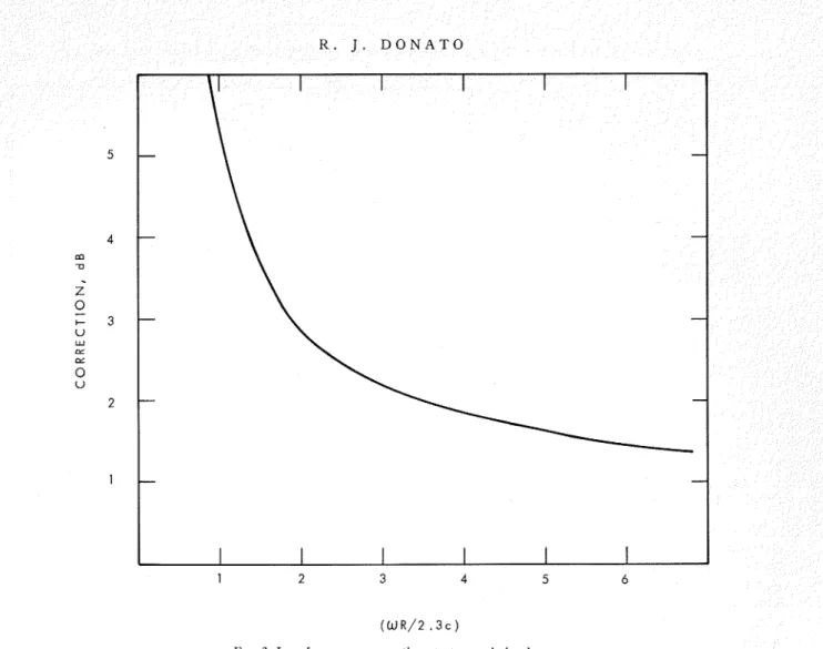
FIG. 3. Low-frequency corrections to transmission loss.
can be shown to be given by the actual wall area or-which is possibly a better procedure--find the radius of the largest circle we can
I ( k ) = ~ l ( k ~ ) [ ( k ~ ~ ) - ' + f ( R / k ) I - (2j22)-1Jo(kR) ( 2 6 ) fit into the area.
and We must now convolve I ( k ) with the 12 spectrum
I ( 0 ) = 3 R 2 / 8 . derived for the infinite area case. The value of F ( w ; k )
for the infinite area case is given by As a further simplification we shall find the effective
bandwidth of I ( k ) and use a rectangular wave I ( 0 ) F (w ; 12) = [ k , ( I ~ , ~ - k ~ ) ~ ] - ~ , (28) for the convolution process. Now where we have taken the incident sound field to be
three-dimensionally diffuse with the resulting
+
I
R (U ; 7 ) = (sink ,r)/kar.=+I
Jl(kR)/WKI;+2
I
Jo(kR)I
"o
= 1. ( 2 7 )
Then the effective bandwidth k o of I ( k ) is given by
l k ' I ( 0 ) k d k = 1
or
k J 2 = ( 1 6 / 3 ) + = 2 . 3 . (27')
T o find the effective R we may either equate a R 2 to
For the frequencies we shall be considering ko<ka, and so we can split the convolution into three parts
l
for k<ko,S,s
for k o < k < k a ,Sk"
for ka< k < k a + k o .k-ka
S O I J N D T R A N S M I S S I O N
F R E Q U E N C Y I N H E R T Z
(c)
F R E Q U E N C Y I N H E R T Z
( 4
FIG. 4. Theoretical and experimental transmission losses for studless double-leaf n.alls. (--) . experimental curve; (0) . theoretical ~ = 0 . 0 1 5 ; (m) : theoretical~=O.OlO; ( 0 and 0 ) : as above but with cosq correction a t higher frecluencies. (a) Each leaf 2.7 lb/ftZ, spacing
O N A T O
the curve is strongly peaked in the coincident region, one would expect the calculated loss to be too low. A computer study was made of this region and it was =k ~ i n - ' ( k / k , ) + ( k , ~ - k ~ ) t - k , , k_<ko; concluded that a fair allowance for the third-octave =k sin-'(k/k,) -k sin-'[(k -ko)/ka]+(ka2-k2)! containing the coincidence frequency was to add 4 dB -[ha2- (k-ko)2]J, ko_<k_<k,; to the coincidence loss figure. With this adjustment the =k sin-'(ka/ka) -k sinF'[(k -ko)/ka] agreement is good over most of the range. On the heavier wall (4.6 lb/ft2 on each side) two calculated -[ka2-(k-ko)2]h, ka_<k_<ko+ka; values are shown for the 1000-Hz point (Dh.1). The =0, k>ko+ka. (30) lower one, which is closer to the experimental point, is By carrying out the integrals outlined in Eq. 29 with using Eq. l3 at this frequency.
the values of G(k) calculated from Eq. 30, we may The worst fit is in the high-frequency region. I t derive values of the total normalized k spectrum ET appears that Eq. 18 is not a very good description for and the part of the k spectrum Eku which takes part in frequencies close to coincidence and that in this region sound radiation. If k a = ~ k o is written 8kaET/3R2=ko3 a modification of Eq. 19 would be more suitable. For X (~/6+P/2), then frequencies above coincidence, it seems that q=0.01 is the best value to use. At coincidence, on the other
8kmE& hand, q=0.015 gives better results. I t might be that
-
=ko3(7)
sin-l-+-+- P-1 ?rp38
3R2
0
6 2 in the high-frequency region where the transmissionloss changes rapidly with slope a correction should be applied for the third-octave bandwidth. This would -D2--@--1)2]f
-+-+-
.
(31) tend to bring the theoretical results down. I t could",)
also be that the original assumption of a cosp multiplier We also note that in the cavity no longer applies at the high frequencies. ET=($1
(k&)2[(r/6) (ko/ka)+3I- (32) Removing this multiplier brings these calculated figures closer to those observed. Substituting into Eq. 32 from Eq. 28, I t is heartening that the fit is as good as it is in the ET= ( ~ / 3 ) (ko/ka)+l. (33) midfrequency range. One would espect a good fit a t the lowest frequencies, but a t the middle frequencies For an infinitely large panel, ko -+ 0 and one might expect to run into trouble with the integration limits in Eq. 12. The good fit goes some way towardsET,=
1. (34) justifying the cavity model we have chosen. This result can, of course, be obtained directly fromVI. COMPARISON WITH PRACTICAL CASE
(k/ka)(ka2
-
k2)-idk = 1. The analytical representation, while introducingsome simplification, does represent the transmission As an illustration of the above procedure let us
consider the case of a 10x8-ft wall. The radius of the largest circle fitting into this area is 4 ft and from Eq. 27' k becomes 0.57 ft-'. From Eqs. 31 and 33 we may prepare the correction factors of Fig. 3 which are to be added to the results of the transmission loss calculation from Eq. 12.
V. COMPARISON WITH EXPERIMENTAL RESULTS
Figures 4(a)-4(d) show the comparison between the calculated and observed results for four studless gypsum board walls. Throughout, the damping factor has been chosen to be 0.010, which agrees with labora- tory measurements made on the vibration of strips and panels of the wall material.
An extra correction has been added a t the coincidence frequency itself. The calculated results apply for a particular frequency, whereas the esperimental points are those obtained using a third-octave filter. Thus, if
loss fairlyAaccurately. I t mus; be emphasized, though, that the problem solved is somewhat artificial-as are indeed most solutions to this problem. In a practical problem we would have to include the effect of the supporting studs. This effect may be twofold in that (1) the angular distribution of waves through the cavity may be distorted so that, in general, the effect would be to increase the transmission loss, and (2) the studs then~selves ]night be acting as a coupling medium between the two panels. The effect of any absorbing medium placed in the cavity would also have to be included in any con~prehensive theory. This should not be too much of a problem, however, as we could replace the real wavenumber for the waves in the cavity by a complex one. The resulting equations then become more coinplex but remain of the same general form.
An empirical attack on these problems using esperi- mental data is given in Appendiv A.
One very important parameter is the internal loss in the panel. In the present analysis we have taken
S O U N D T R A N S M I S S I O N T H R O U G H A D O U B L E - L E A F W A L L
q=0.010 to give a good fit, and this agrees with experi- with the 16-in. stud arrangement. Then the transmission mental evidence based on vibration studies, where q factor of the wall will be y1+Plalr0. For the studless was found to be 0.012. absorption-free case, the corresponding factor will be
TO. The ratio is thus P~(YI+YI/TO, and -10 Iogl0(P1a1
ACKNOWLEDGMENT + y 1 / ~ 0 ) is taken to be the difference of the STC values paper is a contribution from the Division of
lng Research, National Research Council of Canada, and is published with the approval of the Director of the Division.
APPENDIX A. EMPIRICAL APPROACH T O T H E EFFECTS O F STUDS AND
CAVITY ABSORPTION
e may carry out a very crude analysis of experi- a1 results to get some idea of the relative contribu- made by stud type, stud spacing, and an absorbing avlty. We shall take as our measures of the transmis- sion factor the sound transmission class (STC) of the wall. We have results on various walls for the STC of the walls with (a) no stud supports, (b) wooden studs 16 in. apart, (c) wooden studs 24 in. apart, and (d) metal channel studs 24 in. apart. These results are available both with and without 2 in. of mineral wool absorptive material in the cavities. We assume that the metal channels remove the effect of stud coupling. If the effect of the studs modifies the air transmission path by
a1 for the 16-in. spacing and a2 for the 24-in. spacing, if the effect of stud coupling for the wooden studs is 7 1
for the 16-in. spacing and y2 for the 24-in. spacing, and, finally, if PO, Dl,
P2
are the effects of the absorbing materials for the studless case and for the two differentfor the two cases. At first sight it might seem that we have seven equations with seven unknowns. This is not so, however, as there are four equations with three unknowns a2, r2/r0,
P2
and only two equations to determine Dl, al, T ~ / T O . A least-squares fit is first madeto the four equations. I t is found that
P2
is not too far from Po, and since P2>P1>Po, we takePl=Pz.
The results are shown in Table A-I. As we should expect,r1>r2 (the stud contribution is greater for 16-in. separation than for 24-in. separation). Similarly P2<P1.
The puzzling feature is that a1>a2, whereas simple reasoning would lead one to espect the reverse. T o make a1<a2 one would need 71/70 to be larger and 7 2 / 7 0
smaller, which is not very likely. Another possibility is that there is some coupling through the resilient channels. This would make a 2 smaller, which is a change in the wrong direction. Yet another possibility is that even for the studless case there may still be some contribution from the perimeter framework. The data show this to be small enough to be neglected. The most we can say is that both al and a2 are less than unity, but a t the moment the dependence upon stud spacing seems to be opposite to what one would expect. I t might also be that the STC measure is too blunt a tool to separate the various effects.
stud separations, we may write the following equations A. London, "Transnlission of Reverberant Sound through
for the STC to the studless no- Double Walls," L. L. Beranek and G. A. Work, "Sound Transmission through
J.
Acoust. Sot. Amer.22, 270-279 (1950). absorption case T O as Multiple Structures Containing I'lexible Blankets," J. Acoust.Soc. Amer. 21. 4 1 9 4 2 8 (1949). ~ I + Y I / T O = B , ffz+~2/70=C, a 2 = D, Do=A1, typically
P I ~ ~ + Y I / T O =
B1, P2az+y 2/70=c1, P2az=D1,.
0 dB -2 dB -4 dB -12 dB -3 dB -7 dB L - 13 dB. (35)As an example we take the case of absorption present
TABLE A-I. Air, stud, and absorbent transmission factors.
P. H. ~ h i ; e and A. Powell, "Transmission of Sound Vibration through a Rectangular Double Wall," J. Acoust. Soc. Amer. 40,
821-832 (1965).
R. H . Lyon and G. Maidanik, "Power Flow Between Linearly Coupled Oscillators, J. Acoust. Soc. Amer. 34, 623-639 (1962). R. H. Lyon and T . D . Scharton, "Vibrational Energy Trans- mission in a Three Element Structure," J. Acoust. Soc. Amer. 38, 253-261 (1965).
E. Eichler, "Thermal Circuit Approach to Vibrations in Coupled Systems and the Noise Reduction of a Rectangular Box," J. Acoust. Soc. Amer. 37, 995-1007 (1965).
P. H . White, "Sound Transmission of Double Flexible Walls Excited by Random Pressure 17ields," P h D thesis, Univ. Cali- fornia, Los Angeles (1965), 157 pp.
G. Maidanik, "Response of Ribbed Panels to a Reverberant Sound Field." T. Acoust. Soc. Amer. 34. 809-826 (1962).
A. J. price h n d M. J. Crocker, " ~ o u n d Transmission through Double Panels Using Slatistical Energy Analysis," J. Acoust. Soc. Amer. 47, 683-693 (1970).
lo L. L. Beranek, Ed., N o i s e R e d ~ ~ c t i o t z (McGram-Hill, New
York, 1960), p. 298.
'I E. Skudrzyk, Siiirple a n d Collrplex Vibrati~tg Sysle~irs
(McGraw-Hill, New York, 1968), p. 321.