Capacity Planning and Change Management in an Aerospace Overhaul Cell
byDavid Walker
B.S. Mechanical Engineering and Materials Science Duke University, 2007
Submitted to the MIT Sloan School of Management and the Department of Mechanical Engineering in Partial Fulfillment of the Requirements for the Degrees of
Master of Business Administration and
Master of Science in Mechanical Engineering
In conjunction with the Leaders for Global Operations Program at the Massachusetts Institute of Technology
June 2013
C 2013 David Walker. All rights reserved.
ARCHP&
jFMASSACHUSETTS INSilrrE OF TECHNOLOGY
MAY 3 0 2013
L IBRARIES
The author hereby grants to MIT permission to reproduce and to distribute publicly paper and electroniccopies of this thesis document in whole or in part in any medium now known or hereafter created.
Signature of Author
Department of Mechanica ngineering, MIT Sloan School of Manaement May 10 ,2013 Certified by
Certified by
Accepted by
Accepted by
(7
' Zey)nep Ton, Thesis Supervisor Adjunct Ass ' e Professor of Operations ManagementDavid Hardt, Thesis Supervisor Ralph E. and Eveln )Crosp ofessor ofMechanical Engineering
David Hardt Associate Department Heach Mechanic#l Engineering
Maura Herson, Director of MIT Sloan MBA Program MIT Sloan School of Management
This page intentionally left blank.
2 |1ag
Capacity Planning and Change Management in an Aerospace Overhaul Cell
byDavid Walker
Submitted to the MIT Sloan School of Management and the Department of Mechanical Engineering on May 10, 2013 in Partial Fulfillment of the Requirements for the Degrees of
Master of Business Administration and Master of Science in Mechanical Engineering
Abstract
Purpose - This thesis analyzes the transformation of the Small Components Cell in Pratt
& Whitney's aftermarket division through lean manufacturing techniques. The thesis focuses on
use of a labor capacity planning model, implementation of a new cell layout, and queuing theory. The project was 6.5 months long, running from June through December of 2012.
Findings - In Chapter 4, the capacity planning model shows that demand changes
significantly affect cell performance but that the product mix in the cell is even more crucial. The model highlights the best workforce allocations based on a given product mix or demand level. This analysis is expanded in a design of experiment that shows improving employee efficiency is the most effective means of expanding the capacity of the Small Components Cell. Four factors (employee efficiency, absenteeism, overtime, and the duration of employee breaks) have a significant effect on the ultimate capacity of the cell. The design of experiment allows the capacity planning model to be a useful predictive tool.
The transformation of the cell into a lean manufacturing flow line requires a significant investment in change management process, including a focus on the logistical details of transformation, continual reinforcement of the vision with the team, and cross-training the
workforce. The transformation resulted in a 94% reduction in non-value added part travel, a 72% reduction in flow reversals in the cell, and a 43% reduction in cell exits. Customer satisfaction metrics increase throughout the course of the project as well. Annualized EBIT performance improved by over 40% over the six months of the project, while the costs associated with reworking errors declined by more than 85%. However, on-time delivery of parts to customers failed to meet expectations because of the physical restructuring of the cell and a three month spike in demand which adversely effected cell capacity. Chapter 5 outlines the changes in business metrics, while Chapter 6 discusses recommendations and lessons learned.
Thesis Supervisor: David Hardt
Title: Ralph E. and Evelyn F. Cross Professor of Mechanical Engineering, Massachusetts Institute of Technology
Thesis Supervisor: Zeynep Ton
Title: Adjunct Associate Professor of Operations Management, MIT Sloan School of Management
This page intentionally left blank.
Acknowledgements
This thesis is an attempt to draw conclusions and lessons learned from six and a half months' work at Pratt & Whitney, one of the world's premier aerospace companies. To say that they taught me an incredible amount during that time is a ludicrous understatement.
First and foremost, thanks to General Manager Lori Gillette and Deputy General
Manager Craig Thompson for their tireless support and involvement in the project well before I set foot in Hartford. To Dave Beauchesne, Peter Steers, and Mike Franks for their willingness to guide this neophyte of a cell leader through the rigors of meeting customer expectations and managing the Small Components Cell. To Art Speranza, Ed Nelson, and their team, especially Andrew, Dave, and Kevin, for their assistance, patience, and good will in moving and re-installing dozens of pieces of manufacturing equipment in a four-month period.
To Simon Hecht, Bill Mucci, Kevin McMahon, and Chris Bennett for keeping the Small Components Cell on the right path in terms of quality, finances, and technical help. To Frank Hanrahan, Jay Chrzanowski, Henry Long, and David Fothergill for showing me the ropes as a cell leader. Particular thanks to Henry Long and Joe Wrubleski for their daily assistance with everything from union grievances to passing on the lessons learned from their operations
experience. To the lady and gentlemen of the Small Components Cell, you have taught me more than I can ever put into words. It was an honor to work with you.
To my thesis advisors, Professors Zeynep Ton and David Hardt for their welcome advice and recommendations. To the Massachusetts Institute of Technology and the staff of the Leaders for Global Operations program for the chance to be a part of such an amazing academic program. To my classmates and friends, who transformed the program from an amazing academic
experience into a truly wonderful two years. This thesis would be less than a pamphlet if it weren't for all of you. That being said, you might wish that it were a pamphlet by the time you finish reading it.
Finally and most importantly, thanks to my loving wife Renee for putting up with four moves in two years. Your constant encouragement and good-natured support buoyed me when I struggled and highlighted the good times. Both Renee and I wish to express our love to our families for their central role in our lives.
This page intentionally left blank.
Table of Contents
A b stract... 3 Acknowledgements... 5 List of Figures... 10 L ist of T ables ... 12 Glossary of Acronyms ... 13 Chapter 1 - Introduction... 14Chapter 1.1 - Problem Statement, Motivation, and Hypothesis ... 14
Chapter 1.2 - Research Methodology... 15
Chapter 1.3 - Thesis Outline... 15
Chapter 2 - Company and Project Context... 16
Chapter 2.1 - Brief History of Pratt & Whitney ... 16
Chapter 2.2 - Pratt & Whitney's Role in Aftermarket Operations ... 22
Chapter 2.3 - Competitors and Customers... 25
Chapter 2.4 - An Overview of the Small Components Cell ... 30
Chapter 2.4.1 - Part Families and an Introduction to Jet Engines... 31
Chapter 2.4.2 - Workforce ... 35
Chapter 2.4.3 - Working Environment ... 38
Chapter 2.4.4 - Processes and Equipment... 41
Chapter 3 - Pre-Project Status and Challenges... 44
Chapter 3.1 - Pre-Project Cell Metrics ... 44
Chapter 3.1.1 - Market Feedback Analysis... 44
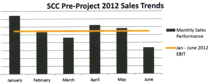
Chapter 3.1.2 - Sales, Costs, and EBIT Performance ... 45
Chapter 3.1.3 - On-Time Delivery... 49
Chapter 3.1.4 - Cost of Rework ... 51
Chapter 3.2 - Political, Cultural, and Strategic Considerations... 53
Chapter 3.2.1 - Strategic Lens... 53
Chapter 3.2.2 - Cultural Lens... 55
Chapter 3.2.3 - Political Lens ... 57
Chapter 3.2.4 - Summary of Cultural, Political, and Strategic Considerations ... 58
Chapter 4 - Transforming the Small Components Cell... 60
Chapter 4.1 - Why Use Lean Manufacturing Techniques? ... ... . . 61
Chapter 4.2 - Capacity Planning... 63
Chapter 4.2.1 - General Model Development and Assumptions ... 63
Chapter 4.2.2 - Pratt & Whitney-Specific Model Development... 66
Chapter 4.2.3 - Model Variants... 73
Chapter 4.2.4 - Efficiency Rates and Implications ... 75
Chapter 4.2.5 - Employee Capacity Planning for Demand Changes... 77
Chapter 4.2.6 - Equipment Capacity Planning for Demand Changes... 79
Chapter 4.2.7 - Capacity Planning for Variations in Product Mix... 81
Chapter 4.3 - Capacity Planning Design of Experiment ... 85
Chapter 4.3.1 - Procedure Summary... 86
Chapter 4.3.2 - Experimental Data and Results... 87
Chapter 4.3.3 - Conclusions of the Design of Experiment ... 95
Chapter 4.4 - Process Analysis and the Shared Services Area... 96
Chapter 4.5 - Planning Considerations and Constraints... 103
Chapter 4.6 - Master Schedule ... 104
Chapter 4.7 - Manufacturing Lines #1 and #2... 105
Chapter 4.7.1 - Small Components Cell Queuing: Capacity and Product Mix ... 106
Chapter 4.7.2 - Small Components Cell Queuing: Travel, Reversals, and Exits ... 112
Chapter 4.8 - Cross-Training Plan... 116
Chapter 4.8.1 - Example: Effectively Cross-Training Three Machinists ... 117
Chapter 5 - Data Analysis: Small Components Cell Performance... 121
Chapter 5.1 - Market Feedback Analysis ... 122
Chapter 5.2 - Sales, Costs, and EBIT Performance... 124
Chapter 5.3 - On-Time Delivery... 128
Chapter 5.4 - Cost of Rework... 129
Chapter 5.5 - K ey Findings... 131
Chapter 5.5.1 - Demand Variability and Product Mix... 132
Chapter 5.6 - Future Trends for the Small Components Cell... 134
Chapter 6 - Recommendations and Lessons Learned ... 135
Chapter 6.1 - Recommendations ... 135
Chapter 6.1.1 - Low-Hanging Fruit ... 135
Chapter 6.1.2 - Difficult but Attainable... 138
Chapter 6.1.3 - Challenging Opportunities... 141
Chapter 6.2 - Lessons Learned ... 143
Chapter 6.2.1 - Importance of Communication ... 143
Chapter 6.2.2 - Organizational Boundaries... 146
Chapter 6.2.3 - Attention to Details and Promise Integrity ... 147 Chapter 6.3 - Conclusion ... 149 Reference List ... 151
List of Figures
Figure 1: Pratt & W hitney company logo... 17
Figure 2: 2009 UTC business unit contributions to company revenue... 20
Figure 3: 2009 revenue of all UTC business units... 21
Figure 4: 2009 operating profits of all UTC business units... 21
Figure 5: 2009 operating margins of all UTC business units ... 22
Figure 6: Map of the Pratt & Whitney aftermarket facilities around the world. ... 23
Figure 7: Overhead picture of the Pratt & Whitney facility ... 25
Figure 8: Value added to an aircraft by component... 26
Figure 9: Estimated size of the 2010 aerospace overhaul market... 26
Figure 10: 2011 revenue for the 'Big Three' engine OEMs... 27
Figure 11: Market shares of the major engine manufacturers by volume ... 28
Figure 12: 2012 sales for the Small Components Cell by customer... 29
Figure 13: Market sizes and estimates from 2008 through 2020... 30
Figure 14: Sample pictures of the four different part families... 32
Figure 15: Small Components Cell work volume by part family... 33
Figure 16: Schematic of a GP7200 turbofan jet engine... 34
Figure 17: Employee experience within the Small Components Cell... 37
Figure 18: Employee experience within the Small Components Cell... 37
Figure 19: Scanned images of two Pratt & Whitney badges ... 38
Figure 20: First and second quarter 2012 MFA results for the SCC ... 45
Figure 21: First and second quarter 2012 EBIT performance ... 46
Figure 22: First and second quarter 2012 CTSC EBIT performance ... 47
Figure 23: First and second quarter 2012 sales... 47
Figure 24: First and second quarter 2012 overtime percentages ... 48
Figure 25: First and second quarter 2012 overtime percentages ... 49
Figure 26: 2012 On-time delivery for the Small Components Cell... 50
Figure 27: 2012 On-time delivery for Connecticut Stators and Components ... 51
Figure 28: 2012 Cost of rework for the Small Components Cell... 52
Figure 29: 2012 Cost of rework data for Connecticut Stators and Components ... 52
Figure 30: Organizational chart of Connecticut Stators and Components (CTSC)... 55
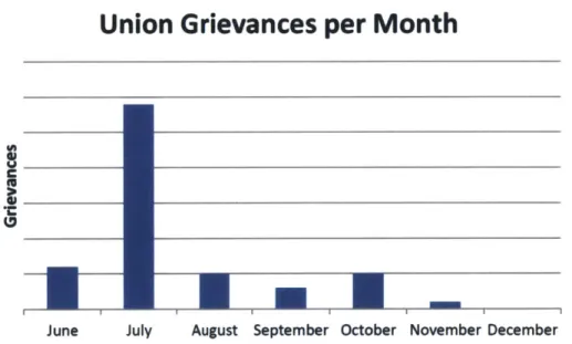
Figure 31: Summary of union grievance activity in the Small Components Cell ... 58
Figure 32: Illustration of capacity planning model... 67
Figure 33: Example demand input section of capacity planning model... 69
Figure 34: Capacity Inputs section of the model... 69
Figure 35: Example processes of the CLU part family... 70
Figure 36: Example summation table for the capacity planning model ... 72
Figure 37: Ratios of the work volume of the Small Components Cell by part family... 78
Figure 38: A graphical representation of Table ... 79
Figure 39: A graphical representation of Table 6. Equipment capacity vs. demand... 81
Figure 40: Ratios of the average product mix... 82
Figure 41: LPT-heavy product mix... 82
Figure 42: A graphical representation of Table 7. Required headcount vs. demand... 84
Figure 43: Normal plot of the results of the sparsity of effects experiment ... 88
Figure 44: Residual plots of the 24 sparsity of effects experiment ... 89
Figure 45: Normal plot of the 24 experiment with all higher order terms ... 90
Figure 46: Residual plots of the 24 experiment, including higher order terms ... 91
Figure 47: Residual plots of the 24 centerpoint experiment... 92
Figure 48: Normal plot of the results of the 34 experiment ... 93
Figure 49: Residual plots of the 34 full-factorial experiment ... 94
Figure 50: Parameter estimates of the 34 full-factorial experiment ... 95
Figure 51: Floor plan of the Small Components Cell prior to the start of the project... 97
Figure 52: Proposed layout for the shared services area... 100
Figure 53: New floor plan of the Small Components Cell. ... 102
Figure 54: Process flow for a machine move... 104
Figure 55: Overview of the project schedule... 105
Figure 56: Comparison of queue times and processing times ... 108
Figure 57: Trends in the mean queue time as demand increases... 109
Figure 58: Mean queue time trends with LPT-heavy mix and increasing demand ... 110
Figure 59: Trends in the mean queue time as demand increases... 111
Figure 60: Straight-line distances between sequential processes ... 114
Figure 61: Floor plan of the Small Components Cell at project completion... 115
Figure 62: Baseline training example situation ... 118
Figure 63: A representation of a fully cross-trained scenario... 119
Figure 64: A representation of a partially cross-trained plan ... 120
Figure 65: MFA scores prior to and during the project ... 122
Figure 66: Comparison of 2012 MFA scores ... 124
Figure 67: 2012 EBIT performance for the Small Components Cell... 125
Figure 68: Small Components Cell sales trends in 2012... 126
Figure 69: Monthly overtime percentages ... 127
Figure 70: Monthly overtime percentages ... 127
Figure 71: 2012 SCC on-time delivery information... 129
Figure 72: Cost of rework for the Small Components Cell ... 130
Figure 73: Average WIP levels during the project in the Small Components Cell... 133
Figure 74: Comparison of product mixes during the project... 133
Figure 75: Examples of visual aids for tracking on-time performance. ... 138
Figure 76: Union grievances by month... 145
Figure 77: A summary of major lessons learned throughout the project... 146
Figure 78: Process steps to move a piece of equipment. ... 147
Figure 79: Shop floor temperature vs. hours missed ... 148
List of Tables
Table 1: Performance comparison of the SCC to job design criteria. ... 40
Table 2: Sample results from one 100-day simulation of the manpower capacity... 73
Table 3: Sample results from one 100-day simulation of the equipment capacity... 74
Table 4: Baseline efficiency rates specific to each occupation code ... 76
Table 5: Required headcount vs. demand... 78
Table 6: Machine over-capacity percentage vs. changing demand ... 80
Table 7: Required headcount vs. demand for an LPT-heavy product mix ... 83
Table 8: Indications of fit for the 24 sparsity of effects experiment ... ,88
Table 9: Indications of fit for the 24 experiment with higher order terms included. 90 Table 10: Indications of fit for the 24 experiment with centerpoints included ... 92
Table 11: Indications of fit for the 34 full-factorial experiment... 93
Table 12: Comparison of the similarities between part families' repair processes ... 99
Table 13: Comparison of pre- and post-transformation queuing metrics... 113
Table 14: Comparison of training plans... 120
Table 15: Qualitative performance summary ... 121
Glossary of Acronyms
Meaning Description
ACE Achieving Competitive United Technologies Corporation's overarching lean
Excellence manufacturing system
CLU Vane Cluster One of four part families in the Small Components Cell
CNC omputer/Numerical Method for controlling machine tools with a high degree
Control of precision
CTSC Connecticut Stators and The larger business unit of which the Small Components
Components Cell is a part
Means of discovering the relative strengths of different DOE Design of Experiment variables with minimum resources
EBIT Earnings Before A common means of tracking financial performance; it
Interest and Taxes removes the variable effects of interest and tax rates Environmental Health An important organization within Pratt & Whitney that
EH&S and Safety ensures employee safety and minimizes environmental
impact
FAA Federal Aviation Regulatory body responsible for all aspects of civil Administration aviation, including repairs to jet engines
Fluorescent Penetrant An effective method for locating cracks in metallic FPI Inspection structures without destroying the structure itself HPC High Pressure A general term for engine stages prior to combustion,
Compressor also a part family in Small Components
HPT High Pressure Turbine A term for power-generating engine stages after combustion, also a part family in Small Components Independent Identically Random variables that are mutually independent and
Distributed have the same probability distribution
LPT Low Pressure Turbine A term for power-generating engine stages after combustion, also a part family in Small Components MFA Market Feedback The process of collecting extensive performance
Analysis feedback from customers; the surveys themselves
MMP Material Management System of managing inventory cooperatively between Program Pratt & Whitney and a customer
NDT Non-Destructive Quality checks that do not destroy the components
_______ Testing __ _ _ _ _ _ _ _ _ _ _ _ _ _ _ _ _ _ _ _ _ _ _ _ _
OEM Original Equipment The company responsible for the initial fabrication of the Manufacturer components or systems
Percentage of time Small Components returns parts
on-OTD On-Time Delivery time to customers
SCC Small Components Cell Organization at the center of this thesis
UTC United Technologies Parent company of Pratt & Whitney Corporation
WIP Work-In-Process Inventory currently moving through the processes or
W I W buffers in a defined area
Chapter 1 - Introduction
Chapter 1.1 - Problem Statement, Motivation, and Hypothesis
As the high-pitched whine of a jet engine fades, a team of trained technicians approaches
the plane for scheduled maintenance. After completely removing the engines from the wings and
disassembling them, the parts are sent to designated repair centers for the overhaul work that will
permit the engine to operate safely and efficiently for thousands of flight hours.
Within one of those designated repair centers at Pratt & Whitney's East Hartford
location, Operations Manager Craig Thompson and General Manager Lori Gillette are
concerned. One of the four aftermarket overhaul cells within Gillette's Connecticut Stators and
Components (CTSC) business unit is not meeting its business goals. With over $12 million in
annual revenue, the Small Components Cell represents a sizable investment for the company.
However, on-time delivery performance is not meeting Pratt & Whitney's aggressive targets and
the Small Components Cell is not as profitable as it has been in the past. Customer feedback also
indicates increasing displeasure with the turnaround time and the perceived value of the services
provided. As Thompson and Gillette review the business metrics for the cell, they consider
restructuring the cell from a job shop to a flow line to improve the situation, as well as the need
to accurately determine the capacity of the mixed-model cell.
The project that emerges from their brainstorming session tests the hypothesis that a lean
manufacturing flow line is more efficient than a traditional job shop structure. As a part of this
goal, a capacity model of the cell has been created, and a cross-training plan improves the cell's
flexibility. This project is equally focused on leadership development through the direct
supervision of 20 unionized hourly employees. Motivating the team in the face of significant
changes throughout the cell can be a challenge, particularly with the incredible depth of
experience that many employees possess. This is frequently the most rewarding component of
the project, especially when the team unites to carry out dynamic improvements in
month-over-month delivery performance.
Chapter 1.2 - Research Methodology
Research was primarily conducted through direct interactions with the shop floor and
through an analysis of capacity planning challenges faced under similar situations. As a part of
the project, a plan for the 70+ pieces of equipment, cabinets, and tools has been developed in
accordance with lean manufacturing principles. Capacity planning and variance analyses based
on both historical data and studies on current work orders are complete. The new cell layout
provides the headcount and equipment needed to efficiently meet customer demand. Additional
capital requests have been submitted to eliminate process flow reversals and cell exits wherever
possible. An aggressive cross-training plan is in place to ensure that the employees are
comfortable with a wide variety of operations throughout the cell. External research focuses on
capacity planning models, queuing theory, and variation within aerospace aftermarket
organizations.
Chapter 1.3 - Thesis Outline
Chapter 2 discusses background information on the company, competitors, and
customers. Chapter 3 covers the pre-project metrics for the SCC and a brief analysis of the cell
through cultural, political, and strategic lenses. Chapter 4 dives into the cell transformation itself,
the capacity planning model that was used to develop the floor plans, the implementation of the
cell restructuring, and the cross-training plan for the employees. Chapter 5 walks through the
data analysis and summarizes key findings. Chapter 6 discusses the conclusions and personal
lessons learned.
Chapter
2 - Company and Project Context
This chapter focuses on providing a high-level overview of Pratt & Whitney's company
history, the company's role in the aftermarket operations business, and a broader look at Pratt &
Whitney's customers and competitors within this marketplace. Chapter 2.4 delves into project
context, giving specific insights into the types of parts the Small Component Cell repairs, an
overview of the employee skill-sets within the SCC, and the general types of equipment and
processes used to overhaul engine components. This allows the reader to more fully understand
the situation from both a large-scale industry perspective and to gain additional awareness of the
project's specific context.
Chapter 2.1 - Brief History of Pratt & Whitney
In the early days of powered flight, inventor and airplane enthusiast Frederick Rentschler
and engineer George Mead approached their employers at Wright Aeronautical with a plan for a
new radial aircraft engine. Citing the declining demand for such products following the end of
World War I, Rentschler's aggressive capital plan was denied. Rather than being dissuaded,
Rentschler and Mead recognized the opportunity in Wright Aeronautical's decision and began a
search for other manufacturers interested in new products. In 1925, the Pratt & Whitney Machine
Tool Company of East Hartford, Connecticut extended a loan to Rentschler to develop the
air-cooled radial engine dubbed the R-1340 Wasp (Pratt & Whitney, 2008). Utilizing loaned capital
and factory space efficiently, Rentschler and Mead completed the design, manufacturing, and
testing phases in a mere eight months. The engine easily met the Navy's power and weight
requirements, and Pratt & Whitney Aircraft was born. In the developing field, Pratt & Whitney's
products quickly gained a reputation for reliable performance, a proud legacy that continues
today in the "Dependable Engines" slogan on the company logo.
Figure 1: Pratt & Whitney company logo. Image courtesy of Pratt & Whitney. All rights reserved by Pratt & Whitney and United Technologies Company
The rapidly growing company was soon joined with several others in a spate of mergers
and acquisitions driven by the Great Depression. Modem-day companies that were once joined
under the umbrella of the United Aircraft and Transport Company include The Boeing Company,
United Airlines, Sikorsky Aircraft Corporation, Triumph Aerostructures (Vought),
Hamilton-Sundstrand, and Spirit AeroSystems. Following the Air Mail Act of 1934, the combined
company was split to preserve the most profitable companies, with Boeing and United Airlines
separating from Pratt & Whitney's new parent company, United Aircraft. World War II saw
rapid growth in demand for Pratt & Whitney's products, leading to significant advancements in
engine technology and increasing factory footprints, primarily near the company's headquarters
in East Hartford. From pre-war employment levels of 5,200 employees, Pratt & Whitney saw
such large spikes in demand that the company boasted nearly 40,000 staff members by 1943
(Company Histories: Pratt & Whitney, 2012).
In spite of the wartime successes, significant challenges lay ahead. Following postwar
cuts, employment dropped to 6,000 as demand ground to a halt. More than 85% of Pratt &
Whitney's orders were cancelled at the end of 1945 (Pratt & Whitney History, 2012). Risking his
business on the perceived future of jet engines, Rentschler ordered the internal development of a
jet engine that could outperform the competition. Pratt & Whitney's eventual solution, the J57,
was unveiled in 1952 and produced 13,500 pounds of thrust, far outstripping the competition's
engines, which had planned thrust ratings between 4,000 - 7,000 pounds (Ibid). Over 21,000 of
these engines were produced, and Pratt & Whitney was once again on solid financial footing
(Company Histories: Pratt & Whitney, 2012).
The momentum built during the commercial dawn of the jet age. Pratt & Whitney's
products in the newly developed Douglas DC-8 and Boeing 707 answered the call of Pan Am
president Juan Trippe for domestically-produced commercial airliners (Ibid). The fact that Pratt
& Whitney secured placements on both types of aircraft allowed the company to capture the
majority of the jet engine market through the mid- 1 970s (Pratt & Whitney History, 2012). In
conjunction with the success of the J57, which powered the iconic Boeing B-52 Stratofortress,
and the J59D, operating on the legendary Boeing 747, Pratt & Whitney began to dominate both
the military and commercial facets of engine production. This was particularly beneficial for the
company, as it was a time that aircraft and engine technologies were firmly enshrined in the
psyche of the country. The company continued to thrive during the Cold War, winning contract
after contract on some of the most technologically advanced and well-recognized projects of the
time, including the U-2 Dragon Lady and the fastest air-breathing manned aircraft, the SR-71
Blackbird.
Pratt & Whitney's enviable achievements came with a cultural price; a willingness to
take on risky projects with customers grown accustomed to success. Serious technical problems
plagued the TF30 engines powering the F- 111 Aardvark and F-14 Tomcat. These problems were
compounded by inter-service disagreements between the U.S. Navy and U.S. Air Force, resulting
in work-scope expansions. The final aircraft designs did not meet their original intent, and
airframe manufacturers General Dynamics and Grumman cited Pratt & Whitney's engines as the
ultimate source of the schedule delays and underperformance (Pratt & Whitney History, 2012).
The subsequent F100 engine, which powers the F-15 Eagle and F-16 Fighting Falcon, was a
near-disaster for the company in the early stages of development. A test-stand explosion forced
Pratt & Whitney into an incredibly costly, self-funded redesign cycle. By the time the company
was able to re-introduce the engine, competitor General Electric had successfully petitioned the
U.S. Air Force to allow its F 110 engine as a second power plant, capturing over 75% of the
F 100's market (Company Histories: Pratt & Whitney, 2012).
Pratt & Whitney's woes during the 1970s extended to the commercial realm as well.
Although the company's products were well-represented on larger commercial aircraft, Pratt &
Whitney was phased out of the best-selling Boeing 737 in the 1980s in favor of the General
Electric and SNECMA CFM56. Compounding the blow was another loss to the CFM56 on the
high-rate Airbus A320 line, though Pratt & Whitney was able to regain portions of the business
in the late 1980s by forming a consortium with Rolls-Royce, Japanese Aero Engine Corporation,
and MTU Aero Engines (Pratt & Whitney History, 2012).With nearly 13,000 Airbus A320 and
Boeing 737 variants in service today and over 6,500 firm orders for the two programs, these
on-going product families represent a devastating loss of market share to rivals General Electric and
SNECMA.
Today, Pratt & Whitney has nearly 16,000 commercial engines in flight, accruing more
than 1 billion flight-hours since their installation (Products, 2008) (Commercial Engines, 2008).
In addition to extensive work with domestic defense programs, including the EA-6B Prowler,
F-111 Aardvark, F-14 Tomcat, F-15 Eagle, F-16 Fighting Falcon, F-22 Raptor, F-35 Lightning II,
B-52 Stratofortress, KC- 135 Stratotanker, AWACS, and C- 17 Globemaster, Pratt & Whitney
provides military engines to 27 international armed services (Military Engines, 2008). Almost
11,000 Pratt & Whitney military jet engines are currently in service (Ibid). As a part of United
Technologies Corporation, Pratt & Whitney provided over $9.0 billion (23.8%) of UTC's $38.1
billion in revenue in 2009 and reported an operating profit of $1.3 billion, resulting in an
operating margin of 14.6% (Clearwater Corporate Finance, LLP, 2011). Figures 2 through 5
show key information about Pratt & Whitney in relation to other business units within UTC
(Ibid).
2009 Business Unit Percentages of Total UTC Revenue
-0.6%
" Otis
* Carrier
" UTC Fire & Security
* Pratt & Whitney * Hamilton Sundstrand U Sikorsky
* Other
Figure 2: 2009 UTC business unit contributions to company revenue
2009 UTC Business Unit Revenues ($Billions) -0.214
* Otis
" Carrier
" UTC Fire & Security
* Pratt & Whitney
" Hamilton Sundstrand * Sikorsky
* Other
Figure 3: 2009 revenue of all UTC business units
2009 UTC Business Unit Operating Profits ($Billions)
* Otis
* Carrier
* UTC Fire & Security
" Pratt & Whitney
" Hamilton Sundstrand
" Sikorsky * Other
Figure 4: 2009 operating profits of all UTC business units
2009 UTC Business Unit Operating Margins 0.0%
* Otis
" Carrier
* UTC Fire & Security
* Pratt & Whitney
" Hamilton Sundstrand
" Sikorsky
" Other
Figure 5: 2009 operating margins of all UTC business units
Chapter 2.2 - Pratt & Whitney's Role in Aftermarket Operations
Throughout this storied and tumultuous background, Pratt & Whitney has been a
significant force in the manufacture of a wide variety of engines and their components.
Recognizing that the market for aircraft engines extends far beyond original equipment
manufacturing, Pratt & Whitney maintains a strong presence in aftermarket operations as well.
The large numbers of Pratt & Whitney commercial and military engines currently in operation
provide an expansive market landscape. Additional information on the overhaul market for
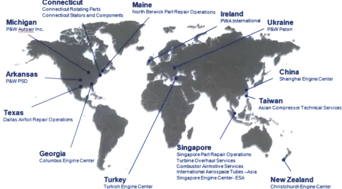
engines can be found in Chapter 2.3. The company repairs over 1 million engine components per
year through a global array of engine service centers (Part and Accessory Repair, 2008).
Previously seen as a secondary market to original equipment manufacturing, Pratt & Whitney's
role in aftermarket operations is developing in several important ways.
Connecticut Maine
Connectict Rotating Parts North Berwick Part Repair Operations Co nn ectiwct Stato rs an d Co mpo nertIeln
Michigan Iternatio"a' "W Ukraine
P&WAutoair Inc. P&W Paton
Arkansas Cia
P&W PSD Shanghai Engine Center
Taiwan
Asian Compressor Technical Services
Texas
Dallas Airfoil Repair Operations
mgapore
Georgia SingaporePartRepairOperations V Columbus Engine Center Turbine Overhaul Services
CombustorAirmotive Services International Aerospace Tubes -Asia
Turkey Singapore Engine Center- ESA New Zealand Turkish Engine Center Christchurch Engine Center
Figure 6: Map of the Pratt & Whitney aftermarket facilities around the world.
One such development is the advent of holistic material management programs (MMPs).
Owing to the high capital cost of a new engine and the high operating costs associated with jet
engines, many airlines find it economically attractive to allow an outside party to bear the
corresponding inventory costs. As a result, Pratt & Whitney has several divisions that interface
directly with customers like United Airlines and Delta Air Lines. These MMP organizations
facilitate overhauls for the end user, allowing the airlines to reduce their inventory holding costs
and permitting Pratt & Whitney to maintain market control over its products. This control is
particularly crucial in light of the tendency of engine manufacturers to expand their aftermarket
divisions through repairs on competitors' engines. Pratt & Whitney captures market share by
doing just that, as the company holds FAA approval to conduct overhauls on General Electric
and SNECMA CFM56 engines (Engine Overhaul, 2008). This strategic win is crucial to
recapturing a portion of the revenue in the Boeing 737 and Airbus A320 engine market.
Beyond simply maintaining a customer's engines, aftermarket operations have been
expanding into the digital age. Pratt & Whitney offers rigorous data analysis of 'on-wing'
engines around the world. By comparing critical engine operating parameters to known
performance standards, the company can anticipate future maintenance needs and assist
customers with pre-emptive overhauls and other services (Engine Health Monitoring, 2008).
Known as engine health monitoring, this business strategy benefits the customer through
improved on-wing engine efficiencies and more predictable, cost-effective maintenance cycles.
Pratt & Whitney benefits through additional 'womb to tomb' control of its products and the
ability to more accurately predict its cash flows in a historically cyclic industry. Furthermore,
this data collection allows Pratt & Whitney to directly compare in-flight engine data to
competitors' products, permitting engineering groups to prioritize improvements for future
products and additional repair strategies for existing engines.
These strategies of expanding aftermarket operations are critical to what industry insiders
see as the next step of engine manufacturing and service: 'fixed price per engine flight hour'
contracts (Anonymous, Personal Interview with Pratt & Whitney Executive, 2012). In this
model, the end user leases the engines from the manufacturer for a per-unit-time rate that
includes all associated maintenance. This situation benefits both the airlines and Pratt & Whitney
by helping to stabilize revenue during the course of a fiscal year. Under current operating
conditions, the airlines and Pratt & Whitney see major expenditures and revenue, respectively,
only when the engine returns for maintenance. As this situation develops unpredictably, neither
company has effective control of large amounts of cash. In an industry with very high capital
requirements, these expenses can devastate plans for fleet upgrades, new engine development
programs, and other investments.
Over the past decades, Pratt & Whitney's aftermarket operations have developed several
reinforcing strategies, from material management programs (MMPs) and engine health
monitoring programs to fixed price per engine flight hour contracts. Each step enables Pratt &
Whitney to more effectively moderate their cash flows over the duration of the engine's life
cycle. Simultaneously, airlines are more thoroughly supported in their efforts to receive
high-quality maintenance from the OEM while carrying less of the inventory cost burden.
Figure 7: Overhead picture of the Pratt & Whitney facility in East Hartford, Connecticut. The circled building contains the Global Service Partners (aftermarket) division, including the Connecticut Stators and Components business unit and the Small Components Cell.
Chapter 2.3 - Competitors and Customers
After describing Pratt & Whitney's history and role within the aftermarket operations
space, this chapter concentrates on understanding the current commercial customers and
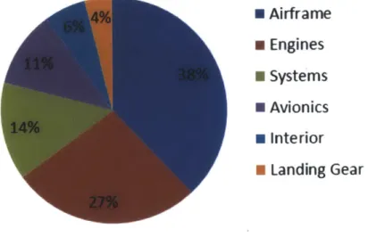
competitors within that market. Figure 8 outlines the fractional value of new components and
systems of an average new aircraft and Figure 9 provides an estimate of the size and breakdown
of the 2010 overhaul market (Clearwater Corporate Finance, LLP, 2011).
Component Value as a Percentage of Aircraft Value
* Airframe m Engines * Systems * Avionics * Interior * Landing GearFigure 8: Value added to an aircraft by component (Clearwater Corporate Finance, LLP,
2010 Estimated Global Overhaul Market
* Heavy Maintenance * Line-Side Maintenance N Components m Engines Total $428 Market Size:
Figure 9: Estimated size of the 2010 aerospace overhaul market with percentages
associated with the different types of overhauls performed (Clearwater Corporate Finance, LLP,
2011). Note that 'Line-Side Maintenance' refers to maintenance on the flight line, while 'Heavy
Maintenance' refers to repairs performed in a specialized facility that is not on the flight line.
As befits a company with such a rich history, Pratt & Whitney maintains a diversified,
global commercial engine customer base that includes the OEMs of the aircraft themselves as
26 | P a g e
well as most major airlines. The company currently boasts 7 different types of commercial jet
engines: the V2500, GP7200, PW2000, PW4000 engine family, PW6000, JT8D, JT9D, and the
PurePower @ PW1000G Geared TurbofanTM engine (Commercial Engines, 2008). In addition,
Pratt & Whitney Canada, a sister division, produces a variety of turbofan, turboprop, and
turboshaft engines for business- and commuter-style aircraft (Ibid). Pratt & Whitney's jet
engines are found on an astounding array of aircraft, from the smaller regional jets including
Mitsubishi's newest regional jet offering, Bombardier regional jets, the Russian Irkut MC-2 1,
and Embraer regional jets to the largest aircraft in the skies: the double-decker Airbus A380 and
Boeing 747 (Ibid).
Of course, Pratt & Whitney is not alone in this market space. The company faces serious
challengers, including General Electric's Aviation division and Rolls-Royce. When discussing
the engine market, this relatively stable triumvirate of engine OEMs is often described as the
'Big Three.' Market position between the Big Three has been fluid, and Pratt & Whitney is
currently the smallest of the three in terms of revenue, as shown in Figure 10 (Rolls-Royce,
2011) (General Electric, 2011) (United Technologies Corporation, 2011).
2011 Revenue
$20.0 C$15.0
-$10.0
-$5.0
-Pratt & Whitney Rolls Royce, pic GE Aviation
Figure 10: 2011 revenue for the 'Big Three' engine OEMs
In order to mitigate risk and defray the large capital expenditures associated with new
engine development and testing, several risk-sharing joint ventures exist. These unions of
convenience hold substantial portions of the market share, placing Pratt & Whitney in the
interesting position of frequently designing and marketing engines in conjunction with their
biggest competitors. Although this model has been stable in recent history, a recent development
could begin to re-order the market. The introduction of the Pratt & Whitney PurePower @
PW1000G Geared Turbofanl" engine promises major fuel efficiency improvements and is
initially targeted at regional jets and the single-aisle commercial airliner market segment. The
engine is the only option or is the primary power plant on the new Mitsubishi and Bombardier
regional jets, as well as the Airbus A320neo (new engine option). This represents a particularly
vital step towards re-capturing portions of the high-rate regional jet and single-aisle markets that
were lost to CFM International and GE Aviation on the earlier versions of the Airbus A320 and
Boeing 737 aircraft families.
Engine Manufacturers' 2011 Market Shares by Volume
* CFM International * GE Aviation
* Engine Alliance * Pratt & Whitney
" International Aero Engines
* Rolls-Royce * Others
1%
Figure 11: Market shares of the major engine manufacturers by volume (Clearwater Corporate Finance, LLP, 2011). Please note that the Engine Alliance is a joint venture between Pratt & Whitney and General Electric's Aviation division, while International Aero Engines is a joint venture between Pratt & Whitney, Rolls-Royce, Japanese Aero Engine Corporation, and
MTU Aero Engines. CFM International is a joint venture between General Electric's Aviation
division and French engine manufacturer SNECMA.
Transitioning from new engine manufacturing to overhaul, Pratt & Whitney's aftermarket
operations division interfaces directly with the same airframe OEMs, but also serves airlines and
their MMP groups directly. Major customers include domestic airlines such as Delta Air Lines,
United Airlines, and American Airlines. International relationships make up a large component
of the customer landscape as well, including Japan Airlines, Air China, Korean Air, and Emirates
among others. As previously mentioned, the airlines' MMP groups represent an important
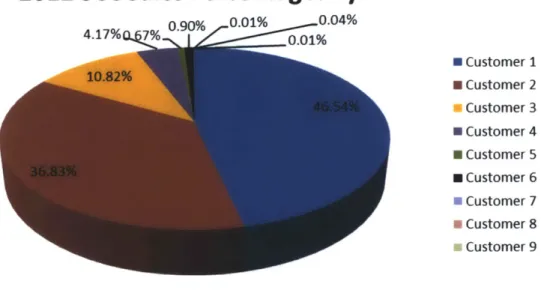
portion of Pratt & Whitney's aftermarket business. When specifically considering the Small
Components Cell, the market breakdown is diversified between domestic and international
airlines, as shown in Figure 12. A significant portion of the Small Component Cell's business
stems from MMP organizations. Because of the proprietary nature of this information, customer
names are not shared in conjunction with the volume of their business.
2012 SCC Sales Percentages by Customer
0.90% 0.01% 0.04% 4.17% 7% FO0.01% E Customer 1 * Customer 2 a Customer 3 * Customer 4 * Customer 5 N Customer 6 * Customer 7 a Customer 8 Customer 9
Figure 12: 2012 sales for the Small Components Cell by customer. This is a
representation of the Small Components Cell only and is similar, but not identical to, other business units within Pratt & Whitney's aftermarket division.
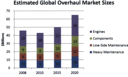
Looking forward, a 2011 Clearwater report notes global aftermarket revenue of $45.7
billion in 2009 alone, with solid growth expected throughout a 7-year horizon (Clearwater
Corporate Finance, LLP, 2011). As Pratt & Whitney plays a major role in all aspects of the
engine overhaul markets, this growth estimate bodes well for the company, particularly if the
new PurePower @ PW 1 000G Geared Turbofans engine meets performance expectations in the
new engine market. In summary, Pratt & Whitney operates in a cyclical industry which is
characterized by three dominant market players and a variety of joint ventures with other
companies. Competition is fierce and product lifecycles are best measured in decades.
Estimated Global Overhaul Market Sizes
70 60-50 S40 -m Engines N Components 4 30 - N Line-Side Maintenance 20 - U Heavy Maintenance 10 -0 2008 2010 2015 2020Figure 13: Market sizes and estimates from 2008 through 2020, predicting significant growth in the aerospace overhaul market (Clearwater Corporate Finance, LLP, 2011).
Chapter 2.4 - An Overview of the Small Components Cell
Previous chapters discuss Pratt & Whitney's history, its role within the engine overhaul
space and the commercial engine marketplace. This chapter focuses solely on the parts repaired
by the Small Components Cell, the workforce, the general types of processes used, and the
equipment in the cell. One of four overhaul cells within the Connecticut Stators and Components
(CTSC) business unit, the Small Components Cell consists of 20 hourly employees, 1 cell
engineer, and 1 cell leader. There are also more than 70 pieces of equipment, including weld
booths, CNC milling machines, super-abrasive machines, downdraft blend benches, and
inspection stations. From June 64, 2012 through December 2 0th 2012, I was the cell leader for
the Small Components Cell. Daily job responsibilities included prioritization of work, meeting
the expected operating metrics, supervising the hourly employees, and managing the
transformation project described in Chapter 4.
Chapter 2.4.1 - Part Families and an Introduction to Jet Engines
The Small Components Cell is a mixed-model cell which focuses on the overhaul of four
different part families, each of which contains many unique part numbers. In all, there are nearly
three hundred unique part numbers that are repaired within the cell. These components come
from the low pressure turbine, high pressure compressor, and high pressure turbine sections of
the PW2000, PW4000, and other Pratt & Whitney jet engine products. No military work is
performed in the cell. Made from a variety of temperature resistant metallic alloys, most parts are
smaller than 6" x 6" x 6" and weigh less than 3 lbs. The parts, however, differ radically in
geometry and processing steps between families. Low pressure turbine (LPT) components are
primarily thin metallic structures with a bonded 'honeycomb' surface. These parts serve to seal
off different stages of the low pressure turbine from one another. High pressure turbine (HPT)
duct supports are supporting structures for the various flow lines that snake throughout the
engine. High pressure compressor (HPC) shrouds provide airflow and pressure separation
between stages of the high pressure turbine stages. Vane clusters (CLU) are the small airfoils that
re-direct flow within the engine. Within the Small Components Cell, part families are usually
referred to by their three-letter designations: HPCs, LPTs, HPTs, and CLUs. Images of the
different part families are below.
Figure 14: Sample pictures of the four different part families. From left are the high pressure turbine (HPT) duct supports and the vane clusters (CLU). The right-most picture shows both the high pressure compressor (HPC) shroud in front of two different types of low pressure turbine (LPT) parts. For proprietary reasons, these images are not to scale and do not represent the full spectrum of geometries within each part family. All rights to these pictures are reserved
by Pratt & Whitney and United Technologies Corporation.
Generally, HPCs and CLUs make up the majority of the parts that arrive for repair, with
LPTs and HPTs forming the remaining portions of the inventory, as shown in Figure 15. The
degree of work performed on each part is driven by four primary factors: the thermal and
mechanical wear on the part, the location of the wear, the age of the part in flying hours, and the
material. Since many features have tolerances on the order of +/- 0.001 in., extreme care is taken
to ensure that the overhaul process itself does not damage the parts or exceed the allowable
dimensions.
Average Product Mix for SCC 2010-2012
* CLUs
* HPTs
* HPCs
LPTs
Figure 15: Small Components Cell work volume by part family. For proprietary reasons, these data have been disguised, though the trend is are representative of reality.
Furthermore, because of the long service life of the components and the high degree of
precision required, the unit cost of each part is significant. Mistakes have a very large impact on
the overall profitability of the business, especially since unserviceable parts require a new and
very expensive component to be purchased for the customer. As Ravindran, et al, notes in an
analysis of an overhaul center at Tinker Air Force Base, "Parts are overhauled and returned to
service for a fraction of the cost of a new part. A major overhaul may cost less than five percent
of the cost of a new engine in terms of labor, material, and replaced parts" (Ravindran, Foote,
Badiru, Leemis, & Williams, 1989).
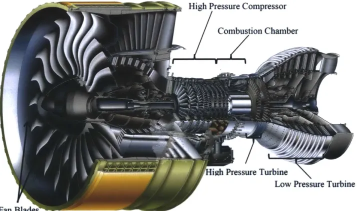
Having reviewed the four main part families in the Small Components Cell, the following
paragraphs discuss their place within a jet engine. In a high-bypass turbofan engine, the primary
components are a central compressor, the combustion chamber, and a power-generating turbine.
Upstream of these core components are the iconic fan blades at the inlet of the engine. As air
flows through the fan blades, a portion of the flow called bypass air is directed around the core.
The remaining portion of the flow is directed through the core, where all four part families from
the Small Components Cell are found.
As air enters the core, it meets a succession of rotating and stationary airfoils in the
compressor section of the engine. Each pair of rotating and stationary airfoils is known as an
engine 'stage.' Engine components are usually categorized by the stage to which the parts
belong. The rotating components force air into the intermediate chambers, increasing the
pressure. At the end of the compressor section, atomized fuel is sprayed into the combustion
chamber and ignited. The resulting explosion is channeled by the turbine blades through the
aft-facing nozzle. This airflow spins the turbine and the front fan blades, providing thrust and
electrical power to the aircraft through a mechanically coupled generator.
igh Pressure Turbine
Low Pressure Turbine
Figure 16: Schematic of a GP7200 turbofan jet engine. Image courtesy of Pratt & Whitney (Pratt & Whitney, 2008).
Chapter 2.4.2 - Workforce
The employees have a tremendous amount of skill in their respective functions and a
deep understanding of the processes and parts. On average, each of the twenty hourly associates
of the Small Components Cell have twenty-seven years of experience, and several employees are
nearing or have recently passed the forty-year service mark. Because of the slim margins for
error and the critical nature of the engine as a whole, it is crucial to discuss the employees who
complete the work as well as the type of work performed within the Small Components Cell.
Figures 17 and 18 show several different perspectives of the employees' experience levels. It is
important to note that employees are separated by 'occupation codes,' which specifically define
the types of roles that they conduct in the cell in accordance with the contract between Pratt &
Whitney and IAM District 26, which represents the employees in East Hartford. Employees can
only perform work within their occupation code.
The Small Components Cell has employees in five different occupation codes: the
machinists (occupation code 176H), surface mechanics (occupation code 344H), welders
(occupation code 380H), inspectors (occupation code 400H), and non-destructive inspection
technicians (occupation code 464H). One support group, the material handlers/expeditors
(occupation code 901H) is important to keep in mind as well. A brief description of the duties of
each occupation code is below.
" Machinists (1 76H): Machinists focus on operating CNC mills, drill presses, and
hand blending processes. In the Small Components Cell, they are also responsible
for the upkeep of tooling fixtures and for any required part assembly work.
" Surface Mechanics (344H): Surface mechanics perform surface preparations such as grit blasting, thermal spray, part cleaning, and etching.
* Welders (380H): Welders use tungsten inert gas welders or plasma welders.
Within the Small Components Cell, this skill is frequently used to add material to
ablated or damaged surfaces rather than to join parts.
* Inspectors (400H): Inspectors are responsible for visually and mechanically
confirming that contours, thicknesses, angles, radii, surface finishes, and other
critical features are within the acceptable design tolerances.
" Non-Destructive Inspection Technicians (464H): Non-destructive inspection
technicians analyze parts for surface and internal cracking, distortions, and voids.
Industry-standard methods include fluorescent penetrant inspection (FPI),
ultrasound, and X-ray.
" Material Handlers&xpeditors (901H): Expeditors are responsible for moving
parts across main aisles throughout the facility or between buildings. Since the
Small Components Cell was initially separated by an aisle and relies on certain
processes outside of the cell, this job code has an important impact on the
operation of the cell. There are no expeditors who directly report to the Small
Components Cell.
In certain occupation codes, there are 'lead' employees who hold additional
responsibilities, including helping to assign work, training other employees, troubleshooting new
repair methods, and tackling particularly difficult overhauls. In the Small Components Cell, both
leads are machinists with the 176H occupation code.
6-~asE
rec -15 Years' re 1 e
|
0- 5Years' Experien-ce | 6 1 Yer1 f rec 16 - 30 Yeas Enc 31der renc
14 years
37 years
31 years
Welders 380H
Figure 17: Employee experience within the Small Components Cell, organized by seniority order, with less senior employees on the left and the most senior employees on the right. Color codes represent the different occupation codes, and the key is shown at the bottom of the figure.
1767
Smac-ll Comiponents Cell (SCC) - by Job Code an3id Seniority
176H 400H 380H __344H 46H
37 years 24 Ors
31 years
14 years
Figure 18: Employee experience within the Small Components Cell, organized by occupation code, with less senior employees lower in their respective occupation code and the most senior employees at the top. Color codes represent the different occupation codes and follow the labeling convention in Figure 17.
The vast majority of the blue Pratt & Whitney badges within the Small Components Cell
show the 'eagle wing' emblem, signifying at least 25 years of employment with the company, as
seen in Figure 19. Many also sport the coveted gear pattern, signifying that they have at least one
patent to their name.
I
Figure 19: Scanned images of two Pratt & Whitney badges, which are powerful symbols of the company culture. Note the "eagle wings" and gear icon in the badge on the left, which denote service time and a patent, respectively. Longevity and technical contributions are highly prized in the organization.
Overall, the team has more than 490 collective years of experience, of which 51.4%
comes from employees with 31+ years of service. 32.3% of the total years of experience are
found with employees who have between 16-30 years, and the remaining 16.3% lies with
employees who have 6-15 years.
Chapter 2.4.3 - Working Environment
This chapter discusses the manner in which work is designed within the Small
Components Cell. Employee morale, employee engagement in improvement activities, feedback,
and autonomy are crucial to understanding the Small Components Cell more thoroughly. In their
groundbreaking work, Richard Hackman and Greg Oldham discuss five key characteristics that
benefit employee growth within a working environment: skill variety, task identity, task
significance, autonomy, and feedback (Hackman & Oldham, 1976). After briefly defining each
key characteristic, a short analysis follows, noting how the Small Components Cell addresses
each category. Category definitions are drawn from Hackman and Oldham.
* Skill Variety: The degree to which the job requires the application of different
skills to complete it. This should not be confused with job complexity; extremely
intricate jobs can be based on relatively few skills.
* Task Identity: "The degree to which the job requires completion of a 'whole' and
identifiable piece of work; that is, doing a job from beginning to end with a
visible outcome" (Hackman and Oldham, 257).
* Task Significance: A measure of the perceived meaningfulness of the work. If
task identity is high, employees feel that the work they are doing has a significant
impact on others.
* Autonomy: The amount of freedom afforded the employee to choose how to
schedule and carry out the work.
9 Feedback: How effectively the employee receives direct, specific feedback about
their job performance.
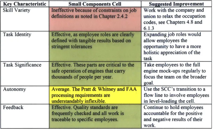
The following table summarizes how the Small Components Cell fares within each
category with a three-part scale (Effective, Average, Ineffective), as well as some brief
recommendations for change.
Key Characteristic Skill Variety
Task Identity
Su ested Im rovement Work with the company and union to relax the occupation codes, see Chapters 4.8 and
6.1.3
Expanding job roles would allow employees the opportunity to have a more holistic appreciation of the task
Task Significance Efetv.Teepit r rtclTake employees to the full
safeopeadenof ngins tet crryengine mock-ups regularly to thouand ofpeope pr yar.focus the team on the broader
goal.
Autonomy |Average. The Pratt & Whitney and FAA Use the SCC's transition to a
processing requirements are flow line to involve employees
understandably inflexible. in level-loading the cell.
Feedack f!NedveQuahy saniardsareContinue to hold employees
fteqenty ceckd en a#wor isaccountable for the positive tracableto setie enployes.and negative results of their
work.
Table 1: Performance comparison of the SCC to job design criteria.
Working to build upon these solid foundations will benefit the Small Components Cell by
improving employee morale. The increased flexibility and employee involvement in lean
optimization activities will be of tremendous benefit to the company as well. Chapters 4.8 and
6.1.3 discuss how training can improve employee capabilities. Of course, training and job design
are not the only ways to more effectively align employee goals with the company. Pratt &
Whitney has an incentive compensation plan for its salaried associates and management team
that effectively incentivizes these employees to meet and exceed the business targets that the
company establishes. Expanding this program to the hourly associates would be tremendously
beneficial in more effectively binding the teams together. This type of hourly incentive
compensation plan has already been implemented in several other Pratt & Whitney sites,
including locations with LAM-represented employees. A leadership team member notes that