Publisher’s version / Version de l'éditeur:
Vous avez des questions? Nous pouvons vous aider. Pour communiquer directement avec un auteur, consultez la première page de la revue dans laquelle son article a été publié afin de trouver ses coordonnées. Si vous n’arrivez pas à les repérer, communiquez avec nous à [email protected].
Questions? Contact the NRC Publications Archive team at
[email protected]. If you wish to email the authors directly, please see the first page of the publication for their contact information.
https://publications-cnrc.canada.ca/fra/droits
L’accès à ce site Web et l’utilisation de son contenu sont assujettis aux conditions présentées dans le site
LISEZ CES CONDITIONS ATTENTIVEMENT AVANT D’UTILISER CE SITE WEB.
Paper (National Research Council of Canada. Division of Building Research); no.
DBR-P-817, 1978
READ THESE TERMS AND CONDITIONS CAREFULLY BEFORE USING THIS WEBSITE. https://nrc-publications.canada.ca/eng/copyright
NRC Publications Archive Record / Notice des Archives des publications du CNRC :
https://nrc-publications.canada.ca/eng/view/object/?id=777c3eb9-a2d6-4081-86bb-0d21318e64e6 https://publications-cnrc.canada.ca/fra/voir/objet/?id=777c3eb9-a2d6-4081-86bb-0d21318e64e6
NRC Publications Archive
Archives des publications du CNRC
This publication could be one of several versions: author’s original, accepted manuscript or the publisher’s version. / La version de cette publication peut être l’une des suivantes : la version prépublication de l’auteur, la version acceptée du manuscrit ou la version de l’éditeur.
For the publisher’s version, please access the DOI link below./ Pour consulter la version de l’éditeur, utilisez le lien DOI ci-dessous.
https://doi.org/10.4224/40001681
Access and use of this website and the material on it are subject to the Terms and Conditions set forth at
Relationship between fire resistance and fire tolerance
,_ - - I Ser TH1 N21d no.
817
#& r L .c -
2National Research Council of Canada Conseil national de recherches du Canada
RELATIONSHIP BETWEEN FIRE RESISTANCE AND
FIRE TOLERANCE
'Ou- by T. Z. Harmathy
1 Reprinted from
Fire and Materials Vol. 2, No. 4, 1978
pp. 154-162
DBR Paper No. 817
Division of Building Research
Une grande partie de l'information recueillie au sujet de la rtsistance au feu des tltments stparateurs peut Ctre utilis6e dans la conception des bstiments rtaliste en fonction de la dcuritBincendie, si l'on convertit les valeurs de toltrance au feu en valeurs de rtsistance. Les mtthodes de conversion suivantes sont ttudites de f a ~ o n critique: la premikre est baste sur le concept des surfaces ayant les m&mes rapports temptrture-temps, la deuxi6me sur le concept des mCmes temptratures maximales et la troisi&me est baste sur la mtthode de Law; des instruments de conversion pratiques sont prtsentts dans cet article. En ce qui concerne les tltments porteurs des biitiments, il n'est pas recommand6 de fonder la conception du biitiment en fonction de la stcuritt-incendie sur l'information disponible sur la rtsistance au feu.
Relationship Between Fire Resistance and
Fire Tolerance?
T. Z. Harmathy
Fire Research Section, Division of Building Research, National Research Council of Canada, Ottawa, Canada, KIA OR6
Much of the information accumulated on the fire resistance of 'dividing' elements can be utilized in the design of buildings for fire safety, if the fire tolerance values are converted into fire resistances. Three methods of conversion, one based on the concept of equal temperature-time areas, the second on the concept of equal maximum tempera- tures, and the third, the Law method, are critically examined and handy conversion tools presented. In the case of the 'key' elements of buildings, basing the fire safety design on fire resistance information is not recommended.
INTRODUCTION
With the realization that fire resistant compartmentation may not be as effective a measure of protecting buildings against the spread of fire as previously thought, many fire scientists have become quite vocal about the need for a thorough revision of the existing fire protection practices. Yet progress toward new, knowledge-based fire protection practices seems to be very slow owing, possibly, to the fear that the multitude of data accu- mulated over the years on the fire resistance of building elements (as determined from standard fire tests) may be rendered useless by the new practices which, though logically coherent, will lack, for the time being, experi- mental foundations.
The purpose of this paper is to show that that fear is not justified; in fact, the bulk of the information available on the fire resistance of building elements may be well utilized in the newer concepts of providing fire safety in buildings.
FIRE SEVERITY PARAMETERS
The essence of these newer concepts is that the nature and extent of fire safety measures should be geared to the expected severity of potential fires.
It has long been usual to characterize the severity of compartment fires by their temperature histories for the postflashover period.1-3 Unfortunately this method of characterization is not fully justifiable, because it suggests that compartments with well in- sulated boundaries are liable to suffer fires of increased severity.
The author has suggested4-7 that the severity of compartment fires be characterized by the following three parameters: 1. the duration of fully developed fire, T ; 2. the overall penetration flux,
4,
i.e. the heatflux absorbed by the compartment boundaries, averaged spatially over the boundary surfaces and temporally
t
This paper is a contribution from the Division of Building Research, National Research Council of Canada and is published with the approval of the Director of the Division.over the period of full development; and 3. the average temperature of the compartment gases (average 'fire temperature'), Tg, averaged spatially over the compart- ment volume and temporally over the period of full development.
These parameters can be evaluated from simple calculations. 4-7
In examining the possible effect of fire on the various boundary elements of a compartment, the penetration fluxes for the individual boundaries are of interest. Noting that the over all penetration flux,
4,
depends on the material property group k / ~ l / ~ , interpreted aswhere
At =
C
Aii
and that the rate of heat absorption by the various boundary surfaces is proportional to ki/~il/', the pene- tration flux for the individual boundaries can be ex-
pressed as -
In Eqns (1)-(3) the subscript i (= 1, 2, 3,
. . .
) refers to the various boundary elements and their lining materials. After examining the import of the fire severity para- meters, it can be seen that of the three two are sufficient for uniquely characterizing a fire: the duration of fully developed fire, T, and the overall penetration flux,4.
In discussing the relation between the conventional and the newer concepts of providing fire safety, it may be necessary to select the average temperature of the compartment gases, Fg, instead of
4, as the mate
for T. It must be emphasized, however, that the selectionof
Tg
for characterizing the severity of a fire can be objected to on the same ground as the selection of the complete temperature history of the fire.It is convenient to define the nominal duration of the entire postflashover period (period of full development plus decay period) by multiplying T by an empirical
factor,
Tpf = AT (4)
h 21 1.15 is recommended for cellulosic materials and
RELATIONSHIP BETWEEN FIRE RESISTANCE A N D FIRE TOLERANCE
char-forming plastics. For non-charring plastics and the severity of fire exposure of the various boundary
liquid fuels h 2: 1. surfaces of a compartment in real-world fires, the
In summary, the three possible ways of characterizing question necessarily arises, how these qi compare with
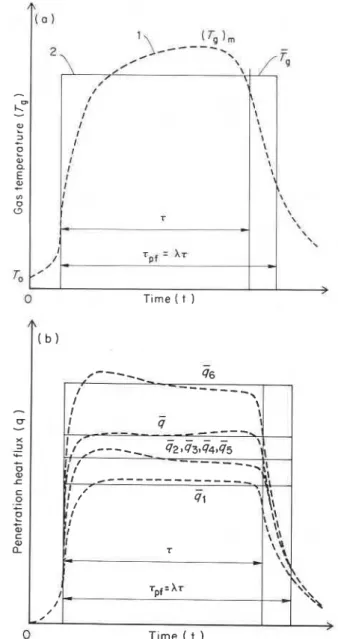
postflashover fires are illustrated in Fig. 1. Figure l a the (time-averaged) heat fluxes that penetrate these
shows the temperature-based characterization, either surfaces in standard fire resistance tests, (&)i((gr)l,
conventionally, by a fire-temperature versus time curve, (&)z, (qr)3,
.
..
). Some data reported by Seige18 andor by the fire severity parameters
Tg
and T. Figure l b the authorg showed that, as expected, the (qr)i dependdepicts the preferred method, characterization by largely on the thermal properties of the construction
and T, as well as by the individual penetration fluxes, material and on the duration of the test. Unfortunately
gl, g2, g3,
. .
.
applicable to the various elements of the they are known to depend also, in not readily quantifiablecompartment boundary. (It is seen that g, gl, 92, g3,
. . .
manners, on a number of other factors such as therepresent time-averaged values of quantities that are moisture content of the test specimen, the type of
subject to moderate variation.) furnace construction (especially the thermal properties
of the furnace lining materials), and the combustion and radiation characteristics of the burning furnace
PENETRATION FLUX IN FIRE TESTS fuel.
There have been a few attempts to evaluate experi-
If, as recommended, the penetration fluxes gi(41, 42, q3, mentally the rate of heat absorption by various con-
. . .
) are selected (in addition to T) for characterizing structions during standard fire resistance tests. Un- fortunately, the experimental difficulties have proved-
L"-
!?'-
z
0 a E a, + "7 o C3 TOA substantial. It seems, therefore, easier and perhaps
( 0 1 more accurate to estimate (qr)i from theoretical studies,
1 ( T 9 3m based on an acceptable model of heat transmission
2 I @
\I---
.
-
\ FQ between the furnace and the test specimen.
#
\ 1 In a multitude of computer simulations of fire re-
0 T~rne ( t ) the radiating medium (gases and furnace walls) as
perfect radiator; and (c) if the coefficient of heat transfer
/ / I I I I I I u
-
X 3 ! I \ I I I I,'
\ I / / -I'sistance tests, the author1O and Lie and Allenll modeled the 'standard' fire exposure as equivalent to the trans- mission of radiant heat to the specimen surface (whose emissivity was assumed to be about 0.9) from a black body whose temperature varied according to the tem- perature-time curve specified by ASTM Method El 19.
4 Although with this model the heat transfer by convection
i
t was neglected, it is believed that the error committed
\
x thereby was insignificant for the following reasons:
\ (a) the convective contribution to the heat transfer is
\
usually only a small fraction of the radiant heat transfer in most industrial furnaces;l2 (b) the neglect of con- vective heat transfer is compensated for by modeling
3 I I I I I r I I I t Tpf = AT -
LC ,,---,,- 42tq3t44145 sorption by the test specimen is usually negligible.
4-
----_
0 It is not surprising, therefore, that the described modeling
al
L
of
the furnace-to-specimen heat transmission in thec computer studies always yielded results comparable with
0
4-
e
I I those derivable from standard fire tests.+
al I I Some results taken from those computer studies have
C
2
been utilized in plotting in Fig. 2 the variation of the in-stantaneous penetration flux, (q,), (curves l a to 4a) as well \\
\\ as the average (over the period 0 to t) penetration flux,
I - T pf- - A T \\ \\ (&)i (curves 1 b to 4b), during standard fire resistance tests,
/
-
'\/ for four types of concretes; two normal weight (numbers 1
,
> and 2) and two lightweight (numbers 3 and 4). The four
0 Tlme ( t ) concretes are identified by the values of k i / ~ ~ l / ' (applic-
Figure 1 . Means of characterizing fire: (a) temperature-based able at room temperature) in the figure caption. These characterizat~on : curve I-by complete temperature versus values reveal that concretes 1 and 2 can be regarded, as far time curve; curve 2-by parameters Tg and 7. (b) Characteriza-
as performance in fire is concerned, as limiting cases for tion by parameters i j and T, and by the individual penetration
fluxes GI, Gz, Q3,
. . .
(the dashed curves represent the assumed weight and 3 and4aslimiting temporal variations of q, q l , qz, qs,. . .
). cases for lightweight concretes.10 Consequently, for0 Heyden & Son Ltd, 1978 FIRE AND MATERIALS, VOL. 2, NO. 4,1978 1 5 5
A
( b ) is high, higher than, say, 80 W m-2 K-1, the rate of heat absorption by a solid is controlled largely by
-
the group k i / ~ i " ~ and the magnitude of the coefficient..----
.-
46of
heat transfer is of secondary importance.1° Since,/ I - - - \ 1 I
-
I I J- -
4-_---
I I l # - - - \in the case of well-designed test furnaces, the coefficient of heat transfer by radiation alone is sufficiently high, the contribution of convection to the rate of heat ab-
T. Z. HARMATHY
T ~ m e Into the test t ( h )
Figure 2. Penetration heat fluxes during standard fire tests:
- instantaneous penetration fluxes; - - - - time-averaged
penetrafion fluxes; curves I a and I b : normal weight concrete, k i / ~ i ~ 1 ~ = 2 1 3 0 ; curves 2a and 2b : normal weight concrete k i / ~ i l / ~ = 1500; curves 3a and 3b : lightweight concrete, k i / ~ i ' l ~ = 7 8 0 ; curves 4a and 4b: lightweight concrete, k i / ~ i l / ~ = 500.
ordinary normal weight and lightweight constructions, realistic values of (&)i are expected to lie between curves l b and 2b, and 3b and 4b, respectively (lined areas in Fig. 2).
In tests of up to 1 h duration (&)i may be chosen
roughly as 27 500 W m-2 for normal weight, and as 15 000 W m-2 for light concrete constructions. For con- structions made of other materials, interpolation is per- missible based on the value of the property group k i / ~ i l / ~ . It may be added here that the thickness of the test specimen, unless unusually small, has no noticeable influence on the value of (qr)i.
FIRE RESISTANCE VERSUS FIRE TOLERANCE There are two problems intrinsic to the use of fire resistant compartmentation as a technique of fire defense: how to decide on what constitutes the minimum period of satisfactory performance of the compartment boundaries, and how to judge the acceptability of the boundaries for the specified performances.
With respect to the first problem, decisions on the minimum period of satisfactory performance are usually made authoritatively by the writers of building codes. As t o the latter, the common practice at present is to judge the acceptability of a compartment boundary for a specified minimum performance on the basis of its $re resistance, as determined, in general, by subjecting a representative specimen of the construction to a standard fire test, e.g. in North America the ASTM E l 19 test.
The practice of complying with authoritative decisions in choosing the minimum periods of satisfactory per- formance, t*, and identifying the periods of satisfactory performance with the fire resistance values, r, developed for the various constructions either by fire tests or by reasonings or calculations based on the fire test philo- sophy, will be referred to here as fire resistance allotment. Clearly, the condition of acceptability of a construction is
r r t * (=rmin) (5)
There are many advocates of the idea that competent engineers be given a larger degree of freedom in working out the most appropriate measures for the containment of possible fires. This greater freedom would include examination of the performance of the planned com- partment boundaries under the relevant conditions, and the making of decisions on their acceptability.
In contradistinction to fire resistance allotment, the practice involving decisions by qualified engineers on the necessary and adequate measures of fire containment will be referred to as $re tolerance design. The term
$re tolerance, to be denoted by 0, will be used in a
specific sense, to mean period of satisfactory per- formance of a building element under the applicable fire severity conditions (as characterized by qi, or,
less desirably, by
Tg),
determined by either engineeringstudies or by non-standard tests; the limit of satis- factory performance being defined (for reasons to be explained in the next section) either (a) by heat trans- mission and structural failure criteria, similar to those of the standard test methods, in the case of 'dividing elements' or (b) in the case of 'key elements', by the same criteria for fire exposure on one side or the other, but by structural failure criteria only for fire exposure on both sides.
The condition of acceptability is
Because of some basic faults behind the philosophy of fire resistance allotment,G the movement for the recognition of the fire tolerance design is steadily gaining momentum.
DIVIDING ELEMENTS AND KEY ELEMENTS In defining the meaning of fire tolerance, differentiation has been made between dividing and key elements from the point of view of the applicable failure cri- teria. The logical background for this differentiation is as follows.
The term dividing element is to be applied to those components of a building that are not essential parts of the principal structural network. Clearly, once the fire has reached, via any path, the reverse side of a dividing element, its structural failure (collapse) can in no way influence either the further course of the fire or the performance of the building as a whole. Conse- quently, the performance of a dividing element in fire can be evaluated on the assumption that the element is exposed to fire on one side only.
In contrast, the structural failure or major deforma- tion of the essential load-bearing elements, the so-called key elements, of a building may result in extensive damage and loss of life and, therefore, must not be allowed to happen even after an eventual spread of the fire to their reverse sides. Consequently, the performance of every key element of a building must be judged on the assumption of a two-sided fire exposure, provided that such exposure is conceivable and, if it is, that it represents an adverse situation.
It has been shown6 that the exposure of a construction to fire on both sides (not necessarily simultaneously) indeed creates a situation which is more adverse than that arising from a one-sided exposure. Since in a
RELATIONSHIP BETWEEN FIRE RESISTANCE AND FlRE TOLERANCE
standard fire test a construction is exposed to the test fire on one side only (except columns), there are funda- mental obstacles to the utilization of fire resistance data (derived from either fire tests or reasonings or calculations based on the fire test philosophy) in the design of key elements for fire safety. Obviously, such obstacles do not exist in the case of the dividing elements and, therefore, the utilization of fire resistance data in the design by dividing elements for fire safety is mainly a problem of convertibility between fire tolerance and fire resistance.
CONCEPT OF EQUAL TEMPERATURE-TIME AREAS (Method 1)
Kawagoe13 1 3 was the first to consider the problem
0
1
I'
t
0 0 5 1.0 1.5 Time ( h
Time ( h )
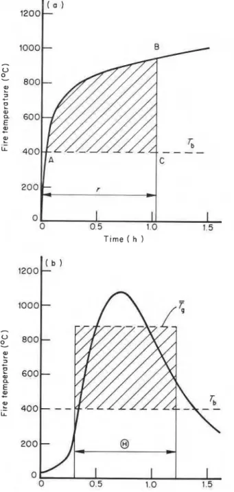
Figure 3. Concept of equal temperature-time areas: (a) standard fire test; (b) a real-world fire.
of utilization of fire resistance data in a rational fire tolerance design. Asserting that the severities of compart- ment fires can be characterized by their temperature versus time curves, he suggested that all fires, real- world fires as well as standard test fires, be compared on the basis of the area under their temperature history curves above a base level, Tb, 673 K (400 OC) for normal weight concrete and similar constructions, and 773 K (SOO°C) for lightweight concrete and similar construc- tions. This concept, as applied to the comparison of a standard test fire and a real-world fire, is illustrated in Fig. 3.
The following equation applies :
area (ABC) = (Tg - Tb)8 (7)
To bring this equation into tractable forms, it is neces- sary to express area (ABC) in terms of fire resistance, r, in other words, in terms of the time of successfully endured exposure to a test fire. To develop such expres- sions, two area (ABC) versus r plots have been prepared (corresponding to the two values of Tb; using the standard ASTM El19 furnace-temperature versus time curve) in Fig. 4. These curves seem to be amenable to approximation by straight lines and the following equations :
for Tb = 673 K area (ABC) = 555 (r
-
1000) (8) for Tb = 773 K area (ABC) = 444 (r - 1000) (9) By combining Eqns (8) and (9) with Eqn (7), two correlations are obtained between fire tolerance and fire resistance. They are, for normal weight concrete constructions and the like:for lightweight concrete constructions and the like:
These equations suggest that, from the point of view of fire resistance requirement, short and hot fires are equivalent to longer and relatively cool fires.
Figure 4. Temperature-time area versus fire resistance plots for standard ASTM E l 19 fire exposure, at t w o values of the base temperature. Dashed lines represent straight line approximations for the curves.
T. Z. HARMATHY
CONCEPT OF EQUAL MAXIMUM temperatures reached by a steel component of deciding
TEMPERATURES (Method 2) importance in real-world fires and standard test
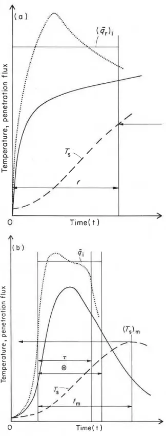
fires.14-1s The concept is illustrated in Fig. 5. For protected steel and reinforced or prestressed concrete
constructions the concept of equal maximum tempera- tures is a more realistic one. This concept states that the corresponding values of fire tolerance and fire resistance are those that pertain to identical maximum
To develop a relationship between fire tolerance and fire resistance, first the temperature of the crucial steel component, Ts (at a distance a below the surface of the concrete or other protective material) is to be expressed for the real-world fire with the air of the penetration flux. di. Because the maximum temnerature of that steel component is reached inevitabiy following the end of the nominal fire exposure? (Fig. 5b), only the t > 8 region of its temperature history is of interest. For this region,lg
(12) After differentiating with respect to t, and making dTs/dt equal to zero, an expression is obtained for the time, t,, at which the crucial steel component reaches its maximum temperature, (Ts)m2":
8
-
~ i t m - 1
-- -- t m (1 3)
2 ( ~ - & ) ~ n ( ~ - : )
By substituting into Eqn (12) sets of corresponding values of O/tm and obtained from Eqn (13), a relationship results between ki[(TS)m-To]/qia and ~ i t , / a ~ . This, again utilizing corresponding values of 8/tm and ~ ~ t ~ l a 2 , can be converted into a relationship
I I
>
between0
T ~ m e ( t ) ki[(Ts)m - TO] and ~ i 6-
&a a2
A
I b ) which is plotted as curve 1 in Fig. 6.
With test fires, as with real-world fires, the severity of fire exposure is more aptly characterized by the (average) penetration heat flux, (&)i, than by the standard temperature-time curve. Using (qr)i as datum informa-
X
3 tion, the temperature history of the same crucial steel
-
C C 0 1 - - .- t -F
-
- + 0) [I: 0 4-
a, - a-
7 0 2-z
3 tz
c , e 0 ' - 0) L Q 't EI -
F
0 04 --
0 02 - 0 01 ! 1 1 1 1 1 1 1 001 002 004 01 0 2 0 4 1 2 4 6 810>
K , @ ~ , r - - 0 T ~ m e ( t ) a2 ' 'aFigure 6. Information used in developing the relationship Figure 5. Concept of equal maximlum temperatures: (a) between fire resistance and fire tolerance.
standard fire test; (b) a real-world fire. - Fire temperature.
---- Temperature of a steel component of deciding importance. 't I t i s assumed that spalling or disintegration of the protective
.
. . . ..
Penetration heat flux. material is not liable to occur.RELATIONSHIP BETWEEN FIRE RESISTANCE AND FIRE TOLERANCE
component in a test fire is described by the following fire compartment, without resorting to the use of the equation : fire severity parameters. The method was worked out by Law and her colleagues in Britain.21-23 The following (14) empirical relationship was recommended :
But according to the concept of equal maximum tem- peratures, the standard fire resistance is interpreted as the time at which Ts attains the value (TS), in the corresponding real-world fire, i.e., t = r when Ts = (Ts)m
Thus, the concept of equal maximum temperatures is expressed by the equation
This equation defines a family of curves ki[(Ts)m - To] Kir
versus
,
qia awith qi/(&)i as a parameter. Two members of the family are also plotted in Fig. 6; one (curve 2a) for gi/(qr)i= l and the other (curve 2b) for ~ji/(&)~ = 2.
If complemented by further curves of the family, representing a spectrum of realistic values for gi/(&)i, Fig. 6 will offer a convenient way of graphically de- veloping a relationship between the fire resistance and fire tolerance in the following dimensionless form:
The procedure is illustrated in Fig. 6.
To find sets of corresponding values of ~ i B / a ~ and r/B for, say, gi/(qr)i=2, read ~ i B / a ~ and ~ i r / a ~ from curves 1 and 2b respectively, at various levels of the ordinate, ki[(Ts)m -To]/qia, then obtain r/B by dividing ~ i r / a ~ by KiB/a2.
Figure 7 is a graphical presentation of the relationship expressed by Eqn (16) for those ranges of the three variables which are important in the solution of practical problems.
LAW METHOD (Method 3)
It is also possible to calculate the minimum fire resistance requirements directly from the characteristics of the
This equation was later slightly modifiedz4 to include an additional variable, namely the height of window.
The Law method suggests that for a given compart- ment (i.e. for G = const and (At - AF) z const) the fire resistance requirement is inversely proportional to AwlI2, in other words, to the square root of rate of entry of air into the compartment. If one assumes that the minimum fire resistance requirement for a specific compartment boundary is roughly proportional to the product (referred to as the fire severity product by this authors), such a relationship indeed seems to be justifiable (see Fig. 9 in ref. 5). Unfortunately, com- bining g and T into a single fire severity parameter is not
strictly correct.
NUMERICAL EXAMPLES
The application of the preceding three methods will now be illustrated on two numerical examples. Both relate to a compartment similar to that used in the experiments of Butcher et a1.25, 26
Example 1
Information on compartment. Dimensional details:?
Fire load (cellulosic) : G = 436 kg, specific surface
of fuel
4
= 0.13 m2 kg-I. Average thermal propertiesof compartment lining materials: k = 0.616 W m-1 K-1,
~ = 0 . 3 2 6 x m2 s-l.
Characteristics of a potential fire. Fire severity para- meters from calculations4-7: T = 1162 s, 4 = 14 060 W m-2,
Tg
= 820 K. Required minimum fire tolerance period(for cellulosic fuel A = 1.15): Bmin=1.15 x 1162= 1336 s. Information on the structure to be protected. Rein- forced lightweight concrete ceiling slab. Thermal pro- perties: ki =0.62 W m-l K-I, ~i = 0.28 x 10⁻⁶ m2 s-1. Dis- tance of reinforcing bars from the fire exposed surface: a = 0.03 m.
Miscellaneous information. Pre-fire temperature :
TO = 293 K, estimated penetration heat flux in standard
fire test (for lightweight concrete) : (&)i = 15 000 W m-2.
Solutions. Method 1-based on the concept of equal temperature-time areas. Use Eqn (1 1)
Figure 7 . Dimensionless presentation of the relationship f Some of the variables listed here do not appear in any of the between fire resistance and fire tolerance using the concept of formulas presented in this paper; their values are needed, however,
equal maximum temperatures. in the calculation of the fire severity parameter^.^-^
T. Z. HARMATHY
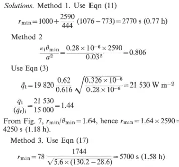
Method 2-based on the concept of equal maximum Solutions. Method 1. Use Eqn (11)
temperatures. Introductory calculations : 2590
rmin = lOOO+- (1076 - 773) = 2770 s (0.77 h) Kidmin-0.28 X lo-' X 1336 =0.416 444 - a 2 0.032 Method 2 Use Eqn (3) 0 62 z . 3 2 6 ~ 10-6 ~ i = 1 4 0 6 0 ~ 0.616 0.28 x 10-6 =15 270 W m-2 gi 15270-1.02 ai=15
-From Fig. 7, rmin/Omin= 1.40, hence rmin = 1.40 x 1336 =
1870 s (0.52 h).
Method 3-Law method. Use Eqn (17)
Example 2
Information on compartment. Same as in example 1, except that the fire load, G, is 1744 kg.
Characteristics of potential fire. Fire severity para-
meters from cal~ulations:~-7 T = 2250 s, g = 19 820
W m-2,
T,=
1076 K. Minimum fire tolerance periodrequired : Omin = 1.15 x 2250 = 2590 S.
Information on structure to be protected, and miscel- laneous information. Same as in example 1.
Use Eqn (3)
From Fig. 7, rmin/Omin = 1.64, hence rmin = 1.64 x 2590 =
4250 s (1.18 h).
Method 3. Use Eqn (17)
Discrepancies similar to, or even larger than, those occurring in the selected examples can be expected as normal.
DISCUSSION
The relative merits of the described three methods of conversion between fire tolerance and fire resistance can perhaps be best discussed in connection with the results of some additional calculations presented in
Table 1. Calculated fire resistance requirements for three reinforced concrete beams exposed to real-world compartment fires at three fire loads (cellulosic)&
(A) Fire severity parameters and related information
Specific Insulated compartment Non-insulated compartment fire load GIA F 7
-
Q T g 0-
Q i-
Qi T 4 T s e - Q i-
4i (kg m-2) (s) (W m - 9 (K) (s) (W m+) ( i r ) i (s) (W r 2 ) (K) (s) (W m-') (Qr)i 15 1162 1 0 1 6 8 782 1336 2 8 4 7 0 1 . 0 4 1162 1 1 442 754 1336 21 477 0 . 7 9 30 1162 2 2 6 4 9 1159 1336 6 3 4 1 7 2.31 1162 2 7 3 8 9 1065 1336 5 1 4 0 9 1 . 8 7 60 1910 23 532 1386 2197 65 870 2 . 4 0 1910 29 979 1268 2197 56 271 2 . 0 5(B) Miscellaneous input information and results for insulated compartment (IC) and non-insulated compartment (NIC) Specific Beam Fire resistance requirement consistent with fire tolerance design (h) fire load
GIA F Size a ~i e Method 1 Method 2 Method 3 Ref. 27b IC NIC IC 0.351 0 . 3 3 2 0.575 0.538 0.631 0 . 6 0 3 0 . 5 4 0 1 ,043 1.021 1.095 1 . 0 6 2 0 . 9 3 2 1.727 1 . 7 3 3 1.738 NIC 0 . 4 8 3 0.456 0.546 0 . 8 8 3 0 . 8 5 4 0.939 1 ,459 1 .446 1 ,483 IC NIC IC
" Information on compartment: A F = 12.43 m2, At=66.48 m2, Aw=2.58 m2, h=2.18 m, k / ~ l l ~ = 7 8 3 J s-lI2 m-z K-1 (insulated compart-
ment), k / ~ l J ~ = 1 1 6 8 J s-lI2 m-2 K-l (non-insulated compartment).
Information concerning the beams: ~ ~ = 0 . 5 8 7 ~ 10-6 m2 S-1, ki/Kif=2192 J S-112 m-2 K-1.
Penetration heat flux in standard fire test: (Gr)i=27 500 W m-2. Obtained by computer simulations of the fire processes.
RELATIONSHIP BETWEEN FIRE RESISTANCE AND FIRE TOLERANCE
Table 1. These calculations relate to the fire resistance requirements for three reinforced concrete beams under exposure to real-world compartment fires similar to those produced experimentally by Arnault et ~1.18 In their experiments they used three 'specific' fire loads
( G l A ~ = 1 5 , 30 and 60 kgm-2). While, in the series to be considered here, the compartment dimensions and ventilation were kept constant, the compartment lining materials were selected to represent two kinds of boundary conditions, namely-in the authors' words- 'insulated' and 'non-insulated' compartment boundaries.
All essential information concerning the compartment and the concrete beams is given in Table 1 . ( ~ h ~ m a t e r i a l properties have been estimated by the author on the basis of his own measurements performed on materials similar to those described in the Arnault et al.18 report.)
The fire severity parameters (calculations4-7) and some related information are given in section A of Table 1 ; the results are summarized in section B.
The following observations can be made: (1) Method 1, by utilizing the variables Q and
Tg,
is responsive to all those factors on which the severity of fire depends, such as fire load, ventilation, compartment dimensions, and compartment lining. It is responsive, in a crude way (by the selection of the appropriate base tempera-compartment dimensions, and compartment lining). By utilizing ~i and a, it is also responsive to the nature
of the construction considered, namely to its material and to the thickness of the protective cover on its crucial load-bearing component.
(3) Method 3, by depending on G, A w and At, is responsive to fire load, ventilation, and overall com- partment dimensions. It is not responsive either to the quality of compartment insulation, as determined by the thermal properties of the lining materials, or to the nature of the construction considered, as determined by its material and by the thickness of cover on its crucial load-bearing component.
These findings are summarized in Table 2. As to Method 3, the significance of not taking account of the nature of the construction considered (material and protective cover on the crucial load-bearing com- ponent) has not yet been investigated systematically. It is well known, however, from the experiments of Arnault et aZ.,l8 that the error resulting from neglecting the insulating quality of the compartment boundaries may be quite substantial.
Because it relies on the most realistic input information and on the use of a graph (Fig. 7) prepared without resort to empiricism, Method 2 should, as a rule, be
. ~
ture level, Tb) also to the nature of the material of the preferred over the other two methods.
construction considered. It is not responsive to the The results of several computer studies performed thickness of protective cover on the crucial load-bearing by Schneider and Haksever27-for the same beams component of the construction. and fire conditions (for 'insulated' compartment bound- (2) Method 2, by utilizing the variables B and @, aries only)-are also included in Table 1. It can be is responsive to all important characteristics of the seen that, except for the largest fire load, Method 2 compartment fire (as determined by fire load, ventilation, gives the best approximations.
Table 2. Characterization of three methods of conversion between fire tolerance and 6re resistance
Responsive to
Compartment characteristics Construction characteristics Thickness of Compartment Compartment protective Method Fire load Ventilation dimensions lining Material cover
1 Yes Yes Yes Yes 7 N o
2 Yes Yes Yes Yes Yes Yes 3 Yes Yes Yes N o N o N o
CONCLUSIONS information on performance of building elements under two-sided fire exposure, fire resistance information cannot be utilized in the design of such elements which As far as dividing elements are concerned, the available are relied upon for the integrity of the building even massive information on the fire resistance of building under two-sided exposure. The design of these key elements can be well utilized in the design for fire safety. elements must be based on special studies similar to Unfortunately, because standard fire tests do not yield those described in a previous paper.6
REFERENCES
1. K. Kawagoe and T. Sekine, BRI Occasional Report No. 17, Building Research Institute, Japan (1964).
2. S. E. Magnusson and S. Thelandersson, Acta Polytech. Scand., Civ. Eng. Build. Constr. Series No. 65, Stockholm (1 970).
3. T. T. Lie, Fire Technol. 10, 31 5 (1 974).
4. T. Z. Harmathy, Fire Technol. 12, 95, 21 9 (1 976). 5. T. Z. Harmathy, Fire Technol. 8, 196, 326 (1 972).
6. T. Z. Harmathy, Fire Res. 1, 11 9 (1 977178).
7. T. Z. Harmathy, Design to Cope with Fuily Developed Fires, ASTM Symposium on 'Design of Building for Fire Safety', Boston (June 1978).
8. L. G. Seigel, The Severity of Fires in Steel-Framed Buildings, Symposium No. 2, JFRO, HMSO, London, 57 (1968). 9. T. Z. Harmathy, Fire Technol. 5, 140 (1 969).
10. T. Z. Harmathy, ASTM Special Technical Publication No. 464, p 209. American Society for Testing and Materials, Philadelphia (1 970).
T. Z. HARMATHY
11. T. T. Lie and D. E. Allen, Techn. Paper No. 378, Div. Bldg. Res., Nat. Res. Counc. Canada (1 972).
12. W. Trinks and M. H. Mawhinney, Industrial Furnaces, Wiley, New York (1 961 ).
13. K. Kawagoe, Estimation of Fire Temperature-Time Curve i n Rooms, BRI Research Paper No. 29, Building Research Institute, Japan (1 967).
14. E. G. Butcher and M. Law, Comparison between Furnace Tests and Experimental Fires, Symposium No. 2, JFRO, H MSO, London, 45 (1 968).
15. H. Ehm and P. Arnault, Vorlaufiger Versuchsberight uber
Utersuchungen mit natiirlichen Branden, Europaische Kon- vention der Stahlbauverbande, Uterkommission 3.1 (October 1 969).
16. 0. Pettersson, The Possibilities of Predicting the Fire Behaviour of Structures on the Basis of Data from Standard Fire Resistance Tests, Centre Sci. Techn. Bbtiment, Colloque sur les Principes de la Securit6 au Feu des structures, Paris (2-4 June 1971 ).
17. 0. Pettersson, Fire Engineering Design of Tall Buildings, in Tall Buildings Criteria and Loading, Proceedings, Inter- national Conference Planning and Design of Tall Buildings, Bethlehem, Pa., USA (August 1972).
18. P. Arnault, H. Ehm and J. Kruppa, Rapport sur les Essais avec des Feux naturels Exbcutbs dans la petite Installation des Maisibres-16s-Metz, Doc. CECM 3-7318F. Centre Techn. Ind. Constr. Metallique, France (1 973).
19. H. S. Carslaw and J. C. Jaeger, Conduction of Heat in
Solids, 2nd Edn, p 76. Clarendon Press, Oxford (1959). 20. T. 2. Harmathy, J. Appl. Phys. 35, 11 90 (1 964).
21. P. H. Thomas, Fire Res. Note 901, JFRO (1971). 22. M. Law, Fire Res. Note No. 877, JFRO (1 971).
23. M. Law, Prediction of Fire Resistance Symposium No. 5, JFRO, HMSO, London, 1 6 (1973).
24. 0. Pettersson, Fire Safety in Constructional Steel-work, Chapter 2, CECM, 111-74-2E (1974).
25. E. G. Butcher, T. B. Chitty and L. A. Ashton, Fire Res. Techn. Paper No. 15, JFRO (1966).
26. E. G. Butcher, G. K. Bedford and P. J. Fardell, Further
Experiments on Temperatures Reached by Steel in Buildings
Symposium No. 2, JFRO, HMSO, London, 1 (1968). 27. U. Schneider and A. Haksever, Bestimmung der aquivalenten
Branddauer von statisch bestimmt gelagerten Stahlbeton- balken bei naturlichen Branden, lnstitut fur Baustoffkunde und Stahlbetonbau der Technischen Universitat Braun- schweig (December 1976).
Received 12 June 1978 Heyden & Son Ltd, 1978
APPENDIX I : NOMENCLATURE a A G h H i ierfc k
distance of steel from fire-exposed surface, (m) area (m2)
total fire load (kg) height of window (m) height (m)
=1, 2, 3 , .
.
.
integral of the error function of
thermal conductivity ; without subscript : average thermal conductivity (W m-l K-l)
penetration heat flux (W m-2)
temporal average penetration heat flux either during the fully developed period of real-world fires or during standard test fires; without subscript: that averaged spatially for all com- partment boundaries; with subscript: that for an individual compartment boundary (W m-2) fire resistance (s)
time (s)
authoritatively specified minimum period of satisfactory performance (s)
temperature (K)
average temperature during the fully developed period of real-world fires (K)
fire tolerance (s)
K thermal diffusivity ; without subscript: average
thermal diffusivity (m2 s-1)
h factor (Eqn (4)), cz 1, 1.15, dimensionIess
T fire duration; without subscript: that of fully
developed fire; with subscript: nominal fire duration (s)
specific surface of combustibles (m2 kg-1) Subscripts m min 0 P f r S t W of base level of compartment of floor of compartment gases
for the ith boundary element and its lining material
maximum minimum
under pre-fire conditions for the postflashover period
under standard fire resistance test conditions of steel
total for the compartment of window