Publisher’s version / Version de l'éditeur:
Vous avez des questions? Nous pouvons vous aider. Pour communiquer directement avec un auteur, consultez la première page de la revue dans laquelle son article a été publié afin de trouver ses coordonnées. Si vous n’arrivez pas à les repérer, communiquez avec nous à [email protected].
Questions? Contact the NRC Publications Archive team at
[email protected]. If you wish to email the authors directly, please see the first page of the publication for their contact information.
https://publications-cnrc.canada.ca/fra/droits
L’accès à ce site Web et l’utilisation de son contenu sont assujettis aux conditions présentées dans le site
LISEZ CES CONDITIONS ATTENTIVEMENT AVANT D’UTILISER CE SITE WEB.
Paper (National Research Council of Canada. Division of Building Research); no.
DBR-P-1022, 1981
READ THESE TERMS AND CONDITIONS CAREFULLY BEFORE USING THIS WEBSITE. https://nrc-publications.canada.ca/eng/copyright
NRC Publications Archive Record / Notice des Archives des publications du CNRC : https://nrc-publications.canada.ca/eng/view/object/?id=897f00d5-331f-446f-8199-6ca24a868bc7 https://publications-cnrc.canada.ca/fra/voir/objet/?id=897f00d5-331f-446f-8199-6ca24a868bc7
NRC Publications Archive
Archives des publications du CNRC
This publication could be one of several versions: author’s original, accepted manuscript or the publisher’s version. / La version de cette publication peut être l’une des suivantes : la version prépublication de l’auteur, la version acceptée du manuscrit ou la version de l’éditeur.
For the publisher’s version, please access the DOI link below./ Pour consulter la version de l’éditeur, utilisez le lien DOI ci-dessous.
https://doi.org/10.4224/40001699
Access and use of this website and the material on it are subject to the Terms and Conditions set forth at
The fire resistance test and its relation to real-world fires
Ser
THI
N21d
no.
1022National Research
Conseil national
C . 2
I
*
Council Canada
de recherche Canada
THE FIRE RESISTANCE TEST AND ITS RELATION
TO REAL-WORLD FIRES
by T .
Z.Harmathy
A~
ALYZE?
Reprinted f r o m
F i r e and Materials
Vol. 5, No.
3,1981
--
- -___c__Iu -%
p. 112
-
122
"' P,PRES,
I I12:'rARY
I! ' % 3 & 3 ~ 1 o " i k . i ~ ~ ~ ~
.
..?ec:b. € 3 2 ; ~ .
1 C N R C-
I c . I L ? T-
DBR P a p e r No. 1022
D i v i s i o n of Building R e s e a r c h
P r i c e $ 1 . 2 5
OTTAWA
NRCC 20009
SOMMAI RE
Cn 6 t u d i e les c a r a c t 6 r i s t i q u e s d e s f o u r s d ' e s s a i s . On montre q u e l e rendement d ' u n f o u r , rnesur6 e n terms d e l a c h a r g e thermique q u ' i l impose 5 1 1 6 c h a n t i l l o n , d6pend beaucoup de s a t a i l l e e t d e l a n a t u r e du gaz q u i s ' y t r o u v e . S e u l l e s g r o s f o u r s c h a u f f 6 s a u moyen de gaz rayonnant considCrablement ( s e r a p p r o c h a n t du c o r p s n o i r ) p e r m e t t e n t d ' o b t e n i r d e s r 6 s u l t a t s v a l a b l e s e t r e p r o d u i s i b - l e s . Le remplacement de l a g a r n i t u r e d ' u n f o u r d 6 f e c t u e u x p a r un m a t 6 r i a u de t r S s f a i b l e i n e r t i e t h e r m i q u e e s t c e r t e s u t i l e mais n e s u f f i r a probablement pas 2 ramener l e rendement du f o u r au n i v e a u voulu. On e s q u i s s e l e s d t h o d e s d e d 6 t e r m i n a t i o n du rendement d e s f o u r s d ' e s s a i s . Le th6orSme de 1 1 u n i f o r m i t 6 d e l a c h a r g e t h e r - mique normalis6e est de v a l i d i t 6 s a t i s f a i s a n t e pour a p p l i c a t i o n aux f e u x compartiment6s r C e l s . On r e c o n n a f t l a c h a r g e t h e r m i q u e n o r m a l i s 6 e comme d e s c r i p t e u r s u c c i n c t du p o t e n t i e l d e s t r u c t e u r d e s feux. Ce d e s c r i p t e u r forme donc l a b a s e de l a c o r r 6 l a t i o n d e s f e u x d ' e s s a i s aux f e u x r 6 e l s .
The Fire Resistance Test
and its Relation to
Real-world Fires
ANALYZED
T. Z. Harmathy
Fire Research Section, Division of Building Research, National Research Council of Canada, Ottawa KIA 0R6, Canada
The characteristics of fire resistance test furnaces are examined. It is shown that the efficiency of a furnace, as measured in terms of the heat load it imposes on a test specimen, depends markedly on the size of the furnace and the nature of the furnace gas. Only with large furnaces heated by gases of high radiation potential (near-black gases) can the test results be regarded as meaningful and reproducible. Relining a defective furnace with a material of very low thermal inertia, though helpful, is unlikely to bring its performance up to the required level. Methods of determining the efficiency of test furnaces are outlined. The theorem of uniformity of normalized heat load is of satisfactory validity when applied to real-world compartment fires. The normalized heat load is recognized as a succinct descriptor of 6res with respect to their destructive potential. AS such, it forms the basis for correlating real-world fires with standard test firs.
INTRODUCTION
Advance in the rational design of buildings for structural safety in fires has long been hampered by the lack of insight into the relation between real-world compart- ment fires and standard test fires with respect to their destructive potential. The author called attention earlier1 to the fact that the 'heat load' on a building element, i.e. the heat absorbed by the element per unit surface area during the fire exposure, is the basis on which the destructive potential of real-world fires and test fires can be compared.
Ascertaining the heat load that real-world fires are expected to impose on the boundary elements of a compartment presents no problem, as has been shown by the author in several papers, most recently in Ref. 2. This last mentioned paper also presented, witl+iout giving details of the underlying considerations, a graph from which the heat load on any building element in a standard test fire could be determined. The validity of the information contained in that graph and possible limitations of its use will now be examined within the framework of a wide-ranging scrutiny of fire resistance tests and test furnaces.
Understanding how the design and operation of fire resistance test furnaces may affect the test results has been given a new urgency with a decision by ASTM Committee E05 that test standard El19 be reviewed in the light of up-to-date knowledge and be completely rewritten if necessary. Interest in unraveling the complex processes that evolve in a test furnace during a test is by no means new, as manifested by a number of papers written on the subject.3-8 The last referenced paper, that by Paulsen and H a d ~ i g , ~ is a particularly valuable contribution and can serve as a model for theoretical studies of the operation of fire test furnaces.
Because the fire test process is the main concern of
this study, the object of the investigation will usually b e .
' referred to as 'test furnace'. Yet there is clearly no
difference between a test fire and a real-world com- partment fire that could not be taken into account by the appropriate specification of the input variables. One can expect, therefore, that the conclusions reached will allow substantial generalizations.
THE THEOREM OF UNIFORMITY OF NORMALIZED HEAT LOAD
Although the concept of normalized heat load has already been outlined elsewhere (e.g. in Ref. 2), because of its great importance a brief account of the concept will be given here.
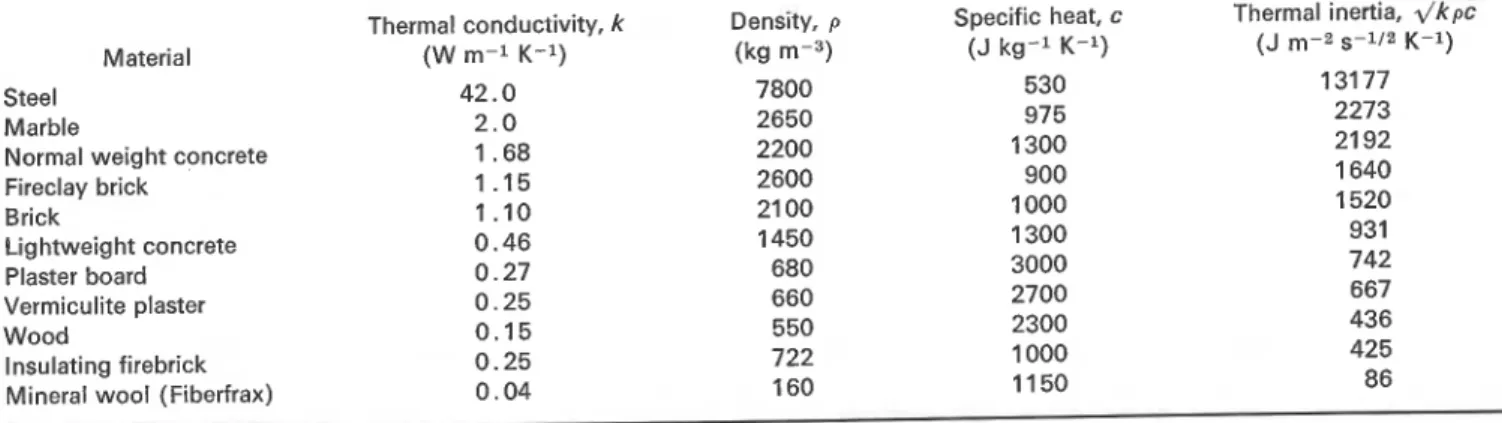
The heat absorbed by a test furnace or a compart- ment during a fire (test or real-world) depends on the thermal inertia, the group .\/Fc, of the boundaries. Here k is thermal conductivity, p density and c specific heat. If the various boundary elements are formed by different materials, . \ / c c represents the overall thermal inertia which is the weighted average of the thermal inertias for the individual boundary elements. For a furnace or compartment composed of n boundary elements,
1 n
where
and the subscript i (= 1, 2,
.
.
.,
n) refers to the various surface-forming materials, as well as the boundary surfaces formed by them. Typical values for the thermal properties of the most common construction materials are listed in Table 1.03084501/81/00054112 $05.50
112 FIRE A N D MATERIALS, VOL. 5, NO. 3, 1981
0
Heyden & Son Ltd, 19812
I,-:
;'-re
-
1 2 ,THE FIRE RESISTANCE TEST AND ITS RELATION TO REAL-WORLD FIRES
Table 1. Typical values of the thermal properties of common construction materials (in moistureless condition) for the appropriate temperature intervals
Material Steel
Marble
i
Normal weight concreteFireclay brick
1
Brick Lightweight concrete/
Plaster board-
Vermiculite plaster Wood Insulating firebrick Mineral wool (Fiberfrax)Thermal conductivity, k (W m-1 K-1) 42.0 2.0 1.68 1 .I5 1.10 0.46 0.27 0.25 0.15 0.25 0.04 Density, p (kg m-3) 7800 2650 2200 2600 21 00 1450 680 660 550 722 160 Specific heat, c (J kg-l K-l) 530 975 1300 900 1000 1300 3000 2700 2300 1000 1 1 50 Thermal inertia, .\/k% (J m-2 s-112 K-1 ) 131 77 2273 21 92 1 640 1520 931 742 667 436 425 86
The heat load on an ith boundary element, &T, is defined as
qi.
=J;
9idt (3)where qi and qi are the instantaneous and average values of the heat flux penetrating that element, respec- tively, t is time, and T is the duration of the fire. The overall heat load on the furnace chamber or compart- ment, @, can be expressed, analogously to Eqn (I), as the weighted average of the heat loads on the individual boundary elements:
1
47'-
X
A&)At i=l (4)
After multiplying Eqn (1) by @/.\/Fc and deducting the result from Eqn (4), a homogeneous linear equation is obtained the trivial solution of which can be written in the following form :
Each term in this multiple equation will be referred to as normalized heat load. Equation (5) is an expression of the claim that the normalized heat load is the same on all boundary elements, and is, in addition, equal to the normalized overall heat load. Clearly, the normalized overall heat load contains information related only to the fire compartment or test furnace as a whole and can be viewed therefore as the succinct quantitative descriptor of the fire itself.
Naturally, the homogeneous linear equation derived by combining Eqns (1) and (4) may also have non-trivial solutions; it remains to be seen, therefore, whether the trivial solution, which gives rise to the theorem of the uniformity of normalized heat load, is the one favoured by fire-related processes.
HEAT TRANSMISSION IN THE TEST FURNACE
In studying the heat transmission in fire test furnaces, the mathematical model described by Eckert and Drake9 for radiative heat exchange inside an enclosure will be used. This model has been built on the following
assumptions :
(a) All boundary surfaces that form the furnace chamber are spectrally gray; hence their total absorptivities are identical with their total emis- sivities, E .
(b) The temperature is constant over each separately considered surface element.
(c) The hot furnace gas is also gray, and therefore its absorptivity is identical with its emissivity,
n.
(d) The temperature of the furnace gas is uniformthroughout the furnace chamber.
(e) All heat transfer in the furnace chamber takes place by radiation only.
These widely used simplifying assumptions will be supplemented here by a few others:
1. The boundary surfaces of the furnace chamber are formed by two materials only, the material of the furnace walls and that of the test specimen. 2. Both the furnace walls and the test specimen are
homogeneous and sufficiently thick to allow the assumption that they are semi-infinite solids. 3. The emissivities for both materials are approxi-
mately equal and independent of the temperature. 4. The emissivity (or absorptivity, and transmissivity)
of the furnace gas is independent of the temperature. 5. The temperature of the furnace gas follows the standard temperature-time curve of ASTM E l 19. Most of these are routine assumptions. After learning the results of this study, the reader may reflect on these assumptions and will, no doubt, find that they cannot possibly influence the principal conclusions. Three of them, however, namely assumptions (e), (2) and (5), require further elaboration.
Assumption (e) implies that the convective contribu- tion to the heat exchange in the furnace chamber is negligible in comparison with the radiative contribution. The author chose to neglect convective heat transfer, not so much to reduce the labour of calculations as to avoid the problem of introducing an additional input variable the magnitude of which is difficult to assess. That the neglect of convective heat transfer will not influence the final conclusions to any appreciable degree, can be understood from the work of Harmathy and Blanchardlo on the temperature history of slabs heated on one side. It appears that if the Nusselt number, the
I
0
Heyden & Son Ltd, 1981
I
T. 2. HARMATHY group hllk, for the heated side of the slab (where h is
the heat transfer coefficient, I the thickness of the slab, and k the thermal conductivity of the slab material) is larger than about 10, the actual magnitude of the Nusselt number, and thereby of the heat transfer co- efficient, h, has hardly any effect on the rate of heat penetration into the slab. The explanation is straight- forward: as the supply of heat to the slab surface (as characterized by h) increases, the absorption of heat by the sIab becomes controlled more and more by the ability of the slab to conduct the heat away from its surface (as characterized by k).
On surveying the values given in Table 1, one finds that the thermal conductivity of normal weight concrete is just about the highest among the commonly used building materials : k = 1.68 W m-I K-l. Assuming that the slab is at least 0.2 m thick, the critical value of the heat transfer coefficient comes out to about 85 W m-2 K-1. In full-scale fire tests a heat transfer coefficient of that magnitude is usually reached within 10 min into the test by radiative heat transfer alone. Those who wish to compensate for the slight error resulting from the neglect of heat transmission by convection may do so by selecting for the absorption coefficient for the furnace gas (to be defined later) a n 'effective' value somewhat on the high side.
with regard to assumption (2), the possible non- homogeneity of either the furnace walls or the test specimen can be taken into account by the use of appropriate notional values for their thermal properties. For fire tests of up to 2 h duration, the fact that the furnace walls and the test specimen are of finite thickness rarely has any effect on the heat load on these boundary elements.
The third assumption that deserves consideration, assumption (5), is that the temperature of the furnace gas follows the standard temperature-time curve of ASTM E119. In reality, it is not the temperature of the furnace gas that follows the standard curve, but the temperature value obtained by averaging the readings from nine thermocouples enclosed in protective tubes. This so-called 'furnace temperature' depends on several factors such as the radiation potential of the furnace gas, the size and material of the furnace, the material of the test specimen, and the time constant for the furnace thermocouples.ll The true temperature of the furnace gas is higher than that prescribed at any time by the standard. As will be discussed later, this discrepancy can,
again, be compensated for by specifying an upward adjusted eKecttive value for the absorption coefficient for the furnace ras.
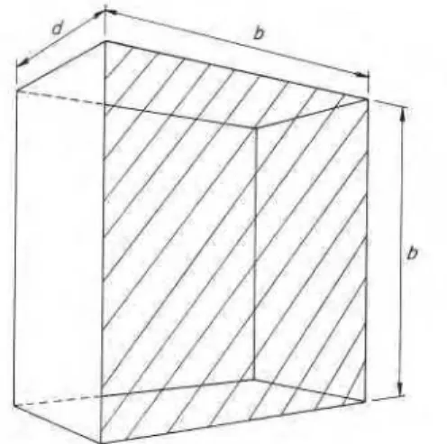
The geometry of the furnace chamber to be studied is illustrated in Fig. 1. To keep down the number of geo- metric variables, the furnace is modeled as a rectangular parallelepiped, with two of its dimensions taken as equal. Adopting the procedure described by Eckert and Drake9 to the designated conditions, the following two equations will result for the radiative heat exchange in the furnace chamber :
where, in preparation for a numerical follow-up techni- que, a superscript j (=O, 1,2,3,
. .
.) has been affixed to allFigure 1. Geometry of furnace chamber (lined area : test speci- men). Surface area of test specimen A1=b2; surface area of furnace Az=b2f 4bd.
variables that are functions of time. The superscript j indicates that those variables are to be considered at a time level t=jAt, where At is a preselected time incre- ment. The subscripts 1 and 2 refer to the two solid materials that form the boundary surfaces of the furnace chamber, namely the test specimen and the furnace walls, respectively, as well as to the surfaces formed by them. B1 and B2 are radiative heat fluxes leaving sur- faces 1 and 2, respectively; Fl1, FIB, F 2 1 and F22 are geometric factors, the so-called configuration factors, that relate to the direct radiation interchange between the surfaces indicated by the two subscripts; yll, y12, 7 2 1 and y22 are the transmissivities of the furnace gas between the surfaces indicated by the two subscripts; egl and cg2 are the emissivities of the gas into surfaces 1 and 2, respectively; Tg is the temperature of the furnace gas; ql and 9% are the heat fluxes absorbed by surfaces 1 and 2, respectively; and u is the Stefan-Boltzmann constant.
The fluxes absorbed by surfaces 1 and 2 can be expres- sed in two ways: first in terms of the radiative heat fluxes leaving these surfaces,
and second, in terms of the subsurface temperature gradients,
In Eqns (8)-(1 I), TI)^ and (T2)o are the temperatures of surfaces 1 and 2, respectively, (T1)l and (T2)l are tempera- tures at Axl and Axa distances below surfaces 1 and 2, respectively, and kl and k2 are thermal conductivities of the two solids, respectively.
Since, according to Fig. 1, surface 1 cannot 'see' any part of itself,
Fl1= 0 (12)
THE FIRE RESISTANCE TEST A N D ITS RELATION TO REAL-WORLD FIRES According to the teaching of the flux algebra, the other
three configuration factors are obtained as
Equation (12) also implies that
To the other three transmissivities the following equa-
.
tions are applicable :ylz = exp (a
-
LIZ) = exp (- ~ L z I ) = yzi (17)y22 = exp (- aL22) (18) where ol is the absorption (or emission) coefficient for the
(gray) furnace gas (a measure of its radiation potential), and LIZ (=L21) and La:! are the mean beam lengths for radiation between the surfaces indicated by the subscripts. By combining Eqns (14-30) and (14-31) of Eckert and Drake,g an equation can be obtained for the E,'S that,
when applied to the present conditions, yields
With the aid of Eqns (8)-(ll), the B's and q's can be eliminated from Eqns (6) and (7) and two simultaneous equations obtained, quartic in TI)^ and (Tz)o:
1 2 1 T TI)^^]^ + I 2 2 [(T2)oiI4
+
Jzi(Ti)oi+
J22(Tz)oj+ Kzj = 0The coefficients are as follows: (22)
Ill = 0 (23)
I 1 2 =
-
uy12 (24)1
where the P's, y's and 6,'s have not been detailed out forI
brevity.It was stipulated earlier that the temperature of the furnace gas, Tg, follows the temperature-time curve of ASTM El 19. An analytical approximation of that curve is
Tgj=293.2+ 750 (1
-
exp(- 0.063261/jt))+
2.8402y"jt (33) As stated earlier, (T1)l and ( T z ) ~ are the temperatures at some (reasonably small) Ax1 and Ax2 distances, respectively, below the surface of the two surface-forming solids: material 1 (test specimen) and material 2 (furnace walls). To obtain information on their values, the tempera- ture distribution in the two solids must be monitored by a numerical follow-up technique, e.g. by the finite difference method. This method will provide information on the variation of the temperature at a number of preselected points inside the two materials, located from the surface at distances x1=0, Axl, 2Ax1,.
.
. ,
iAx1,. . .
, nAxl for the test specimen, and at xz=O, Ax2, 2Ax2,.
. .
, iAxz,.
.
. ,
nAxz for the furnace walls. If the temperatures at all these points, i.e. all (T1)i7s and (T2)i9s, are known at a time level t=jAt, their values at the next time level, t = ( j + l)At, can be calculated from the following well-known equations (reproduced here only for the convenience of the reader):where i= 1, 2, 3,
. .
.
,
n- 1, and p and c are the density and specific heat, respectively, of the material indicated by the subscript.On practical considerations, it is permissible to place the nth (deepest) point at some finite distance, about 0.10-0.25 m from the surface. To fulfil the stability criterion for the calculation, At should be selected as
At,<
/
whichever is Iess (36)The procedure for solving Eqns (21) and (22) for (T1)obnd (T2)oj begins with defining the initial tempera- ture distribution (that at the j= 0 time level) in materials 1 and 2. As a rule, all points are assumed to be initially at room temperature :
By the time t = At, Tg will acquire a value Tgl according
to Eqn (33), but the penetration of heat will not have reached the points xl= Ax1 and xz= AX^; thus, both (T1)l1 and (T2)11 are still at 293.2 K. With these values Kll and Kzl can be calculated (in addition to the I's and J's which are not dependent on the time level; Eqns (23)-(32)), and thus Eqns (21) and (22) made ready to be solved for (T1)ol and (T2)ol. The solution can be achieved by Newton's iterative technique.12 If (TI), and (Tz), are approximate roots of Eqns (21)
T. Z. HARMATHY
and (22) (the previously applied subscripts and super- scripts are omitted to avoid confusion), better approxima- tions, (Tl),+l and (Tz),+l, can be reached by the applica- tion of the following formulas :
ah
afi
(Tl)v+l= (TI), -
afi
ah
afl
ah
(39)aT,
G
-
ar,
aT,
(Tl),, (T2)"provided that the denominator (Jacobian determinant) is not equal to zero. In these equations,fi and f2 symbolize
the polynomials on the left side of Eqns (21) and (22), respectively. The iteration is carried on until both (Tl),+l- (TI), and (Tz),+l- (T2), become less than a satisfactorily small value.
For the calculation of the entire process, only one pair of temperature values has to be estimated in advance, (T1)o1 and (T2)01, i.e. the surface temperature of the two solids at the time level t = At. For any other time level, t=jAt, the values (T1)of-1 and (T2)oj-1 can be used as first approximations for (T1)oj and (T2)oj.
Once (T1)oj and (T2)oj are known, the temperature distribution in the two solids at the time level t = ( j + I)At, i.e. temperatures (T1)ljt1, (T1)zjt1,
. . .
,
(TI),-IJ+~, (T2)ljt1, (T2)23+l,. .
. ,
( T ~ ) ~ - l j + l , can be calculated by repeated application of Eqns (34) and (35), and thus a new pair of values, (Tl)lf+l and (Tz)lj+l, will be available which, together with Tgj+l (Eqn (33)), will serve first for the calculation of K1ff1 and Kzj+l (Eqns (27) and (28)), and then, by successive iteration, of the tempera- tures (TI)o~+ 1 and (Tz)ojtl (Eqns (21), (22), (39) and (40)).The principal purpose of the calculations is, of course, to ascertain the variation, with the time of fire exvosure, of the heat load on the test specimen and perhaps alsd on the furnace walls. Knowing (Tl)oj, (Tl)lj, (Tz)oj and (T2)1j, the instantaneous values of the heat fluxes penetrating the furnace boundaries, qlj and qzj, can be expressed from Eqns (10) and (1 1). Then the normalized heat loads as functions of the length of fire exposure, T, are obtained as
where TrjAt, and (q1)~,3-1 and are the average
values of ql and 92, respectively, for the period 0 Q t Q (j- 1)At. Naturally, ( q ~ ) , , ~ = ( q ~ ) ~ ~ ~ = 0.
HEATING WITH BLACK GASES
If the absorption coefficient for the gas is sufficiently high, yll= y12 = y21= y22 = 0 and = ~2 = 1 according to Eqns (16)-(20). Gases with zero transmissivity are referred to as 'black gases'. An examination will reveal that if the test furnace is heated by a black gas, Eqns (6) and (7) become decoupled and fall apart into two
independent equations. (The reader may prove to him- self that similar decoupling will occur irrespective of the complexity of the heat transmission model.) By combining Eqns (6) and (8), and Eqns (7) and (9), one will obtain for the absorbed heat fluxes:
It appears, therefore, that if the furnace gas is 'reasonably black', the heat transmission takes place as if each individual surface were heated separately by radiation from a black body whose temperature follows the pre- scribed standard temperature-time curve. It may be of interest to note that this way of modeling of the heat transfer process has long been used by the author13 and by Lie and Harmathy14 in their studies on the behaviour of building elements in standard fire tests.
The numerical solution of Eqn (43) (or Eqn (44), the subscripts 1 and 2 can obviously be omitted) presents no difficulties. It can be shown that an expression developed by Carslaw and Jaeger (Eqn (11-9) in Ref. 15) for the surface temperature of a solid that absorbs heat at a (variable) rate q, can be represented by the following finite-difference form approximation :
In this equation, qj-" is the heat flux that penetrates the solid at a time t=(j-m)At. (This equation obviously assumes the knowledge of the heat flux at t=O, At, 2At,
. .
.,
( j - 1)At.) The heat flux at the level t=jAt, qf, can now be calculated using Eqn (43) (or (44)), and with that Toj+l from Eqn (45) in which, of course, all-j's must be replaced by ( j + 1)'s. Finally, the normalized heat load on the boundary elements of the furnace chamber, as a function of time of fire exposure, is obtained by the application of Eqn (41) (or (42)).RESULTS OF NUMERICAL STUDIES
In all numerical studies a fixed value, 0.9, was assigned to the emissivity of all surface-forming materials, a value which, according to a tabulation by McAdams,lG seemed to be a good average for building materials. The input information used in the studies is listed in Table 2. The mean beam lengths to be used in Eqns (17) and (18) were calculated from the furnace dimensions, and are listed in Table 3. It is believed that the selected input data cover a sufficiently wide range to allow valid generalizations.
The absorption coefficient for the furnace gas is a very elusive piece of information. It depends partly on the composition of the gas, and partly on its soot con- centration, and thereby it is influenced not only by the nature of the heating fuel but also by such factors as the type of burner, excess air or fuel, gas temperature, etc.l7*
Presented in Fig. 2 are some temperature records obtained during a standard fire resistance test performed to determine the actual and 'effective' values of the absorption coefficient for the furnace gas in the propane- heated floor furnace of the author's laboratory. The
THE FIRE RESISTANCE TEST AND ITS RELATION TO REAL-WORLD FIRES
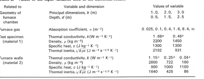
Table 2. Values of the input variables used in the numerical studies
Related to Variable and dimension Geometry of Principal dimensions, b (m)
furnace Depth, d (m) chamber
Values of variable 1.0, 2.0, 3 . 0 0.5, 1.5, 2 . 5 Furnace gas Absorption codfficient, a (m-l) 0.025,0.1,0.4, 1 .6,6.4,co
Test specimen Thermal conductivity, k ( W m - l K-l) (material 1) Density, p (kg m-3)
Specific heat, c ( J k g - l K-l)
Thermal inertia,z/kpc ( J m-2 s-lI2 K-l) Furnace walls Thermal conductivity, k (W m - l K-l)
(material 2) Density, p (kg m-3) Specific heat, c (J k g - l K-l)
Thermal i n e r t i a . 4 6 ~ (J m-2 s-lI2 K-l)
a Normal weight concrete. b Lightweight concrete. c Firelay brick. d Insulating firebrick. Mineral wool.
Table 3. Mean beam lengths, LIZ and LZZ, for selected values o f b andd d 0 . 5 1 . 5 2 . 5 1 L l z 0.494 0.737 0.804 Lzz 0.505 0.750 0.837 b 2 Liz 0.653 1.196 1 ,399 Lzz 0.700 1 .202 1 .432 3 Liz 0.726 1 ,481 1 .872 Lzz 0.828 1.517 1.879 Courtesy: Professor S. Hadvig.
furnace chamber was formed by mineral wool (Fiber- frax) on five sides and by insulating firebrick on one. The curve running highest, curve 1, represents the more or less true temperature of the gas, obtained by averaging readings from two aspirated thermocouples.lg The next curve, curve 2, is the nominal 'furnace temperature', arrived at by averaging readings from nine tube-pro- tected thermocouples, built and distributed according to standard E119. The lowest-running curve, curve 3,
0 0.5 1.0 1.5 2.0 2.5 Duration o f test f i r e ( h )
represents the equivalent black-body temperature of the furnace gas, derived from the output of a Leeds and Northrup 'Rayotube' narrow-angle radiometer viewing the gas through a porthole against a water-cooled surface installed across the furnace. The actual value of the absorption coefficient, as derived by combining informa- tion on the equivalent black-body temperature and the true temperature of the gas, appeared to fall most of the time between 0.12 and 0.15. The 'effective' value of the absorption coefficient, based on the equivalent black-body temperature and the nominal 'furnace temperature', was naturally higher; it varied mostly between 0.18 and 0.22. For furnaces heated by natural gas the absorption coefficient can be expected to be somewhat lower; for those heated by oil products, substantially higher.
From among the dozens of results of numerical studies, only a handful were selected for graphical presentation, those that seemed most appropriate in substantiating some important conclusions. Because of the relative simplicity of the solution, those cases in which the furnace gas is of high radiation potential (highly luminous), i.e. essentially black (a+co), will be discussed first. In those cases, as described in the previous section, the heat load on the furnace boundaries can be
Length of exposure to standard f i r e test, r ( h ) Figure 2. Temperature records obtained during a standard fire
test desianed to determine the radiation aotential of the furnace Fiaure 3. Normalized heat load imposed on the test specimen or gas. c u r i e 1, gas temperature measured'with aspirated thermo- the furnace walls in standard fire &st. Absorption coefficient for couples. Curve 2, 'furnace temperature' measured in standard the furnace gas: a+w. -, normal weight concrete;
-.-,
manner. Curve 3, equivalent black-body temperature of the gas. fireclay brick; --, lightweight concrete; - --
--
-, insulating -- -
--
- - , prescribed 'furnace temperature'. firebrick; ..., mineral wool.0 Heyden & Son Ltd, 1981
9
T. Z . HARMATHY
developed by the application of Eqns (45), (43), (41) and, of course, Eqn (33) for the furnace temperature. The dependence of the normalized heat load on the time of exposure to test fire is plotted in Fig. 3 for all five materials referred to in Table 2, namely normal weight concrete, fireclay brick, lightweight concrete, insulating firebrick and mineral wool. If the theorem of uniformity of normalized heat load were strictly correct, a single curve would result for all five materials. Apparently that is not the case; yet, despite the very large (up to 25-fold) differences in the thermal inertias of the materials, the discrepancies are not excessive,? and their relative importance diminishes with the time of testing. In fact, if applied to genuine building materials only (mineral wool is never used in buildings as a surface- forming material), the theorem of the uniformity of normalized heat load appears to hold reasonably well, at least when the gas filling the test chamber is essentially black (e.g. highly luminous). If the furnace gas is non- black, the more tedious way of calculating the heat load on the boundary elements of the furnace has to be used, involving the application of Eqns (12)-(42).
Two sets of calculation results are presented in each of Figs 4 to 7, in order to facilitate the demonstration of the principal conclusions by comparison. The results relate to test furnaces of either 3 x 3 m or I x 1 m in their principal dimensions. The former furnaces will be referred to as 'full-scale' furnaces and the latter as 'small- scale' furnaces.
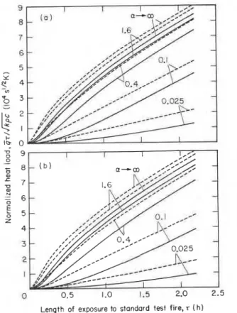
In Fig. 4 the effect of the depth of full-scale furnaces on the normalized heat load on the test specimen is illustrated. The furnace is lined with insulating fire- brick, and its depth is either 2.5 or 0.5 m. Furnaces with a depth of 2.5 m will hereafter be referred to as floor furnaces, those with a depth of 0.5 m as wall furnaces. The test specimen is a normal weight concrete slab. The effect of the heating fuel and combustion conditions enters the problem through the radiation potential of the furnace gas, as reflected by the value of the absorption (emission) coefficient, a. To that coefficient the following
values were assigned in the calculations : 0.025, 0.1, 0.4, 1.6 and 6.4. The lowest of these values probably does not represent any realistic condition, and was added mainly to illustrate a more or less limiting case. Another limiting case is, of course, when a--+m, i.e. the case of black furnace gas. The results for the latter are already available from Fig. 3.
To allow the reader to evaluate the heat absorbed by the furnace boundaries, a piece of information that may be useful in the furnace design, the normalized heat load on the furnace walls is also plotted in this figure as well as in Figs 5 to 7.
It appears from Fig. 4 that for full-scale floor furnaces (i.e. large, deep furnaces) built from good insulating materials, the performance depends only moderately on the nature of fuel and on the combustion conditions, characterized by the absorption coefficient. The perfor- mance of most of them can probably be brought up, with minor improvements, to a level approximating that of the hypothetical furnace heated by black gases. In the
t
The discrepancies would be further reduced by assigning to the product kpc a power slightly higher than 0.5. It is doubtful, how- ever, that such an empirical adjustment, which would greatly distort the dimension of the normalized heat load, is indeed justified on practical grounds.Length of exposure to standard test fire, T ( h )
Figure 4. The effect of furnace depth on the normalized heat load
in standard fire test: full-scale furnace. (a) Furnace depth 0.5 m (wall furnace) ; (b) furnace depth 2.5 m (floor furnace). -, specimen : normal weight concrete; - - - , furnace : insulating firebrick.
case of wall furnaces, on the other hand, the absorptivity of the combustion products may have a sizeable effect on the heat load imposed on the test specimen, in other words, on the efficiency of the furnace. (See the next section for a discussion on furnace efficiency.)
The question is often asked whether there is any way of impriving the heat transfer conditions in a shallow furnace heated by a gas of insufficient radiation potential. It has been suggested that by lining the furnace walls with a material of verv low thermal inertia, the heat load on the test specimen may be substantially increased, and thus the inadequate radiation potential of the heating gas can be compensated for without replacing the burners or changing the fuel. Figure 5 has been prepared to shed some light on this question. It illustrates the effect of the lining material of a full-size wall furnace on the normalized heat load on the test specimen, again assumed to be made from normal weight concrete. It shows that relining a furnace, originally built from fireclay brick (a material of fairly high thermal inertia), with a mineral wool blanket (Fiberfrax) will yield a quite noticeable improvement in the performance of the furnace. Other studies indicated that the im~rovement is less significant in the case of floor (deep) furnaces and for furnaces built from insulating firebrick. There is no doubt, however, that a mineral wool lining always offers great advantages from the point of view of the economy of the furnace operation.
The effect of the nature of specimen material on the furnace performance is illustrated in Fig. 6. Apparently the efficiency of the furnace, as characterized by the
THE FIRE RESISTANCE TEST AND ITS RELATION TO REAL-WORLD FIRES
Length of exposure to standard test fire, r (h)
Figure 5. The effect of furnace lining material on the normalized
heat load in standard fire test: full-scale furnace. (a) Lining: fireclay brick; (b) lining: mineral wool. - , specimen: normal weight concrete;
-
- -, furnace lining: fireclay brick;.
..., furnace lining : mineral wool.I
Length of exposure to standard test fire, r(h)Figure 6. The effect of the nature of specimen on the normalized
heat load in standard fire test: full-scale furnace. (a) Specimen: normal weight concrete: (b) specimen: lightweight concrete. , specimen: normal weight concrete; ---, specimen: lightweight concrete;
- -
- -- -
, furnace : insulating firebricks.Length of exposure to standard test fire, s (h)
Figure 7. The effect of furnace size on the normalized heat load
in standard fire test: full-scale furnace. (a) Full-scale furnace,
3 x 3 x 0.5 m ; (b) small-scale furnace, 1 x I x 0.5 m. -, specimen : normal weight concrete; - -
-
- - -, furnace : insulating firebrick.normalized heat load imposed on the test specimen, improves if the specimen has a lower thermal inertia, especially in the case of furnaces heated with gases of low radiation potential.
Finally, the effect of the furnace size on the test result is illustrated in Fig. 7. It shows that the heat load on a test specimen in a small-scale test is lower than that in a full-scale test. Consequently, selecting a heating techni- que that produces combustion gases of high radiation potential is a very important part of the design of small- scale test furnaces. The problem of flame emissivity can be avoided if the furnace is heated electrically by a near- black-body radiator.20
By reflecting on Figs 3 to 7, two conclusions become apparent. The first is that the results of fire resistance tests can yield reproducible results with well-defined meanings only if a special effort is made at the time of furnace design to ensure that the combustion products of the heating fuel be as nearly black as possible. The absorption-emission characteristics of the gases are especially critical in the case of wall furnaces and small- scale furnaces. There can be hardly any doubt that the fire resistance test furnaces now in use operate at widely different levels of efficiency, and very few of them are capable of yielding a performance that comes sufficiently close to that of a black-gas furnace.
The second conclusion is that, although the theorem of uniformity of normalized heat load is not strictly correct, it is a proposition that works quite satisfactorily with high efficiency (well-designed) fire test furnaces. In fact, in the case of well-designed furnaces, it appears
T. Z. HARMATHY
Length of exposure to standard test fire, T ( h
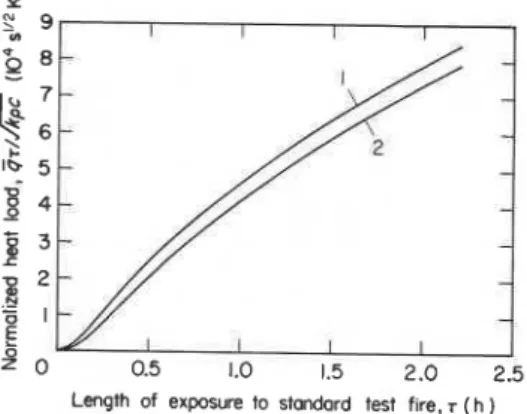
Figure 8. Unified correlations between
Q T / ~ / G
and T forstandard fire tests. Curve 1 , for a black-gas furnace. Curve 2, for the floor test furnace in the author's laboratory (estimated).
permissible to disregard the usually small variations caused by the differences in the thermal inertia of the specimen material (Fig. 3), and to define the normalized heat load versus time of fire exposure relation by a single curve. With the information listed in Table 1 in mind, the selection of the curve representing normal weight concrete specimens in Fig. 3 seems logical, as one which will yield values that will err most of the time on the safe side. Reproduced in Fig. 8, that curve (curve 1) can be regarded as representative of the performance to be striven toward in the design of test furnaces.
Naturally, for most fire test furnaces now in use, the normalized heat load versus time of fire exposure curve is expected to follow a flatter course, the flatness of the curve depending on the degree of deficiency in their operational characteristics. For example, it is estimated on the basis of the measured 'effective' value of the absorption coefficient (about 0.2) that curve 2 of Fig. 8 would be approximately applicable to the floor furnace in the author's laboratory. Clearly, with the use of that furnace a 10-22
%
extension of the time of fire exposure is needed (the lower values relate to longer tests) to match the fire load that a furnace heated by a near- black gas would impose on the test specimen. To enable the reader to put the significance of curve 2 in proper perspective, it is emphasized again that floor furnaces in general, and those lined with mineral wool in particular, can be regarded as being of relatively high efficiency among those used in North America.?MEASURING THE EFFICIENCY OF FIRE TEST FURNACES
The question naturally arises now of how the efficiency level of existing test furnaces can be determined. That question can, of course, be answered by assessing, from measurements similar to those described earlier, the effective value of the absorption (emission) coefficient of the furnace gas. It appears from Fig. 4 that the lowest acceptable value of the effective value of the absorption coefficient is 0.4 for floor furnaces and about 0.9 for wall furnaces, provided that they are lined with good insulating materials.
t
Some oil-heated furnaces in Europe are believed to operate at higher efficiencies.A more convenient and perhaps more accurate
method serving the same end would be to subject a test specimen built from a well-defined material to a standard fire test of an agreed-upon duration, say T = 3600 s.
It has been shown1 that the maximum rise of tempera- ture, (T-TO)m, at some distance, a, from the exposed surface, such that
is a measure of the heat load imposed on the test ,
specimen :
(It must be kept in mind that the maximum temperature rise will occur some time after the termination of the test.)
The efficiency of a particular furnace can be determined by relating the experimentally determined value of (T-TO)m to that derived from a test performed on an identical specimen in a high efficiency (e.g. oil-heated and deep) furnace.?
HEAT LOAD IN REAL-WORLD FIRES
Since in real-world fires the radiation potential of the combustion gases (by virtue of their high luminosities) is, as a rule, much higher than in test fires, and the combustion chamber (compartment) is much larger, a compartment on fire is analogous to a test furnace heated by near-black gas. On the strength of the informa- tion presented earlier, the approximate validity of the theorem of uniformity of normalized heat load can there- fore be taken for granted. Thus, by virtue of Eqn (5),
the use of the normalized over-all heat load as a quantita- tive descriptor of the fire itself-more exactly, as a descriptor of the destructive potential of the fire with respect to the boundary elements of the compartment- is justified.
The normalized overall heat load on the compartment boundaries can be approximated in a crude way from common sense considerations. The upper limit for the chemical energy that can be released in a compartment if fire occurs is obviously GAH, where G is the total 'fire load' (i.e. total mass of combustible items) and AH is the heat of combustion of the combustibles. Hence, the maximum value that the normalized overall heat load can conceivably assume is
1 GAH
d k p c At
where d k p c is to be determined, with the aid of Eqn (I), from the thermal inertias of the boundary elements of the compartment.
Fortunately, in reality a fire is always far more benign than one would judge from the value of ( q ~ / d k T ) m .
t
According to Fig. 3, for a 1 h fire test performed in a hypo- thetical black-gas-heated furnace, the value of 47/2/kFc should be somewhere between 4.65 and 5.40 x lo4 s1I2 K. Relating the experi- mentally determined values of the normalized heat load to these theoretical values is not recommended, however, owing to the uncertainty that exists concerning the 'effective' thermal properties of the material.T. Z. HARMATHY
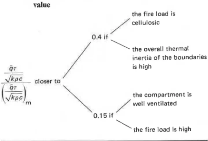
Table 4. The normalized overall heat load on compartment
boundaries as a fraction of its hypothetical maximum
value
,the fire load is cellulosic
\
the overall thermal inertia of the boundariesC 07 is high I I
2!!zic
,lo*, to/
\
,the compartment is well ventilatedI
'the fire load is highThe reason is that not all the chemical energy contained in the combustibles will be absorbed by the compart- ment boundaries. Some of it will be released outside the compartment, but even of the portion released inside, some will leave the compartment with the fire gases as sensible heat, and some will .be lost by radiation through the ventilation openings. Detailed studies indicated2 that the heat absorbed by the compartment boundaries rarely amounts to more than 40% of the chemical energy contained in the combustibles, and may be as low as 15%. A rough guide for the assessment of the applicable percentage is given in Table 4. In general, a fire safety design based on the assumption that
(4~/2/kpc)/(4~/2/kTc)rn E 0.4 can be regarded as a
conservative one. Those who are conscious of the economy aspect are advised to follow the calculation procedure for (g~)/.\/kTc as described in Ref. 2. (It may be noted here that a simple formula, based on an empirical correlation of hundreds of results, will soon be a ~ a i l a b l e . ) ~ ~
In the design of compartment boundaries for fire safety, the value of total fire load, G is to be selected on
stochastic considerations. If G is selected in the manner
described by Lie,22 the design will include the appro- priate degree of safety compatible with the aspects of economy.
Once the value of the normalized overall heat load for a compartment is known, either from estimation or from detailed or simplified calculations, the fire resistance requirement (i.e. the time of exposure to standard fire test to match that value) for all boundary elements of the compartment can be determined from a correlation
q ~ / d G
versus T (time of exposure to test fire) prepared(or estimated) for the particular fire resistance furnace, e.g. from curve 2 of Fig. 8 for the floor furnace in the author's laboratory.
CONCLUSIONS
I
With the decision by ASTM Committee E05 that thetest standard El19 be revised and even completely re-
written if necessary, the interpretation of the results of standard fire resistance tests has come into the focal point of interest. Generations of fire researchers have been plagued by the question of whether the thousands of fire tests conducted so far using the conventional methods did indeed provide the public with meaningful and reproducible information, and if not, how the tests should be conducted in the future to rectify the existing faults. Coupled with that question is, of course, the long-standing problem of how to relate the perfor- mance of building elements in test fires to their perfor- mance in real-world fires.
This paper is an attempt to answer those questions. It has been shown that the method in which fire test furnaces are heated has a marked influence on their efficiencies, especially if they are shallow or smaller than standard size. If all test furnaces had been designed for highly efficient operation, the heat load they impose on the test specimen could .be determined from a unique plot correlating the normalized value of the heat load
with the duration of fire test (curve 1 of Fig. 8).
The performance of not-so-efficient furnaces depends not only on the characteristics of the test furnace but also on the characteristics of the test specimen. Relining a furnace with a material of very low thermal inertia, although helpful, is not likely to bring the performance of the furnace up to the required level. Methods of determining the efficiency of existing test furnaces have been outlined.
Further investigations have revealed that the theorem of uniformity of normalized heat load is approximately valid under real-world fire conditions. The highest conceivable value for the normalized overall heat load on the compartment boundaries, in other words the highest possible destructive potential of a fire that may occur in the compartment, can be estimated from infor- mation on the fire load which, if arrived at on stochastic considerations, includes a certain margin of safety. In real-world fires the actual normalized overall heat load amounts to only 1 5 4 0 % of the limiting highest value.
Once the normalized overall heat load for a compart- ment is known, the fire resistance requirement for the boundaries of the compartment can be determined from plots of normalized heat load versus time of fire exposure (e.g. curve 2 of Fig. 8) which, in general, are expected to be somewhat different for test furnaces of different designs. Uniformity in the exposure requirements and in the interpretation of the test results cannot be achieved without ensuring that all test furnaces operate at an efficiency close to that of a black-gas furnace.
Acknowledgements
The author is indebted to Professor S. Hadvig of the Technical University of Denmark for computing the mean beam lengths for radiation that are presented in Table 3. The author also wishes to thank Dr J. R. Mehaffey for his help in the computer programming, and Messrs J. W. MacLaurin, G. P. Crampton and B. C. Taber for performing the absorption-emission tests on the NRCC floor test furnace gases. This paper is a contribution from the Division of Building Research, National Research Council of Canada, and is published with the approval of the Director of the Division.
T. Z. HARMATHY REFERENCES
1. T. Z. Harrnathy, Fire Mater. 4, 71 (1980).
2. T. 2. Harmathy, Fire severity: basis for fire safety design.
Paper presented at the International Symposium on Fire Safety of Concrete Structures, Fall Convention of the American Concrete Institute, San Juan, Puerto Rico (September 1980).
3. T. Z. Harmathy, Fire Technol. 5, 140 (1 969).
4. L. G. Seigel, in Fire Test Performance, p. 57. Spec. Tech.
Publ. 464. American Society for Testing and Materials, Philadelphia, (1 970).
5. J. van Keulen, Comparison of heat transfer in several wall furnaces. Report No. BVI-74-17. TNO, Delft (1974). 6. A. M. Kanury and D. J. Holve, A theoretical analysis of the
ASTM E-119 standard fire test of building construction and materials. Report No. NBS-GCR 76-50. National Bureau of Standards, Washington, DC (1 975).
7. J. B. Fang and J. T. Scott, Heat transfer in furnaces for CIB cooperative program and heat balance analysis of wall furnace. Report No. NBSlR 75-794. National Bureau of Standards, Washington, DC (1 975).
8. 0. R. Paulsen and S. Hadvig, J. Fire Flammability 8, 423
(1 977).
9. E. R. G. Eckert and R. M. Drake, Heat and Mass Transfer,
p. 407. McGraw-Hill, New York (1959).
10. T. 2. Harmathy and J. A. C. ~lanchard; Can. J. Chem. Eng.
41, 128 (1963).
11. Time constant measurements and calculations on furnace thermocouple assemblies. Research Report RR E5 1001. American Society for Testing and Materials, Philadelphia
f , 1977). -~ ,-
12. G. Forsythe and C. B. Moler, Computer Solution of Linear
Algebraic Systems, p. 132. Prentice-Hall, Englewood Cliffs, New Jersey (1 967).
13. T. Z. Harmathy, in Fire Test Performance, p. 209. Spec.
Tech. Publ. 464. American Society for Testing and Materials, Philadelphia (1 970).
14. T. T. Lie and T. Z. Harmathy, A numerical procedure t o calculate the temperature of protected steel columns exposed to fire. Fire Study No. 28, NRCC 12535. National Research Council of Canada, Division of Building Research, Ottawa (1 972).
15. H. S. Carslaw and J. C. Jaeger, Conduction of Heat in Solids,
,
2nd Edn, p. 76. Oxford University Press (1959).
16. W. H. McAdams, Heat Transmission, 2nd Edn, pp. 74, 395.
McGraw-Hill, New York (1942).
17. R. A. Sherman, Trans. ASME 56, 177 (1 934).
18. W. Trinks, Industrial Furnaces, 4th Edn, Vol. I, p. 32. Wiley
London (1 951 ).
19. P. A. Croce, A study of room fire development: the second full-scale bedroom fire test of the home fire project (July
24, 1974). Volume II, Analysis of Test Results. FMRC Ser.
No. 2101 1.4. Factory Mutual Research, Norwood, Masa- chusetts (1 975).
20. J. A. C. Blanchard and T. Z. Harmathy, Small-scale fire test
facilities of the National Research Council. Fire Study No. 14, NRC 8207. National Research Council of Canada, Division of Building Research, Ottawa (1 964).
21. J. R. Mehaffey and T. Z. Harmathy, Assessment of fire
resistance requirements.
22. T. T. Lie, Can. J. Civ. Eng. 6, 617 (1 979).
Received 6 April 1981
Heyden & Son Ltd, 1981
NOMENCLATURE
a distance of a selected point from the surface (m) T temperature (K)
A area (m2) x distance from the surface (m)
b principal dimensions of the furnace chamber Ax distance between mesh points (m) and test specimen (m)
B radiative heat flux leaving the surface (W m-2) a absorption (emission) coefficient (m-l) c specific heat (J kg-1 K-1) Y transmissivity, dimensionless
d depth of furnace chamber (m) E emissivity of solid surface or, with subscript g,
f
polynomial of furnace gas, dimensionlessF configuration factor, dimensionless P density (kg m-3)
G total fire load (kg) u Stefan-Boltzmann constant (5.67 x 10⁻⁸ Wm-2
h heat transfer coefficient (W m-2 K-1) K-4)
AH heat of combustion (J kg-1) T duration of (standard or real-world) fire (s)
i = 1, 2, 3,
. .
.,
n- 1, n, denoting either furnace(or compartment) boundary elements or mesh Subscripts points in the boundary-forming materials av average
I coefficient g of furnace gas
j = 0 , 1 , 2 , 3
, . . .
i of the ith element of furnace (or compartment)J coefficient boundary; at the ith mesh point
k thermal conductivity (W m-1K-1) m maximum
K coefficient t total (for the furnace or the compartment)
I slab thickness (m) 1, 2,
. . .
, i,.
. .
, n for the lst, 2nd,. .
.
, ith,. . .
, nth L mean beam length (m) surface or surface-forming materialm = 1 , 2 , 3 , . . . , j 0, 1,
. .
.,
i-1, i, i + l ,. .
.,
n at x=O, Ax, (i-l)Ax, iAx, n number of furnace (or compartment) boundary (i+ l)Ax,.
. .
, nAx, respectivelyelements; number of mesh points, dimension- v, v + 1 for the vth, (v+ 1)th approximation less
4 rate of heat absorption (W m-2) Superscripts
4
temporal average of heat absorption (W m-2) 0, 1, 2,. .
.,
,j-m,.
. .
j- 1, j, j+ 1,. . .
at t=O, At, 2At, t time (s). .
.,
(,j-m)At,. .
.,
(j- l)At, jAt, ( j + l)At,At time increment (s) respectively
This publication is being distributed by the Division of Building R e s e a r c h of the National R e s e a r c h Council of Canada. I t shouldnot be reproduced in whole o r in p a r t without p e r m i s s i o n of the original publisher. The Di- vision would b e glad to b e of a s s i s t a n c e i n obtaining s u c h p e r m i s s i o n .
Publications of the Division m a y b e obtained by m a i l - ing the a p p r o p r i a t e r e m i t t a n c e (a Bank, E x p r e s s , o r P o s t Office Money O r d e r , o r a cheque, m a d e payable
to the R e c e i v e r G e n e r a l of Canada, c r e d i t NRC) t o t h e National R e s e a r c h Council of Canada, Ottawa. K1A OR6. Stamps a r e not acceptable.
A l i s t of a l l publications of the Division i s available and m a y b e obtained f r o m the Publications Section, Division of Building R e s e a r c h , National R e s e a r c h Council of Canada, Ottawa. KIA OR 6.