30 nm In[subscript 0.7]Ga[subscript 0.3]As inverted-type
HEMTs with reduced gate leakage current for logic applications
The MIT Faculty has made this article openly available.
Please share
how this access benefits you. Your story matters.
Citation
Tae-Woo Kim, Dae-Hyun Kim, and J.A. del Alamo. “30 nm
In0.7Ga0.3As Inverted-Type HEMTs with reduced gate leakage
current for logic applications.” Electron Devices Meeting (IEDM),
2009 IEEE International. 2009. 1-4. ©2010 Institute of Electrical and
Electronics Engineers.
As Published
http://dx.doi.org/10.1109/IEDM.2009.5424317
Publisher
Institute of Electrical and Electronics Engineers
Version
Final published version
Citable link
http://hdl.handle.net/1721.1/59453
Terms of Use
Article is made available in accordance with the publisher's
policy and may be subject to US copyright law. Please refer to the
publisher's site for terms of use.
30 nm In
0.7Ga
0.3As Inverted-Type HEMTs with Reduced Gate
Leakage Current for Logic Applications
Tae-Woo Kim, Dae-Hyun Kim and Jesús A. del Alamo
Massachusetts Institute of Technology (MIT), Cambridge, MA 02139, U.S.A, E-mail: twkim78@mit.edu
Abstract
We have fabricated 30 nm In0.7Ga0.3As Inverted-Type
HEMTs with outstanding logic performance, scalability and high frequency characteristics. The motivation for this work is the demonstration of reduced gate leakage current in the Inverted HEMT structure. The fabricated devices show excellent Lg scalability down to 30 nm. Lg = 30 nm devices
have been fabricated with exhibit gm = 1.27 mS/μm, S = 83
mV/dec, DIBL = 118 mV/V, ION/IOFF = 4 x 10⁴, all at 0.5 V.
More significantly, the removal of dopants from the barrier suppresses forward gate leakage current by over 100X when compared with equivalent normal HEMTs. The Lg = 30 nm
devices also feature record high-frequency characteristics for an inverted-type HEMT design with fT = 500 GHz and fmax =
550 GHz.
Introduction
As conventional Si CMOS scaling approaches the end of the roadmap, III-V based FETs appear as an increasingly viable alternative to continue transistor size scaling [1-2]. A great deal of the excitement about the prospects of III-Vs comes from the excellent logic characteristics that have recently been demonstrated in InGaAs HEMTs with gate lengths as small as 30 nm [3]. While being quite far in structure from an ideal logic III-V MOSFET, the HEMT has demonstrated to be an excellent model system to study fundamental device physics and technology issues and to provide well calibrated and relatively parasitic-free device results to support the development of simulators that would allows us to chart the future of a III-V logic technology [4].
In this regard, there is great value in continuing to push the scaling of HEMTs so as to explore significant device physics issues in the relevant dimensional range. It is well known that lateral scaling demands harmonious vertical scaling. Reduction of insulator thickness results in greatly increased gate leakage current [5]. This is what currently limits the reduction in HEMT lateral dimensions. Suppressing this, would allow us to scale the HEMT below 30 nm while preserving excellent logic characteristics. In this work, we demonstrated an inverted-type HEMT design that mitigates forward gate leakage current by over two orders of magnitude and yields excellent logic characteristics. This device architecture is also directly amenable to the incorporation of a high-K gate dielectric in the gate stack which should allow much further scaling.
Process Technology
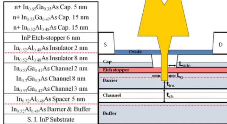
Fig. 1 shows a cross section of epitaxial layer structure used
in this work and a schematic of the fabricated device structure.
Our device features an InAlAs/InGaAs double-heterostructure design where the upper Si-doping is located further away from the channel than in conventional designs (8 nm vs. about 3 nm). As a result, after a triple recess process [5], the dopant layer is eliminated in the intrinsic device resulting in a dopant-free InAlAs barrier. This gives rise to a conduction band shape for the barrier that, for the same sheet carrier concentration, is more rectangular than in the conventional design, as shown in
Fig. 2. This should significantly suppress gate leakage current,
especially in the forward gate bias regime.
Device fabrication follows closely our previous device demonstrations [6]. We use a three-step recess process that yields a barrier thickness in the intrinsic region, tins, of about 4
nm. In this work, we have devices with Lg values in the range
of 30 to 130 nm. Fig. 3 shows STEM images of a fabricated 30 nm device. The side-recess-length (Lside) was set at 80 nm.
Fig. 1 Heterostructure and schematic of InGaAs Inverted
HEMT. It features delta-doping in the top InAlAs layer that is etched away in the intrinsic device
DC and Logic Characteristics
Fig. 4 shows output characteristics of an inverted HEMT
with Lg of 30 nm. The device exhibits excellent pinch-off and
saturation characteristics. Fig. 5 shows the subtreshold and gate current characteristics of a 30 nm I-HEMT against those of a previously demonstrated normal In0.7Ga0.3As HEMT with
a similar channel design, barrier thickness (4 nm), gate length, and Lside value. The inverted HEMT displays comparable
subthreshold characteristics to the normal HEMT with a subthreshold swing of 83 mV/dec and DIBL of 118 mV/V at VDS = 0.5 V. Remarkably, the inverted HEMT exhibits much
lower values of OFF-state current and gate leakage current, especially in the forward regime where a reduction of over 100X is achieved.
0 10 20 30 40 -0.3 -0.2 -0.1 0.0 0.1 0.2 0.3 0.4 El ect ron densi ty [ x 10 18 /c m 3 ] CB Prof ile s [ e V] Vertical depth [nm] Inverted HEMT Normal HEMT VGS=+0.22V for I-HEMT VGS=+0.25V for N-HEMT 0.0 0.5 1.0 1.5 2.0
Fig. 6 shows subthreshold characteristics for devices with Lg
from 130 nm down to 30 nm at VDS = 0.5 V, together with gate
leakage current (IG). The devices show harmonious scaling
with very small VT roll off in this dimensional range.
Fig. 2 Self-consistent Schrodinger-Poisson calculation of
conduction band profile and electron density in Inverted HEMT and conventional HEMT at the same ns = 1.3 x
1012/cm3.
Fig. 3 Cross-section STEM images of inverted HEMT with LG
= 30 nm. The barrier thickness, tins is estimated to be 4 nm.
[TEM analysis was carried out at NCNT and UNIST in Korea.]
Fig. 4 Output characteristics of 30 nm InGaAs Inverted HEMT.
Fig. 5 Subthreshold and IG characteristics of 30 nm InGaAs
Inverted HEMT and normal HEMT. Off-state ID and IG
characteristics are greatly suppressed in Inverted HEMT because of the rectangular shape of the barrier.
Fig. 7 shows ION, IOFF and corresponding ION/IOFF ratio as a
function of Lg for both types of devices at VDS = 0.5 V [7].
The inverted HEMT shows much lower values of IOFF, and a
significantly higher ION/IOFF ratio across the entire
dimensional rage when compared with the rectangular HEMT. At Lg=30 nm, the ION/IOFF ratio is ~ 4 x 10⁴. A trade-off of the
inverted design is also evident in this figure. ION for the
inverted HEMTs is slightly lower than for normal HEMTs. This comes from an increase in source resistance (Rs) which
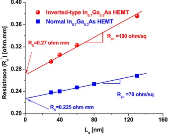
is a consequence of a reduction of the sheet carrier concentration in the extrinsic portion of the device as a result of having the upper Si-doping plane further away from the channel. This can be more quantitatively observed in Fig. 8 which graphs the resistance measured though the gate-current
0.0 0.2 0.4 0.6 0.8 1.0 0.0 0.2 0.4 0.6 0.8 VGS=-0.2V VGS=-0.1V VGS=0V VGS=0.1V VGS=0.2V VGS=0.3V I D [m A/ μ m] VDS [V] -0.50 -0.25 0.00 0.25 10-10 10-9 10-8 10-7 10-6 10-5 10-4 10-3 VDS = 50mV VDS = 0.5 V VDS = 50mV VDS = 0.5 V VDS = 50mV I D & I G [A / μ m] V GS [V] Inverted-type In 0.7Ga0.3As HEMTs Normal In0.7Ga0.3As HEMTs Lg = 30 nm VDS = 0.5 V ID I G IG tins= 4 nm tch= 13 nm Lside= 80 nm IEDM09-484 20.1.2
injection technique, Rs*, as a function of gate length [8]. The
source resistance Rs can be extracted by linear extrapolation
to zero Lg. The extracted Rs of I-HEMT is 0.27 Ω.mm, in
contrast with 0.22 Ω.mm for the normal HEMT. Further improvement in ION can be obtained through optimization of
the epitaxial design to achieve lower Rs.
Fig. 6 Subthreshold and IG characteristics for various values
I-HEMTs with different values of Lg at VDS = 0.5 V. There is a
slight negative shift of VT as Lg scales down to 30 nm.
Fig. 7 ION, IOFF and ION/IOFF ratio vs. Lg for both InGaAs
HEMTs. The Inverted HEMT shows significantly improved ION/IOFF ratio at all gate lengths.
Fig. 8 Measured Rs* as a function of Lg through the gate
current injection technique. Inverted HEMT shows a higher source resistance and sheet resistance of the channel under the gate.
Microwave and Logic Performance
Microwave performance was characterized from 0.5 to 40 GHz. On-wafer open and short patterns were used to subtract pad capacitances and inductances from the measured device S-parameters. Fig. 9 plots the fT and fmax as a function of VGS
at VDS = 0.8 V for Lg=30 nm Inverted and normal HEMTs.
Excellent values of fT = 500 GHz and fmax = 550 GHz have
been obtained for the I-HEMT. These are the highest values of fT and fmax ever reported in an Inverted HEMT. fT is lower
than in the normal HEMT but fmax is significantly higher.
This is due to improved output conductance (go)
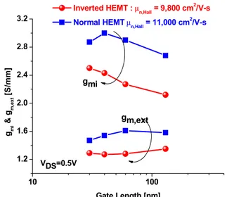
characteristics. In order to understand the somehow reduced fT of the inverted HEMT, Fig. 10 shows extrinsic (gm,ext) and
intrinsic peak transconductance (gmi) which is extracted from
S-parameters after removal of source and drain resistance. gmi
for the Inverted HEMT is lower than that of normal HEMT. This comes from somehow poorer transport in the channel which also manifests itself through a lower electron mobility in the epitaxial structure (μe ~ 9,800 vs. 11,000 cm2/V.s in the
normal HEMT). This is a known drawback of the inverted HEMT design with arises from increased interface roughness of the reverse InGaAs/InAlAs interface [9]. Improved epitaxial growth techniques should mitigate this problem.
To identify the significance of the results obtained in this work, we have benchmarked the logic performance of our devices against advanced Si CMOS technologies. Fig. 11 summarizes the subthreshold swing against Lg for our
inverted HEMT together with normal HEMTs, as well as advanced Si CMOS. Excellent electrostatic integrity is evident. A similar result is obtained for DIBL. We have also performed a rigorous comparison of the logic performance of our inverted and normal HEMTs with Lg = 30 nm and
state-of-the-art 65 nm Si CMOS which has a similar gate length [3, 5]. Fig. 12 plots ION against Ileak characteristics at 0.5 V. Ileak
-0.6 -0.4 -0.2 0.0 0.2 0.4 1E-10 1E-9 1E-8 1E-7 1E-6 1E-5 1E-4 1E-3 I G [A/ μ m] 30nm 40nm 60nm 130nm VDS=0.5V ID [A / μ m] VGS [V] VDS=0.5V 1E-10 1E-9 1E-8 1E-7 1E-6 1E-5 1E-4 1E-3 20 40 60 80 100 120 140 10-10 10-9 10-8 10-7 10-6 10-5 10-4 10-3 10-2 I ON /I OFF ION & I OFF [A / μ m] Lg [nm]
Inverted-type InGaAs HEMTs Normal InGaAs HEMTs
ION IOFF 102 103 104 105 106 107 VDS = 0.5 V 0 40 80 120 160 0.20 0.24 0.28 0.32 0.36 0.40 R sh =70 ohm/sq RS=0.225 ohm mm Inverted-type In0.7Ga0.3As HEMT Normal In0.7Ga0.3As HEMT Resist n ace ( Rs * ) [oh m. mm] Lg [nm] RS=0.27 ohm mm R sh =100 ohm/sq
takes into account the forward gate leakage current and it is a more appropriate figure of merit for devices that suffer from significant gate leakage [5]. We find that at an Ileak of 100
nA/μm, 30 nm Inverted HEMT exhibit 29% higher current drive (ION) than 65 nm High Performance (HP) CMOS
technology with Lg = 35 nm and 20 % higher current drive
(ION) than normal HEMT with Lg = 30 nm.
Conclusions
We have demonstrated 30 nm In0.7Ga0.3As Inverted
HEMTs with outstanding logic performance, scalability and high frequency characteristics. In particular, 30 nm devices exhibit gm,max = 1.27 mS/μm, S = 83 mV/dec, DIBL = 118
mV/V, ION/IOFF = 4 × 10⁴, at VDS = 0.5 V, and fT = 500 and
fmax = 550 GHz at VDS = 0.8 V. The removal of dopants from
the barrier suppresses forward gate leakage current by over 100X. This works suggest that III-V designs similar to an inverted HEMT but with a high-K dielectric as gate insulator have potential for scaling to very small dimensions.
References
[1] S. Datta et al., IEDM, p. 763, 2005. [2] K. M. Lau et al., IEDM, p. 723, 2008. [3] D.-H. Kim et al.., IPRM, p. 132 , 2009. [4] N. Neophytou et al., IEEE TED, p. 1377, 2009. [5] D.-H. Kim et al., IEEE TED, p. 2546 , 2008. [6] D.-H. Kim et al., IEEE EDL, p. 830 , 2008. [7] D.-H. Kim et al., IEEE TED, p. 2606, 2007. [8] D. R. Greenberg et al., IEEE TED, p. 1304, 1996. [9] N. Pan et al., Applied Physics Letters, p. 71, 1991.
Acknowledgements
This work was sponsored by Intel Corporation and FCRP-MSD at MIT. Epitaxial heterostructures were supplied by MBE Technology. Device fabrication took place at the facilities of the Microsystems Technology Laboratories (MTL), the Scanning Electron Beam Lithography (SEBL) and the Nano-Structures Laboratory (NSL) at MIT.
Fig. 9 Bias dependence of fT and fmax for Lg = 30 nm devices
at VDS = 0.8 V.
Fig. 10 Intrinsic transconductance (gmi) and extrinsic
transconductance (gm,ext) as a function of gate length.
Fig. 11 Subthreshold swing of Inverted and Normal InGaAs
HEMTs as a function of Lg, together with those of advanced Si
nFETs.
Fig. 12 ION against Ileak for 30 nm InGaAs HEMTs, and both
low-power and high-performance 65 nm CMOS, all at VDD =
0.5 V. 10 100 1.2 1.6 2.0 2.4 2.8 3.2 gm,ext gmi & g m, ex t [ S /mm] Gate Length [nm] Inverted HEMT : μn,Hall = 9,800 cm
2
/V-s Normal HEMT μn,Hall = 11,000 cm
2 /V-s VDS=0.5V gmi -0.3 -0.2 -0.1 0.0 0.1 0.2 0 .3 0.4 0 .5 0 100 200 300 400 500 600 700 f m ax fT fm a x Inverted H E M T N orm a l H E M T fT & f ma x [G Hz ] VG S [V ] f T VD S=0.8V Lg = 30 nm 0.010-9 10-8 10-7 10-6 0.1 0.2 0.3 0.4 0.5
InGaAs Inverted-type HEMT Lg = 30 nm
65 nm CMOS Intel Low Power Lg = 55 nm
InGaAs normal HEMTs Lg = 30 nm ION [A / μ m] Ileak [A/μm] VDD = 0.5 V 65 nm CMOS
Intel High Performance Lg = 35 nm x 10-3 10 100 60 80 100 120 140 160 180 Gate Length [nm] Su bt h res h o ld Sl o p e [ m V /de c] Inverted HEMT Normal HEMT Si FETs (IEDM) IEDM09-486 20.1.4