HAL Id: hal-01853129
https://hal.archives-ouvertes.fr/hal-01853129
Submitted on 2 Aug 2018HAL is a multi-disciplinary open access archive for the deposit and dissemination of sci-entific research documents, whether they are pub-lished or not. The documents may come from teaching and research institutions in France or abroad, or from public or private research centers.
L’archive ouverte pluridisciplinaire HAL, est destinée au dépôt et à la diffusion de documents scientifiques de niveau recherche, publiés ou non, émanant des établissements d’enseignement et de recherche français ou étrangers, des laboratoires publics ou privés.
Design of Optimum Torsionally Flexible PropRotors for
Tilt-Body MAVs
Fazila Mohd Zawawi, Joseph Morlier, Gilles Grondin, Jean-Marc Moschetta
To cite this version:
Fazila Mohd Zawawi, Joseph Morlier, Gilles Grondin, Jean-Marc Moschetta. Design of Optimum Torsionally Flexible PropRotors for Tilt-Body MAVs. Applied Mechanics and Materials, Trans Tech Publications, 2012, AEROTECH IV, 225, pp.281-286. �10.4028/www.scientific.net/AMM.225.281�. �hal-01853129�
This is an author-deposited version published in: http://oatao.univ-toulouse.fr/
Eprints ID: 6520
To link to this article: DOI:10.4028/www.scientific.net/AMM.225.281
URL: http://www.scientific.net/AMM.225.281
To cite this version: Mohd Zawawi, Fazila and Morlier, Joseph and Grondin, Gilles and Moschetta, Jean-Marc Design of Optimum Torsionally Flexible
PropRotors for Tilt-Body MAVs. (2012) Applied Mechanics and Materials -
AEROTECH IV - Recent Advances in Aerospace Technologies, vol. 225. pp. 281-286. ISSN 1660-9336
O
pen
A
rchive
T
oulouse
A
rchive
O
uverte (
OATAO
)
OATAO is an open access repository that collects the work of Toulouse researchers and makes it freely available over the web where possible.
Any correspondence concerning this service should be sent to the repository
Design of Optimum Torsionally Flexible
PropRotors for Tilt-Body MAVs
F. Zawawi
1,a, J. Morlier
2,b,
G. Grondin
3,cand JM. Moschetta
4,d1,2,3,4
Institut Supérieur de l’Aéronautique et de l’Espace (ISAE), 31055 Toulouse, France
2
Institut Clement Ader (ICA), 31055 Toulouse, France
1
Universiti Teknologi Malaysia (UTM), 81310 Skudai, Malaysia
a
[email protected], [email protected], [email protected],
d
Keywords: tilt-body aircraft, micro-air vehicles, strip theory, minimum energy loss, low Reynolds number, optimum propeller/rotor blades, passively adaptive blades, long flight endurance
Abstract. This paper presents a methodology to design the optimum proprotor for tilt-body
micro-air-vehicles (TB-MAV) with efficient global propulsion system and long flight endurance in both cruise and hover modes. The TB-MAV developed at ISAE, which is called MAVion, was used as a baseline in the design process. To acquire maximum performance of TB-MAV’s global propulsion system, an efficient optimization process of the proprotor propulsion system was carried out. The optimization process consists of two-step inverse design methods. The first step determines the optimal operating conditions in terms of power and rotational speed of proprotor and the second step designs the optimal blade geometry in terms of twist angle distribution. The optimal blade twist distribution along the blade was computed using the Glauert’s strip theory for minimum energy loss condition. Meanwhile, the optimal operating conditions were determined by the motor outputs corresponding to high motor efficiency. A comparison of performance in terms of total efficiency and flight endurance between the optimized flexible proprotor, the optimized rigid proprotor, optimized propeller and optimized rotor is presented.
Introduction
Tilt-body micro-air-vehicles (TB-MAV) have been regarded over the last decade as promising candidates for convertible multi-tasking configuration as they intrinsically combine both vertical and horizontal flight capabilities. Such convertible MAVs can provide better observation abilities during hovering while offering faster forward movement during cruising. However, in these two flight modes the rotor operates under considerably different conditions where using a conventional rotor will require high power consumption or even inability to provide sufficient required thrust in the off-design cases. The substantial variations of blade pitch and twist that are required to offer highest possible efficiency at both flight modes require an active
control system to change the shape according to the flight configurations. Nonetheless, the active blade shape modification concept is inapplicable for small-sized rotor (blade ~3mm of thickness) due to its complexity and the unavailability of control devices in the small size range, and requires non-mechanical control system to be used. Structural topology optimization where the mass density distributions along the blade is optimized according to the desired aerodynamic loadings [1] and off-axis carbon fiber composites for blade twisting moment introduction, are among the potential concepts to structurally design the passively adaptive blades. Thus, the idea behind the passive blade shape modification concept is to compute the optimal twist distribution for TB-MAV hingeless proprotor for both cruise and
hover mode. The difference of optimized blade twist between these two flight modes and its corresponding resulting aerodynamic loadings to enable twist deformation, can be used as design inputs to structurally design the flexible blade by using inverse methods of blade structural stiffness distribution identification [2].
Fig.1 MAVion (Dimensions: 400mmx220mm) in hover
Blade Twist Optimization
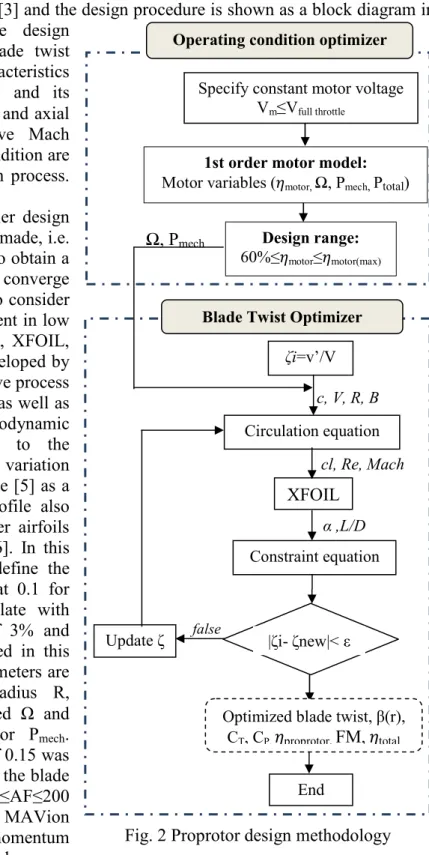
A numerical iterative method for computing the optimal blade twist angle distribution along the blade span in horizontal and vertical flight, with identical chord laws, was developed adapting the inverse design method of proprotor using Blade Element Momentum Theory (BEMT) based on Minimum Induce Loss (MIL) that satisfies the Betz’s condition. The systems of equations used were proposed by Adkins and Liebeck [3] and the design procedure is shown as a block diagram in Fig. 2 (lower part). This iterative design
procedure determines the optimal blade twist angle along the radius (β(r)), the characteristics
of the designed proprotor (CT, CP) and its
performance ( proprotor, FM). The radial and axial
interference factors, Re, and relative Mach number depending on the operating condition are also iteratively computed in the design process. The details are described in [3].
In the classical approach of propeller design and analysis, different assumptions are made, i.e. lift polar is a linear function, in order to obtain a closed loop solution or even to quickly converge the iterative process. Hence, in order to consider non-linear airfoil characteristics prevalent in low Reynolds number regime (Re<70,000), XFOIL, an airfoil design and analysis code developed by Drela [4] was integrated into the iterative process of design to eliminate this assumption as well as
to precisely compute the aerodynamic
coefficients. The airfoil sensitivity to the turbulence level and Reynolds number variation was eliminated by using cambered plate [5] as a blade profile. The cambered plate profile also promises better performance than other airfoils in MAVs Reynolds number regime [6]. In this
respect, the ncrit parameter, used to define the
turbulence level in XFOIL, was set at 0.1 for both flight modes. The cambered plate with thickness t/c of 2.5%, camber f/c of 3% and camber location xf/c of 30% was used in this study. For optimization, the input parameters are number of blades B, proprotor radius R, operational speed V, rotational speed Ω and
mechanical power into the proprotor Pmech.
Constant non-dimensional chord c/R of 0.15 was used to ensure the activity factor AF of the blade is in the range of practical propeller, 90≤AF≤200 [7]. The proprotor diameter D used for MAVion was set at 18cm to ensure the momentum injected into the flow by the propwash covers
almost the entire span of the MAVion’s body. This will avoid the flow separation on the MAV’s body while performing a transition between the two flight modes. To evaluate the performance of
proprotor, the computed quantities are the proprotor in forward flight and the figure of merit FM in
hover as defined in Eq. 1.
1st order motor model: Motor variables ( motor, Ω, Pmech, Ptotal)
Fig. 2 Proprotor design methodology End
Optimized blade twist, β(r), CT, CP, proprotor, FM, total Ω, Pmech c, V, R, B ζi=v’/V false Update ζ α ,L/D cl, Re, Mach XFOIL Constraint equation Circulation equation |ζi- ζnew|< ε
Specify constant motor voltage Vm≤Vfull throttle
Design range: 60%≤ motor≤ motor(max)
Blade Twist Optimizer Operating condition optimizer
η proprotor= J. CT CP, FM= CT3/2 √2.CP (1)
where J is the advance ratio, CT is the thrust coefficient and CP is the power coefficient, which are
respectively defined in Eq. 2 as:
J=60. V Ω.D, CT= T ρ. Ω 60 2 .D4 , CP= Pmech ρ. Ω 60 3 .D5 (2)
By knowing the performance of proprotor, the total in cruise and hover can be respectively
computed by using relationships in Eq. 3. η
total(cruise)=ηmotor.ηproprotor, ηtotal(hover)=ηmotor.FM (3)
Operating Condition Optimization
In order to control the global propulsion system to be in high performance in both flight modes,
the design range of operating conditionswas first specified. The operating conditions in the design
process of optimal blade twist are the motor outputs in terms of Pmech and Ω corresponding to the
specified motor. The motor voltage Vm must be carefully chosen to satisfy the design requirements.
In this study, the initial Vm was set up based on the performance data of MAVion which is the
motor outputs at 10V with 60%≤ motor≤ motor(max) were set, as can be seen in Fig. 4. However, the
designed proprotor blade at given operating conditions from the motor outputs is subject to the design requirements. Since two proprotors were used in the MAVion in order to control the yaw
direction, the Treq at cruise flight was constrained by the half of MAVion’s drag at the target
cruising velocity V=16m/s. Whereas for the hover flight, Treq was constrained by the half of the
MAVion’s weight of 350 grams. The design requirement for MAVion proprotor at each flight configuration is shown in Table 1.
Table 1 Design requirements for proprotor
Flight configuration Velocity, V (m/s) Required thrust, Treq (N)
Hover 0 1.7
Cruise 16 0.31
The design constraint considered in this study is the twist deformation between cruise and hover,
∆β= |∆β(cruise)-∆β(hover)|. The value needs to be as small as possible in order to be able to manufacture
the passive control blade, also the desired twist deformation to be possibly adjusted by the aerodynamic loadings. For the design of this study, the ∆β was set as ≤8°. According to the theory of propeller design based on MIL, by increasing the proprotor Ω in the cruise can decrease the optimal blade twist angle. In contrast in the hover flight mode, the optimal blade twist increases as the Ω decreases. This will be advantageous in the design of optimal blades for proprotor where the ∆β can be minimized. From the first order motor model law, higher the voltage can provide
maximum motor at higher Ω as illustrated in Fig. 3. Hence, by freezing the motor outputs at around
maximum motor can promise long flight endurance due to low Ptotal[8]. A direct current motor of
AXI2204/54EVP with motor speed constant =1400 rev/min/Volt, zero load current I =0.35A
and internal resistance Rm=0.32 ohm, was used in this study. The motor output variables at constant
Vm were computed using relationships in Eq. 4 [8] and are plotted in Fig. 3 and Fig. 4.
Ptotal= Vm- ΩKv Rm .v, Pmech= Vm- Ω Rm , ηmotor= Ptotal Pmech (4)
Fig. 3 AXi2808/04 motor efficiency at
different voltages Fig. 4 Motor output variables vs motor
speed at 10V of applied voltage
From the known Ptotal supplied into proprotor, the endurance of the flight is computed by the
relationship in Eq. 5.
Endurance time, tend= E
Ptotal=
C.K.Vb
Ptotal (5)
where E is the battery energy stored, C is the battery capacity, K is the number of battery cells and
Vb is the nominal battery voltage. For MAVion, three cells of Polymer Lithium Ion battery
(Vb=3.7Volts/cell, C=1000mAh) were used in MAVion for its small size and light weight as well as
high energy density for long endurance flight.
Results and Analysis
The developed iterative process of proprotor analysis using BEMT method was first validated with the results given by QPROP and corresponding experiment measurement. A 2-bladed rotor with a rectangular planform (R=0.1m, c=0.02m), flat plate blade profile with a thickness t/c=2.5% and blade pitch of 25° was used in the validation process. From the validation result in Fig. 5, it is found that the BEMT method with the integration of XFOIL shows good agreement with the experimental measurement. QPROP, a propeller analysis tool with simplified and limited lift polar, showed unacceptable correlations due to its incapability to predict aerodynamic coefficients at post-stall region. The design of propulsion system in
hover and cruise was done separately. The optimal blade twist within the specified design range of operating conditions was obtained. The results for hover case are shown by Fig. 6 and Fig. 7, and the results for cruise case are shown
by Fig. 8 and Fig. 9. To generate the Treq in a
hover, the rotational speed of Ω=12,870 and the designed blade corresponding to this Ω is shown
by a dashed line in Fig. 6. Whereas to attain Treq
in cruise at Vc=16m/s, the proprotor needs to
operate at Ω=13,500 can be observed in Fig. 9.
The design at Vc>16m/s was done to find the
maximum Vc that passive control blade can
achieve. And it is found that the MAVion is not able to cruise beyond 16m/s using passively flexed proprotor. 0 20 40 60 80 100 0 3 6 9 12 15 η _ m ot or ( % ) Rotational speed, Ω (x103) Vm=4V Vm=6V Vm=8V Vm=10V 0 100 200 300 400 0 20 40 60 80 100 0 3 6 9 12 15 P ow er , P ( W ) E ff ic ie nc y , (% ) Rotational speed, Ω (x103) _motor P_total P_mech Design range m>60%
Fig. 5 Comparison of BEMT simulation and the corresponding measurements 0 0,2 0,4 0,6 0,8 1 1,2 1,4 2000 2500 3000 3500 4000 T hr us t, T ( N ) Rotational speed, Ω Measurement BEMT QPROP
Fig. 6 Thrust available given by the optimized twist blade at different Ω in hover
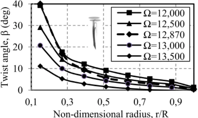
Fig. 7 Optimal twists angle of proprotor blades in cruise at different Ω
Fig. 8 Thrust available and thrust required at different cruise velocity
Fig. 9 Optimal twists angle of proprotor blades in cruise mode at different cruise velocity
(Ω=13,500)
Fig. 10 represents the optimal blade twist distribution in hover and cruise modes that satisfy the design constraint (∆β≤8°) for flexible proprotor. The performance of the rigid proprotor was also computed. As for a rigid proprotor, the optimized blade twist of the flexible proprotor in cruise was chosen as a blade twist of the rigid proprotor, as shown in Fig. 10. The optimized blade geometry of single-point propeller/rotor design in terms of chord and twist angle distribution is shown in Fig. 11. And the performances of the optimized propeller and optimized rotor in cruise and hover respectively were used as a baseline of comparison with the designed proprotor as shown in Table 2.
Fig. 10 Blade geometry of flexible proprotor Fig. 11 Optimal blade shapes at single design
point in hover and in cruise 0 1 2 3 4 12 12,5 13 13,5 T av ai la b le ( N ) Rotational speed, Ω (x103) 0 10 20 30 40 0,1 0,3 0,5 0,7 0,9 T w is t ang le , β (de g ) Non-dimensional radius, r/R Ω=12,000 Ω=12,500 Ω=12,870 Ω=13,000 Ω=13,500 0 0,2 0,4 0,6 0,8 15 20 25 30 T hr us t, T ( N ) Cruise velocity, Vc(m/s) Ω=13100 Ω=13300 Ω=13500 0 10 20 30 40 50 60 0,1 0,3 0,5 0,7 0,9 T w is t ang le , β (de g ) Non-dimensional radius, r/R V=16m/s V=20m/s V=25m/s V=30m/s 0 0,1 0,2 0,3 0,4 0 10 20 30 40 50 0,1 0,3 0,5 0,7 0,9 c/ R T w is t ang le , β (de g ) Non-dimensional radius, r/R 0 50 100 0 0,1 0,2 0,3 0,4 0 0,2 0,4 0,6 0,8 1 T w is t ang le , β (de g ) c/ R Non-dimensional radius, r/R c/R (Cruise) c/R (Hover) Twist (Cruise) Twist (Hover) Thrust required Blade twist of rigid proprotor Treq=1.7N
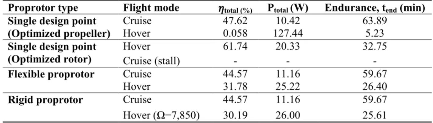
Table 2 Results comparison of propulsion performance between propeller, rotor and proprotor
Proprotor type Flight mode total (%) Ptotal (W) Endurance, tend (min)
Single design point (Optimized propeller)
Cruise 47.62 10.42 63.89
Hover 0.058 127.44 5.23
Single design point (Optimized rotor)
Hover 61.74 20.33 32.75
Cruise (stall) - - -
Flexible proprotor Cruise 44.57 11.16 59.67
Hover 31.78 25.22 26.40
Rigid proprotor Cruise 44.57 11.16 59.67
Hover (Ω=7,850) 30.19 26.00 25.61
The optimized propeller able to hover the MAVion but consumes very high power which reduces the endurance, meanwhile, the optimized rotor stalls the MAVion in forward flight. The optimized rigid proprotor reduces vey slight its performance as compared to the optimized flexible proprotor even though it is needed to be operated at Ω=7,850 to obtain sufficient thrust in hover.
The optimized flexible and rigid proprotor offers ~30% increment of total in hover as compared to
the optimized propeller. It also promises flight endurance at both flight modes as long as the optimized rotor and optimized propeller in hover and forward flight respectively.
Conclusions
A practical and reliable methodology to design the proprotor for the application in tilt-body micro-air-vehicles (TB-MAV) with efficient global propulsion system and long flight endurance
was presented. To acquire maximum total, the proprotor blade was optimized in terms of twist angle
distribution along the blade using MIL condition to obtain the maximum proprotor while the
operating condition was optimized to obtain the maximum motor. The presented efficient design methodology which combines both proprotor and motor design could be used as a practical design tool for the passive control proprotor development.
References
[1] L. Wang-Yu, and Z. Yong, Adaptive Bend-Torsional Coupling Wind Turbine Blade Design Imitating the Topology Structure of Natural Plant Leaves, A.B. Ibrahim, Wind Turbines, InTech Publication, 2011, pp. 52-86.
[2] L. Li, F. Ghrib, and W. Polies, Identification of Stiffness Distribution and Damage in Euler-Bernoulli Beams Using Static Response, International Workshop Smart Materials and Structures, Montreal, 2009.
[3] C. N. Adkins, and R. H. Liebeck, Design of Optimum Propellers, J. Propulsion and Power, 10 (1994) 676 – 682.
[4] M. Drela, XFOIL: An Analysis and Design System for Low Reynolds Number Airfoil, Low Reynolds Number Aerodynamics, edited by T. J. Mueller, Springer–Verlag, New York (1989) 1-12. [5] B. R. Hein, and I. Chopra, Hover Performance of a Micro Air Vehicle: Rotor at Low Reynolds number, J. American Helicopter Society, 52 (2007) 254-262.
[6] E.V. Laitone, Wind tunnel tests of wings at Reynolds numbers below 70,000, Experiments in Fluids 23(1997) 405-409, Sringer-Verlag, 1997.
[7] D.P. Raymer, Aircraft Design: A Conceptual Approach, 3rd, AIAA Education Series, AIAA, Reston, 1999, Chap. 13.