Numerical and Experimental Study of Dynamics and
Vibration Control of Flexible Joint Robots
by
Minh Nha PHAM
THESIS PRESENTED TO ÉCOLE DE TECHNOLOGIE SUPÉRIEURE IN
PARTIAL FULFILLMENT OF THE REQUIREMENTS FOR THE DEGREE
OF DOCTOR OF PHILOSOPHY
PH. D.
MONTREAL, MARCH 2, 2020
ÉCOLE DE TECHNOLOGIE SUPÉRIEURE
UNIVERSITÉ DU QUÉBEC
This Creative Commons license allows readers to download this work and share it with others as long as the author is credited. The content of this work can’t be modified in any way or used commercially.
BOARD OF EXAMINERS
THIS THESIS HAS BEEN EVALUATED BY THE FOLLOWING BOARD OF EXAMINERS
Prof. Zhaoheng Liu, Thesis Supervisor
Department of Mechanical Engineering at École de technologie supérieure
Prof. Ilian Bonev, President of the Board of Examiners
Department of Systems Engineering at École de technologie supérieure
Prof. Antoine Tahan, Member of the jury
Department of Mechanical Engineering at École de technologie supérieure
Prof. Pierre Bélanger, Member of the jury
Department of Mechanical Engineering at École de technologie supérieure
Prof. Youmin Zhang, External Evaluator
Department of Mechanical, Industrial & Aerospace Engineering at Concordia University
THIS THESIS WAS PRENSENTED AND DEFENDED
IN THE PRESENCE OF A BOARD OF EXAMINERS AND PUBLIC FEBRUARY 18, 2020
DEDICATION
ACKNOWLEDGMENT
First of all, I would like to thank my supervisor, Professor Zhaoheng Liu, for his patience, invaluable guidance, and encouragement during this research work. His scientific advice and continuous support help me to overcome all the difficulties through the period of my PhD study.
†I sincerely thank my co-supervisor, Professor Pascal Bigras for his supervision, support, and
constructive suggestions during my work.
My sincere thanks also go to Mr. Bruce Hazel and Mr. Philippe Hamelin, my supervisors at Hydro-Québec Research Institute (IREQ). Their grateful support and insightful comments help me to widen my research from various perspectives. I am also grateful for all the technical help and support from the SCOMPI team at IREQ during my experimental study.
I also would like to thank the jury members for accepting to evaluate my thesis and for their helpful advice to improve this work.
Finally, I acknowledge the financial support from École de Technologie Supérieure, Natural Science and Engineering Research Council of Canada (NSERC), Hydro-Québec Research Institute, and Mitacs through the Mitacs Accelerate program.
Étude numérique et expérimentale de la dynamique et du contrôle des vibrations des robots articulations flexibles
Minh-Nha PHAM
RÉSUMÉ
Les robots sériels sont récemment l'une des méthodes les plus efficaces pour réaliser plusieurs applications industrielles, notamment le positionnement précis et les tâches d'inspection. Ils peuvent fournir une grande enveloppe de travail, un accès à des zones restreintes, des opérations dans des environnements dangereux et des travaux de précision avec un haut degré de fiabilité. Un désavantage majeur des robots sériels est le problème des vibrations, en raison de la dynamique des modes flexibles qui sont excités. La vibration provoque une détérioration de la précision du contrôle de mouvement, une grande contrainte dans les boîtes de vitesses et des déformations ou des dommages du robot manipulateur. La dynamique des modes flexibles est introduite en raison de la faible rigidité des robots manipulateurs, qui peut être causée par la flexibilité des articulations ou des membrures. Indépendamment de la taille et de la conception, la plupart des robots sériels sont encore assez flexibles avec la première résonance dans les basses fréquences d'environ 10 Hz. Pour éviter les conséquences causées par les vibrations, le contrôle des vibrations devient très important et doit être pris en compte dans la conception des contrôles.
L'objectif principal de cette étude est de concevoir des algorithmes de contrôle pour réduire les vibrations des robots sériels avec articulations flexibles. Les procédures de conception de contrôleur proposées peuvent être appliquées à divers robots industriels et sont testées expérimentalement sur un robot industriel à six articulations, le SCOMPI, actuellement en développement à l'Institut de recherche d'Hydro-Québec. Pour atteindre cet objectif, deux phases d'étude sont proposées.
L'objectif de la première phase est d'étudier la dynamique et de concevoir un algorithme de contrôle des vibrations pour un robot à articulation unique. Un modèle dynamique décentralisé de robot sériel avec articulation flexible est étudié. Les concepts de contrôle sont testés sur une configuration expérimentale simple composée d'une seule articulation et d'une seule membrure. Toutes les parties du système sont considérées comme rigides à l'exception d'un élément qui est l’articulation flexible. Le modèle de joint flexible unique est placé dans un environnement entièrement contrôlé, dans lequel l'accès à la commande de couple du moteur, à la référence du moteur ou aux états de rétroaction est disponible. Pour cet objectif, un contrôleur à deux étages amélioré est proposé, qui combine deux parties. La première partie est un contrôleur à deux étages basé sur la commande de backstepping, qui considère la position du moteur comme une entrée de commande virtuelle pour la dynamique côté membrure. La seconde partie est un observateur d'état et de perturbation, qui compense les
X
perturbations et reconstruit les mesures indirectes. La simulation numérique et les résultats expérimentaux valident que le contrôleur proposé améliore efficacement les performances de contrôle en termes de réduction des vibrations des membrures, d'extension de la bande passante et d'atténuation de l'erreur cinématique du réducteur d'entraînement harmonique du joint. Les limites du contrôleur proposé sont également discutées. Les performances de contrôle dépendent des paramètres du système, qui doivent être correctement identifiés. Cela nécessite également des efforts pour régler manuellement les gains du contrôleur. Et surtout, le contrôleur proposé doit avoir accès à la commande de couple du moteur pour implémenter son algorithme. Cependant, il convient de mentionner que les résultats de la première phase valident l'hypothèse de modélisation sous-jacente pour le joint flexible et que l'architecture en deux étages est réalisable à des fins de contrôle des vibrations.
Sur la base des résultats prometteurs du contrôle des vibrations pour le robot à articulation unique, la deuxième phase consiste à adapter les connaissances acquises pour un cas qui est beaucoup plus général, un robot série industriel à articulations multiples. Il y a une décision à prendre, soit qu‘une configuration expérimentale multi-joint est construite, soit qu‘un robot sériel existant est utilisé comme banc d'essai. Avec la première option, le contrôleur développé dans la première phase peut être directement appliqué. Cependant, la construction d'une nouvelle configuration expérimentale multi-joint peut nécessiter beaucoup d'efforts et de temps. La dernière option, utilisant un robot industriel existant comme banc d'essai, présente un gros avantage. Cela coûte beaucoup moins cher car la main-d'œuvre humaine, le matériel pour construire les composantes sont économisés et tous les éléments mécaniques ou électroniques sont inclus. Cependant, le nouveau contrôleur doit se conformer à l'interface de contrôle existante du robot. L'une des contraintes est que le robot est contrôlé en mode position et que l'accès au couple de joint n'est pas disponible. Sans accès à la commande de couple du moteur, le contrôleur proposé pour le robot à articulation unique dans la première phase ne peut pas être directement appliqué.
Dans l'étude de cette deuxième option, un robot industriel sériel à articulations multiples est utilisé pour développer un algorithme de contrôle des vibrations. Bien qu'un nouveau contrôleur doive être développé, il partage toujours certains aspects du modèle dynamique de robot avec articulation flexible développé dans la première phase. De plus, il peut être facilement industrialisé par la suite car toutes les contraintes sont déjà prises en compte. Notez que, en raison du fait que l’accès à la commande de couple du moteur n'est pas disponible, le contrôleur proposé doit être basé sur la commande de position du moteur.
L'objectif de la deuxième phase est de concevoir des algorithmes de contrôle des vibrations pour les robots industriels à articulations flexibles multiples. Un modèle flexible décentralisé est introduit, dans lequel la rigidité de couplage localisée est prise en compte. Dans le premier étage, une entrée à mise en forme variable dans le temps façonne la dynamique de contrôle rigide en une dynamique souhaitée qui ne produit pas de vibrations. Un deuxième étage est ajouté pour augmenter le rejet des perturbations. Un prédicteur de Smith généralisé est développé pour compenser le retard et le filtre passe-bas des capteurs de rétroaction. Des simulations numériques et des expériences sur un robot à six articulations SCOMPI confirment
XI
que le contrôleur proposé améliore les performances de contrôle en termes de bande passante, d'atténuation des vibrations et de rejet des perturbations.
Mots clés: robot articulation flexible, contrôle des vibrations, contrôleur à deux étages, observateur de perturbation, observateur d'état, formation d’entrée variant dans le temps, prédicteur de Smith.
Numerical and experimental study of dynamics and vibration control of flexible joint robots
Minh-Nha PHAM
ABSTRACT
Serial robots are recently one of the most effective methods to realize several industrial applications including precision positioning and inspection tasks. They can provide a large working envelope, access to restricted areas, operations in hazardous environments, and precision works with high degree of reliability. A major issue of serial robots is vibration, due to flexible modes dynamics that are excited. The vibration causes deterioration of motion control accuracy, large stress in the joint gearboxes, and deformations or damages of the robot manipulator. The flexible modes dynamics are introduced due to the low rigidity of robot manipulators, which may be caused by the flexibility of joints or links. Regardless of size and design, most serial robots are still quite flexible with the first resonance in low frequencies of about 10 Hz. To avoid the consequences caused by vibrations, vibration control becomes very important and needs to be taken into account in control design.
The main objective of this study is to design control algorithms to reduce vibration of flexible joint robots. The proposed controller design procedure can be applied for various industrial robots and is tested experimentally on an industrial six-joint robot namely SCOMPI, developed at Hydro-Québec’s Research Institute. In order to achieve that end, two phases of study are proposed.
The objective of the first phase is to study the dynamics of a single flexible joint robot and design a control algorithm to reduce the vibration. Decentralized dynamic model of flexible joint robot is studied. Control concepts are tested on a simple experimental setup consisting of only one joint and one link. All parts of the system are considered rigid except for one element that is the flexible joint. The single flexible joint model is placed in a fully-controlled environment, in which access to motor torque command, motor reference, or feedback states are available. For this objective, an enhanced two-stage feedback controller is proposed, which combines two parts. The first is a two-stage feedback loop based on backstepping control, which considers the motor position as a virtual control input for the link side dynamics. The second is a disturbance-state observer, which compensates disturbances and reconstructs indirect measurements. Numerical simulation and experimental results validate that the proposed controller effectively improves control performance in terms of reducing link vibration, extending control bandwidth, and attenuating the kinematic error from the joint’s harmonic drive reducer. Limitations of the proposed controller are also discussed. The control performance relies on system parameters, which need to be properly identified. It also requires effort to manually tune controller gains. And most importantly, the proposed controller needs access to motor torque command to implement its algorithm. However, it is worth mentioning
XIV
that the results of the first phase validate the underlying modelling assumption for the flexible joint and that the two-stage architecture is feasible for vibration control purpose.
Based on promising results of vibration control on single flexible joint test bench, the second phase is to adapt the acquired knowledge for a much more general case, industrial serial robot with multiple joints. There is a decision to make, either a multi joint experimental setup is built or an existing serial robot is used as a test bench. With the former option, the controller developed in the first phase can be directly applied. However, building a new multi-joint experimental setup costs a lot of effort and time. The latter option, using an existing industrial robot as a test bench, has a big advantage. It costs much less since man power, material to build things are saved and all mechanical or electronic elements are included. However, a new controller must be designed to comply with the existing robot control interface. One of the constraints is that the industrial robot is controlled in position mode and that the access to the motor torque command is not provided. Without access to the motor torque command, the controller proposed for single joint test bench in the first phase can not to be directly applied. Considering these two options, an existing industrial multiple joint serial robot is used to develop vibration control algorithms. Although a new controller needs to be developed, it still shares some aspects of the dynamic model of flexible joint robot developed in the first phase. Also, it can be easily industrialized afterward since all constrains are already taken into account. Note that, due to the fact that access to motor torque command is unavailable, the proposed controller needs to be based on the access to motor position command.
The objective of the second phase is to design vibration control algorithms for industrial robots with multiple flexible joints. A two-stage flexible joint discrete controller is presented, where the decentralized approach is extended with a lumped stiffness to take into account the dominant coupling mode. In the first stage, a time-varying input shaping feedforward shapes the rigid closed-loop dynamics into a desired dynamics that does not produce link vibrations. A second stage is added to increase disturbance rejection. A generalized Smith predictor is developed to compensate for delay and link feedback sensor filtering. Numerical simulations and experiments on a six-joint robot manipulator SCOMPI confirm that the proposed controller improves control performances in terms of bandwidth, vibration attenuation, and disturbance rejection.
Keywords: flexible joint robot, vibration control, two-stage controller, disturbance observer, state observer, time varying input shaping, Smith predictor.
TABLE OF CONTENTS
Page
INTRODUCTION ...1
CHAPTER 1 BACKGROUND AND LITERATURE REVIEW ...5
1.1 Dynamic models of robot manipulators ...5
1.1.1 Rigid manipulators ... 5
1.1.2 Flexible joint robot manipulators ... 6
1.2 Vibration control of flexible joint robot...8
CHAPTER 2 OBJECTIVE AND RESEARCH APPROACH ...13
2.1 Objective of the thesis ...13
2.2 Research approach ...14
CHAPTER 3 A TWO-STAGE FEEDBACK CONTROLLER SUPPORTED BY DISTURBANCE-STATE OBSERVER FOR VIBRATION CONTROL OF A FLEXIBLE JOINT ROBOT ...17
3.1 Introduction ...17
3.1.1 Flexible joint robot control background ... 18
3.1.2 Need for disturbance-state observer ... 20
3.1.3 Purpose and structure of this chapter ... 21
3.2 Modelling of the flexible joint robot ...22
3.3 Rigid control limitation background ...27
3.3.1 Rigid control design ... 28
3.3.2 Bandwidth limitation ... 30
3.4 Enhanced two-stage feedback controller ...31
3.4.1 Two-stage feedback controller design ... 32
3.4.2 Disturbance-state observer design ... 35
3.4.3 Steady-state error analysis ... 40
3.4.4 Closed-loop control bandwidth analysis ... 42
3.4.5 Closed-loop system stability analysis ... 44
3.4.6 Controller synthesis procedure ... 46
3.5 Experiments ...47
3.5.1 Experiment setup ... 47
3.5.2 Identification of the single flexible joint robot ... 48
3.5.3 Controller gain selection ... 50
3.5.4 Simulation and experimental results ... 51
3.6 Summary ...62
CHAPTER 4 VIBRATION CONTROL OF MULTIPLE FLEXIBLE JOINT ROBOTS USING A DISCRETE-TIME TWO-STAGE CONTROLLER BASED ON TIME VARYING INPUT SHAPING AND DELAY COMPENSATION ...63
XVI
4.1 Introduction ...63
4.2 System modelling ...66
4.2.1 Flexible joint robot modelling background... 66
4.2.2 Proposed flexible joint model ... 70
4.3 Controller design ...74
4.3.1 First-stage conventional built-in rigid controller ... 76
4.3.2 First-stage input shaping feedforward ... 77
4.3.3 First-stage time-varying dynamics ... 80
4.3.4 Second-stage PID compensator ... 83
4.3.5 Second-stage feedback filter ... 83
4.3.6 Second-stage generalized Smith predictor ... 84
4.3.7 Discrete-time implementation ... 86
4.3.8 Stability analysis ... 90
4.3.9 Model mismatch sensitivity analysis ... 96
4.3.10 Parameter identification technique ... 98
4.3.11 Multiple joint synchronization ... 102
4.4 Experiment ...103
4.4.1 Experimental setup... 103
4.4.2 Parameter identification ... 107
4.4.3 Validation of the first-stage control performance ... 110
4.4.4 Validation of the second-stage control performance ... 112
4.4.5 Validation of time-varying dynamics ... 116
4.4.6 Validation of end effector vibration attenuation ... 117
4.5 Summary ...121
CONCLUSION…. ...123
RECOMMENDATIONS ...125
APPENDIX I TRANSFORMATION BETWEEN PID AND P/PI COMPENSATORS ...127
LIST OF TABLES
Page
Table 3.1 Single flexible joint robot parameters identified ...50
Table 3.2 Experimental comparison of control performance in terms of step response, control bandwidth and kinematic error compensation ...59
Table 4.1 Joint specifications ...105
Table 4.2 Mass distribution ...105
LIST OF FIGURES
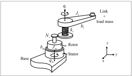
Page Figure 3.1 The single flexible joint robot schematic diagram ...24 Figure 3.2 Rigid control for the single flexible joint robot ...28 Figure 3.3 Block diagram of the closed-loop system using the proposed
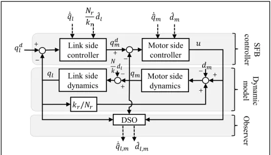
controller ESFB. The link side controller shown in (3.31), the motor side controller shown in (3.24), the link side dynamics shown in (3.2) or (3.30), the motor side dynamics shown in (3.3) and the disturbance-state observer shown in (3.37) and (3.40) ...32 Figure 3.4 Combination of the disturbance-state observer and the
two-stage controller ...36 Figure 3.5 (a) The six-joint SCOMPI robot, (b) The single flexible joint test
bench to test a flexible joint of the SCOMPI robot ...48 Figure 3.6 Comparison of the simulated and the measured open-loop
frequency responses of the single flexible joint robot. (a) The motor position plant q s u s and m( ) / ( )
(b) The link position plant ( ) / ( )q s u s ...49l
Figure 3.7 The experimental identification of the joint friction ...49 Figure 3.8 Simulation: the closed-loop frequency responses using
rigid control (RC) and using enhanced two-stage
feedback control (ESFB) assuming no disturbances ...53 Figure 3.9 Simulation: the closed-loop frequency responses using
rigid control (RC) and using enhanced two-stage feedback
control (ESFB) assuming 30% uncertainty on joint stiffness ...54 Figure 3.10 Experiment: the closed-loop frequency responses using
rigid control (RC) and using enhanced two-stage
feedback control (ESFB) ...55 Figure 3.11 Experiment: the link step response ...57 Figure 3.12 Experiment: the link vibration due to kinematic error of the
harmonic drive reducer ...58 Figure 3.13 Experiment: the link step responses using the enhanced two-stage
feedback control (ESFB) and using the two-stage feedback
XX
Figure 3.14 Experiment: the link velocities of the step response experiment with the proposed enhanced two-stage feedback control (ESFB)
and with the two-stage feedback control (SFB) ...61 Figure 3.15 Experiment: the motor torques of the step response experiment
with the proposed enhanced two-stage feedback control (ESFB)
and with the two-stage feedback control (SFB) ...61 Figure 4.1 Conventional decentralized model of a flexible joint. The joint
model consists of a motor mass and a link mass, connected
via a reducer, which is the only element considered to be flexible ...69 Figure 4.2 Experimental results of vibrations of the link and the reducer
output position. It is unable to simulate the distortion between the link positon and the reducer output position using conventional
decentralized flexible joint model ...69 Figure 4.3 Closed-loop frequency response of a single flexible joint. The
experimental frequency response has a resonance and
an anti-resonance while the simulation frequency response using the conventional decentralized model (CDM) has only a resonance. Varying the reducer stiffness only allows the simulation using CDM matching the frequency of the resonance ...70 Figure 4.4 Proposed schematic diagram of a flexible joint model. The motor
position q and the reducer output position m q can be measured r
directly by encoders ...71 Figure 4.5 Frequency responses of the proposed flexible joint model.
( )
M s is the transfer function from the motor torque to the motor position and R s( ) is the transfer function from the motor
position to the link position ...74 Figure 4.6 Block diagram of the proposed two-stage controller.
( )
M s , R s( ), L s( ), and K s( ) represent time-varying joint
dynamics, depending on robot configurations ...75 Figure 4.7 Phase lag and delay induced by discrete PID distortion at high
frequencies ...89 Figure 4.8 (a) Frequency response of the closed-loop G with and without 1
PID distortion compensation; (b) Zoomed-in of selected
XXI
Figure 4.9 (a) Pole locus of closed-loop model G z with increasing 1( ) λ1, (b) Zoomed-in of region I: delays dynamics,
(c) Zoomed-in of region II: flexible joint dynamics ...91 Figure 4.10 (a) Frequency response and (b) step response of the first-stage rigid
control versus the first-stage input shaping feedforward control ...92 Figure 4.11 Phase margin and closed-loop bandwidth of the two-stage control
with increasing K ...93d2
Figure 4.12 Load disturbance rejection with three controllers: Rigid control,
Input shaping control, and Two-stage control ...94 Figure 4.13 Frequency responses of the sensitivity function of the system
using Two-stage control with and without the second-stage
low-pass filter ...95 Figure 4.14 (a) Frequency response and (b) step response of the first-stage
feedforward control with large modelling errors ...97 Figure 4.15 Phase margin and closed-loop bandwidth of two-stage control
with large modelling errors ...98 Figure 4.16 Frequency identification from experimental data:
(a) Identified from the original signal, (b) Identified from the
time inverse signal ...101 Figure 4.17 Experimental testbed: (a) the industrial six-joint SCOMPI robot
manipulator with embedded joint controllers; (b) the robot
controller and the teach pendant ...104 Figure 4.18 Robot configurations used for identification: (a) Fully extended
pose and (b) Fully folded pose ...108 Figure 4.19 Identification of the effective joint 2 stiffness ...108 Figure 4.20 Comparison of experiment and simulation motor torque
spectrums. (a) Flexible joint dynamics and (b) Delay dynamics ...109 Figure 4.21 Zoomed-in of the regions (a) and (b) shown in Figure 4.20 ...109 Figure 4.22 Experimental and simulation temporal responses of reducer
output position q [rad] with rigid control. Rigid controller gains r
XXII
Figure 4.23 Experimental and simulation motor torque spectrum with rigid controller gains corresponding to (a) λ1=0.5, (b) λ1=2.3,
and (c) λ1=2.8 ...111 Figure 4.24 Experimental and simulation temporal responses of reducer output
position with input shaping control...112 Figure 4.25 Experimental and simulation temporal responses of reducer output
position using two-stage controller with GSP disabled or enabled ...113 Figure 4.26 Experimental and simulation torque spectrum of two-stage
controller with the feedback filter enabled and disabled ...114 Figure 4.27 Experimental and simulation temporal responses with three
controllers: Rigid control, Input shaping control, and Two-stage
control: (a) Experiment, (b) Simulation ...114 Figure 4.28 Experimental and simulation frequency responses with three
controllers: Rigid control, Input shaping control, and Two-stage control; (a) From reference input to reducer output position,
(b) From reference input to link position ...115 Figure 4.29 (a) Overview of the reference trajectory. The robot configuration
changes from (b) large link 2 effective inertia, via (c) average link 2 effective inertia and finishes at (d) minimum link 2 effective side
inertia ...116 Figure 4.30 Experimental temporal responses of joint 2 for trapezoidal trajectory
during configuration change. (a) For large link 2 effective inertia, (b) For average link 2 effective inertia, (c) For minimum link 2
effective inertia ...117 Figure 4.31 Experimental setup for measuring the robot end effector motion ...118 Figure 4.32 Experimental and simulation temporal responses of the end effector
with joint 2 weaving for three controllers: (a) Rigid control, (b) Input shaping control, (c) Two-stage control. The measured Cartesian position signals are converted into an angular joint
position for comparison with the angular reference signal ...119 Figure 4.33 Experimental and simulation temporal responses of the end effector
with joint 3 weaving for three controllers: (a) Rigid control,
XXIII
Figure 4.34 Experimental and simulation temporal responses of the end effector with joint 4 weaving for three controllers: (a) Rigid control,
LIST OF SYMBOLS
Symbol Units Description
0...7
a - Coefficients of denominator of G s 1( ) 0...4
b - Coefficients of numerator of G s 1( )
l
b Nms/rad Link viscous friction
m
b Nms/rad Motor viscous friction
l
B Nms/rad Joint damping matrix
m
B Nms/rad Motor viscous friction matrix )
, ( l l
C q q - Coriolis and Centrifugal matrix
FB
C - Feedback of rigid controller
FF
C - Feedforward of rigid controller
l
d Nm Disturbance on link side
m
d Nm Disturbance on motor side
, ˆ
l m
d Nm Estimated disturbance on link or motor side ,
l m
d Nm Disturbance estimation error
)
l
g(q - Gravitational forces vector
e J kgm 2 Effective inertia l J kgm 2 Link inertia m J kgm 2 Motor inertia m J kgm 2
Motor inertia matrix
c
k kNm/rad Coupling stiffness
j
k kNm/rad Joint effective stiffness
1, 1, 1 p d i
K - Rigid control gains
2, 2, 2 p d i
K - Second-stage PID gains
r
k kNm/rad Reducer stiffness
r
K kNm/rad Reducer stiffness matrix
( )
l l
M q - Link inertia matrix
r
N - Reducer gear ratio
r
N - Gear ratio matrix
l
q rad Link position
m
q rad Motor position
r
XXVI
1 d
T s Delay in rigid control feedback loop
1 fb
T s Delay in motor feedback path
s
T s Sampling time
w
T s Compensated distortion delay
u Nm Motor torque vector
u Nm Motor torque
( )
x n rad Filtered time inverse response vector
j
τ Nm Joint torque vector
z
ω rad/s Anti-resonant frequency
p
ω rad/s Resonant frequency
c
ω rad/s Warping frequency
1 n
ω rad/s Natural frequency of rigid control 2
n
ω rad/s Natural frequency of the second-stage PID ,
lc mc
ω rad/s Cut-off frequencies of low-pass filters 2
ζ - Damping ratio of the second-stage PID
1
ζ - Damping ratio of rigid control
1
λ - Rigid control frequency rate
2
INTRODUCTION
Vibration problem
Serial robots are used extensively in industrial applications including pick and place, assembly, machining, and inspection tasks. This is because serial robots can work on large parts in single operation setup, due to their wider working envelopes. In addition, robots can provide a cost-effective solution, by accurately following arbitrarily complex trajectories and accessing restricted areas. Robots are capable of operating in hazardous environments and delivering precision works with high degree of reliability.
At Hydro-Québec’s Research Institute, a robot named “SCOMPI”, which stands for “Super COMPact Ireq robot” is developed for on-side maintenances and inspections. It is a track-based six-joint serial robot with a total weight of about 33 kg and is designed to access difficult-to-reach locations such as turbine blades and unmovable parts like large hydropower equipment.
A major issue of serial robots in general and of the SCOMPI robot in particular is vibration. Vibration occurs when the trajectories, disturbances, or noises excite flexible modes, which are introduced by the low rigidity of the robot manipulator. The vibration may reduce motion control performance, induce large stress in the gearboxes, deform and damage the robot manipulator. The low rigidity, however, is an inherent natural property of open chain kinematic systems. In some particular cases such as space robotic arms, links can be the major source of compliance as they become longer and slender. For most modern industrial robots, the links are considered fairly rigid and the major source of flexibility comes from the joints. The joint speed reducer, the drive shaft, or the bearings may deflect during torque transmission, resulting in a degradation of the overall stiffness.
2
To increase the stiffness, mechanical stiffening of robot components is an option. A concept of mixing parallel and serial links has been introduced to increase the stiffness of industrial robots with maximum payload above 110 kg, such as Fanuc M-900iB, M-2000iA, or M-410iC robots. However, modification of existing robots is costly and generally requires a lot of effort. It is even almost impossible in some industrial robots, which do not allow modifying any part of the hardware.
Vibration control
Therefore, instead of trying to modify the robot structure, it is desirable to leave it untouched. Alternatively, much research effort has been devoted to design vibration control algorithms that takes into account the flexible dynamics of the robot manipulators. By introducing appropriate control signals, the controller may shape the robot dynamics into a desired dynamics where the vibration due to the flexibility is attenuated. Due to its effectiveness, the vibration control is a key to the robot’s performance in terms of accuracy and speed.
There are several difficulties in the development of vibration control algorithms for flexible joint robots. The presence of flexibility introduces more degrees of freedom, resulting in more complicated dynamic models. In addition, when the control architectures that do not take the flexibility into account are used, the control gains should be small to avoid exciting flexible modes. As a price, the control performance in terms of the control bandwidth (defined by a band of frequencies that the output can track the reference input with a small error) and the disturbance rejection (defined by the effect of the disturbances on the output) are low. Another problem is the configuration-dependent of robot dynamics, which introduces more challenges to the robustness of the controllers. Besides, many constrains of industrial robots also pose more challenges to the development of control algorithms. For example, the SCOMPI robot just provides an access to the motor target position while the access to the motor torque and velocity feedback are totally unavailable. The position feedback is accessible, but it comes
3
with delay and quantization noises. Due to these difficulties, the development of control algorithms, which are practical and suitable for vibration control of the industrial flexible joint robots, is still an open problem.
Organization of this thesis
This thesis focuses on vibration control algorithms for flexible joint robots. The proposed method is then validated by numerical simulations and experiments on the industrial serial robot SCOMPI at Hydro-Québec’s Research Institute. The thesis is arranged into four chapters. Chapter 1 presents the background and literature review on vibration control of flexible joint robot. Chapter 2 presents the main objectives, specific objectives, and methodologies needed to be carried out. Chapter 3 and chapter 4 respectively present technical works on designing vibration control algorithms to meet the specific objectives of this thesis. Numerical simulations and experimental results are presented to validate the effectiveness of proposed controllers in terms vibration attenuation, extending bandwidth, and disturbance rejection. The conclusion and recommendations are provided at the end of this thesis.
CHAPTER 1
BACKGROUND AND LITERATURE REVIEW
This chapter presents a background and literature review on dynamic models of robot manipulators and recent motion/vibration control techniques for flexible joint robots. A discussion on remaining problems is also given at the end of this chapter.
1.1 Dynamic models of robot manipulators
Dynamic models of robot manipulators are reviewed in this section. The dynamic model of robot manipulator is important in several ways. Firstly, appropriate dynamic models can be used to perform numerical simulations of robots. The simulation results predict the behavior of the robots under many different operating conditions. Secondly, the dynamic model can be used as a plant to develop control strategies. Some controllers use the dynamic model to determine their optimal gains while others use it to compute feedforward or compensation parts. In the following, dynamic models of both rigid and flexible joint robots are discussed.
1.1.1 Rigid manipulators
This section presents the equations of motion for a rigid-body serial robot manipulator. The robot manipulator is an open kinematic chain with revolute and prismatic joints. For some applications, such as arc welding or grinding, it is necessary to move the end effector of a manipulator from point to point rapidly and accurately. The dynamics of the manipulator plays an important role in achieving such high-speed and low steady-state error performance. There are two types of dynamics problems: direct dynamics and inverse dynamics. The direct dynamics problem is to find the response of a robot arm corresponding to some applied torque and/or forces. This is useful for simulating the manipulator. The inverse dynamics problem is to find the actuator torques and/or force required to generate a desired trajectory of the
6
manipulator. This formulation of dynamics may be useful for the problem of controlling the manipulator. The problem can be formulated in the joint space or in the Cartesian space. The dynamical equations of motion can be formulated by several methods. One of the most frequently used is the application of the Newton and Euler laws. Newton’s and Euler’s equations are written once for each body of a manipulator, resulting a system of equations with applied forces and constrained forces. Dynamic models can also be derived using Lagrange’s equation of motion or Kane’s method.
The dynamic model of rigid serial robot can be written in the form (Craig, 1989; Tsai, 1999):
( ) (
( ) )
l q ql l +C q ,q ql l l+g ql =u
M (1.1)
where ql is an n× vector of link angular displacement, u is an 1 n× vector of actuator torque, 1
( ) l l
M q is the n n× mass matrix of the manipulator, C q ,q( l l) is an n×1vector of Coriolis and centrifugal terms, and g q( )l is an n× vector of gravity terms. 1
1.1.2 Flexible joint robot manipulators
Joint and link flexibilities introduce additional degrees of freedom, resulting in a much more complex dynamic model than the rigid robot dynamics. Depending on the mechanical design of the robot, the flexibility of joints and links may contribute to the overall flexibility in different ways. For example, in the case of aerospace manipulators with long and slender links, link becomes a major source of flexibility. For general industrial manipulators, the effect of flexible links on the vibration is normally much smaller than that of joints.
In this study, we focus on a robot with flexible joints. The flexible joint robot is modelled as an open kinematic chain having n+ rigid bodies, the base and the 1 n links, interconnected by
n (rotary or prismatic) joints undergoing deflection, and actuated by n electrical drives (Craig, 1989; Tsai, 1999). Each motor is an additional rigid body with its inertial properties. The joint
7
flexibility is modelled by linear torsional spring. All joints are considered to be flexible, though mixed rigid-flexible joints may be encountered in some robots due to the use of different transmission devices. When reduction gearings are present, they are modelled as being placed before the joint deflection occurs (De Luca & Book, 2008).
The dynamic model of flexible joint robot can be obtained using Newton-Euler or Lagrange formulation. The kinetic energy stored by the manipulator is the sum of the kinetic energy due to the links alone and the kinetic energy arising from the rotation of the drive rotor alone (Craig, 1989; Readman & Belanger, 1990b; Tsai, 1999). The complete dynamical model for flexible joints manipulator can be expressed as follows:
1 2 , , ( ) ( ) ( ) ) ( ) ( ) ( ) ( ) ( ( ) l m m m m m l l l l l l l l l T l m l l l V l r l r V + + + + = − − − q q M q S q q C q ,q q C q ,q q S q J q C q ,q q τ g q k q q 0 k q q u τ (1.2)
where ( )S q is an l n n× strictly upper triangular matrix corresponding to the inertial coupling
between motors and links, k is an r n n× diagonal matrix of joint stiffness, and the dissipative terms are: , , ( ) ( ) sgn( ) m l V r l l r l m m l m f V m m = +− − + + q q τ q q q q q D q B D B B q τ (1.3)
where D is an r n n× joint viscosity diagonal matrix, B and l B are respectively m n n× diagonal matrices of link and motor viscous friction, Bf is an n n× diagonal matrix of motor
Coulomb friction, sgn( ) is the sign function.
Spong provides an assumption that the kinetic energy of the rotors is due mainly to their own rotation (De Luca, Farina, & Lucibello, 2005; M. W. Spong, 1987). This implies the inertial
8
coupling between motors and links vanishes, i.e. ( )S ql =0 and 1( l l) m= 2( l l) l =
C q ,q q C q ,q q 0. By ignoring the joint viscosity (Dr =0 ), the complete dynamic model is reduced to a reduce model as follows:
1 1 1 ( ) ( ) sgn( ) ( ) ( ) ( ) r m m m l l l l l l l l l r l m m r r m m f r l − − − + + + − = + + + − = + M q k N 0 q B q N k q q C q ,q q g q B q q J q B N q q u (1.4)
The stability of flexible joint robot dynamics is presented using the theory of singular perturbations in (Mills, 1992).
A remaining problem of the robot dynamic model expressed in Eq. (1.4) is that only the reducer stiffness is taken into account. For a robot manipulator where the flexibility of other components is high, the model of Eq. (1.4) may lack accuracy.
1.2 Vibration control of flexible joint robot
This section presents the most common motion control technologies used for flexible joint robots. Model-based controllers are widely used for flexible joint robots. These controllers are favored to take advantage of the available dynamic models, which can be computed using many techniques such as Newton-Euler or Lagrange formulation. However, an identification process is normally required to obtain accurate values of parameters. Well-known model-based control algorithms for flexible joint robot are listed in the following:
PID control (De Luca, 2000; De Luca & Flacco, 2011; De Luca, Siciliano, & Zollo, 2005; Tomei, 1991b): The PID (proportional-integral-derivative) control has three elements: a proportional term to close the feedback loop, an integral term to assure zero error to constant reference and disturbance inputs, and a derivative term to improve stability and good dynamic response. It is adapted for the flexible joint robot.
9
Feed-forward control: (De Luca, 2000) shows that PD-type control law based on the nominal feed-forward computation is a viable solution for a cheap but effective implementation of a feedback controller for the various motion tasks. In (Lessard, Bigras, Liu, & Hazel, 2014), the authors demonstrated the high performance of feed-forward control compared to rigid control and singular perturbation methods in a specific experiment test rig of flexible joint and single link robot.
Singular perturbation (Lessard et al., 2014; Wilson & Irwin, 1993): The singular perturbation method separates the system into two parts: slow dynamics and fast dynamics. The slow part has a rigid control law that ignores robot flexibility. The fast part, which takes into account the flexibility, is stabilized by linear state feedback.
Adaptive control (Al-Ashoor, Patel, & Khorasani, 1993; An-Chyau & Yuan-Chih, 2004; Elbestawi, Yuen, Srivastava, & Dai, 1991; Ge, Lee, & Tan, 1997; Khorasani, 1991; Lee, Ge, & Wang, 2001; Readman & Belanger, 1990b; Ser Yong, Dawson, Jun, & de Queiroz, 1997; Mark W. Spong, 1989; Yin-Chieh & Jinsiang, 2011): The basic idea of adaptive control is to change the gains or other parameters in the control law according to some on-line algorithm. In this way the controller can “learn” an appropriate set of parameters during the course of its operation. This idea is especially useful for manipulators that are performing repetitive task. Without adaptation the tracking errors are also repetitive. With adaptation, the tracking performance can be improved through successive repetition.
Robust control (D.-W. Gu, 2005; Jae Young, Je Sung, & Jong Hyeon, 2007; Kwan & Yeung, 1993; Mark W. Spong, 1989; Tae-Jun, Jaeyoung, & Jong Hyeon, 2007; Yeon, Yim, & Park, 2011): robust control techniques are based on worst case estimates of the uncertainty or mismatch between the plant and the inner loop control. In these approaches the inner loop control law is fixed and the gains in the outer loop are set according to the estimate of the uncertainty.
10
Backstepping approach (J. H. Oh & Lee, 1997): This approach considers joint elastic torque or motor position as an intermediate virtual input to control the link dynamics. The backstepping control is favored to take advantage of the available dynamic models including the joint flexibility. Both motor and link side feedback are used in the control architecture.
In recent years, model-free control has been proposed for flexible joint robots. An advantage of these control techniques is that they do not require a precise system model in the design of the controller. However, they normally need data to train their networks and several iterations to improve control performance. Some literatures are listed in the following:
Fuzzy PID control (Botsali, Kalyoncu, Tinkir, & Onen, 2010; Malki, Misir, Feigenspan, & Guanrong, 1997): authors proposed the mathematical principle for the fuzzy PID controller design, including the fuzzification, rule-base and defuzzification. In this design, a standard PD+I controller configuration is conducted. The design of the fuzzy PID controller consists of two parts: one fuzzy PD and one fuzzy I controllers.
Neural network control (Chatlatanagulchai & Meckl, 2005; Ge et al., 1997; Hunmo & Parker, 1993a, 1993b; Miao & Wang, 2013; Shipitko & Zmeu, 2003; Yeşildirek, Vandegrift, & Lewis, 1996): In (Chatlatanagulchai & Meckl, 2005), authors derive a desired control law based on Lyapunov’s equations. Then, a three-layer neural network is proposed to learn unknown parts of the desired control laws. However, the time-varying case such as the change in payload has not been fully covered in this research.
Iterative learning control: Iterative learning control is a data-driven methodology that iteratively uses the error profile from previous trails to compute the system inputs for the next iteration (W. Chen & Tomizuka, 2014). Normally, the iterative learning control performs as an add-on feedforward controller in addition to the existing time feedback controller, to further enhance the performance over the standalone real-time feedback system. A drawback of iterative learning control is that it requires the
11
system to perform repetitive tasks under the same conditions. This assumption may be invalid if the robot follows arbitrary trajectories under effect of different disturbances.
Control techniques mentioned above normally require access to motor torque command. This requirement becomes an issue for many industrial robots, in which robot joints are equipped with built-in motion controller and no access to motor torque command is provided. In that case, input shaping of the reference profile is an effective technique to reduce vibration. As explained in (Singhose, 2009), input shaping reduces vibration of closed-loop dynamic systems by optimizing only position command signals such that they does not excited flexible modes. The shaped command signal is obtained by convolving the command signal with a sequence of impulses, known as an input shaper. Parameters of the input shaper directly relies on the natural frequencies and damping ratios of the induced vibration.
Based on the literature review, there are some important points that require more attention. The first concern is the flexible joint robot modelling. Recently, the robot dynamic model including flexible dynamics is presented. However, for simplicity, this model only takes the reducer stiffness into account while ignoring the coupling stiffness and the distortions of all other parts of the robot manipulator. To better model the behaviors of the robot manipulators with high coupling stiffness, a dynamic model including the coupling dynamics is necessary to be developed.
The second point is on the control of flexible joint robots. Based on the review of recent techniques, the following observations are drawn:
Backstepping approach is a promising approach for motion and vibration control. No additional devices such as joint torque or acceleration sensors are needed. However, experimental study of backstepping approach is limited since the motor torque signal is very noisy. The performance of this method also relies on the knowledge of parameters, which are difficult to be precisely identified. Due to these difficulties, an
12
application of backstepping approach on flexible joint robot has not been fully developed in recent publications.
Input shaping is an effective method to reduce vibration of system with limited access to the motor torque command. However, how it can be used in combination with the state feedback for industrial serial robots has not been fully detailed in previous literature.
CHAPTER 2
OBJECTIVE AND RESEARCH APPROACH
Based on the literature review, the objective and corresponding methodologies of this thesis are given in this chapter.
2.1 Objective of the thesis
Main objective:
The main objective of this work is to design control algorithms to reduce vibrations while improve control bandwidth and disturbance rejection of flexible joint robots. The control algorithms need to be robust to the changes of the robot’s configurations. The control methods are expected to be practical, which can be retrofitted into industrial robots with limited access to feedback and command signals.
The effectiveness of the proposed approaches is verified by numerical simulations and experiments. Even though this study is validated using a specific robot, namely SCOMPI developed at Hydro-Québec’s Research Institute, the proposed controller design procedures can be used as a practical guideline for various other industrial robots.
Specific objectives:
The main objective is broken down into a series of smaller objectives with intermediate validation. These two specific objectives are given in the following:
Specific objective 1: The first specific objective is to study dynamics and to develop a vibration
control algorithm for a single flexible joint robot using a simple and well controlled testbed. The single joint testbed is designed such that all other components are much more rigid than the joint’s harmonic drive reducer. A full control environment is provided, in which access to motor torque and reference profile is available. The goal of this phase of study is to find how, with this simple testbed, the vibration of a flexible joint can be attenuated.
14
Specific objective 2: The second specific objective is to study dynamics and to develop a
control algorithm for multiple flexible joint robots. Control algorithm developed in this phase is expected to be practical, which can be consequently applied into recent industrial robots.
2.2 Research approach
The research approach used to conduct this research work is briefly discussed in the following:
For the first specific objective, a single flexible joint testbed is built to test control algorithms. A single flexible joint testbed can be built by connecting a rigid rotor and a rigid link via a harmonic drive reducer, which is considered flexible. A motion control drive providing access to motor torque command is used. A vibration control algorithm based on a two-stage feedback controller combined with dual observer is presented. The first part of the controller is a two-stage feedback loop, which considers the motor position as a virtual control input for the link side dynamics. The second is a disturbance-state observer, which compensates disturbances and reconstructs indirect measurements. Numerical simulation and experimental results on a flexible joint robot show the effectiveness of the proposed controller in terms of position tracking, link vibration and rejection of the kinematic error from the joint’s harmonic drive reducer. The first objective is conducted during the first phase of this study. Details of the proposed controller are discussed in chapter 3.
Based on promising results of vibration control on the single flexible joint, the second phase is to develop vibration control algorithm for industrial serial robot with multiple flexible joints. There are two ways to establish a testbed for controller development. The first is to build a new multiple joint experimental setup, in which each joint uses the single flexible joint architecture developed in the first phase. The second is to employ an existing serial robot as a test bench. A main advantage of the former option is that the controller developed in the first phase can be directly applied. However, building a new multi-joint experimental setup costs a lot of effort and time. A big advantage of the latter option, using an existing industrial robot as a test bench,
15
is that it costs much less since man power are saved and all mechanical or electronic elements are already included. However, a disadvantage is that industrial robot may come with several constrains in terms of the access to its software. Industrial robots are normally controlled in position mode and an access to the motor torque reference is not provided. Without the access to the joint torque command, the controller proposed for the single joint test bench in the first phase can not to be directly applied.
Considering these two options, an existing multiple joint serial robot is selected to develop vibration control algorithm. With the option selected, a new controller based on the access to the motor position command is developed. Although the control algorithm developed in the first phase cannot be directly applied, the understanding of the dynamic model of flexible joint robot can be reused. A benefit of developing controller directly for industrial robots is that the controller can be easily industrialized afterward since all constraints are already taken into account.
A vibration control study for an industrial multiple flexible joint robot is conducted in the second phase of this study. A two-stage flexible joint controller based on input shaping is proposed. The decentralized modelling approach for flexible joint is extended with a lumped stiffness to take into account the dominant coupling mode. The proposed controller can be retrofitted into existing robots, for which access to motor torque command is unavailable. Numerical simulations and experiments on a six-joint robot manipulator confirm that the proposed controller improves control performances in terms of bandwidth, vibration attenuation, and disturbance rejection. Details of the proposed controller are discussed in chapter 4.
CHAPTER 3
A TWO-STAGE FEEDBACK CONTROLLER SUPPORTED BY DISTURBANCE-STATE OBSERVER FOR VIBRATION CONTROL OF A FLEXIBLE JOINT
ROBOT
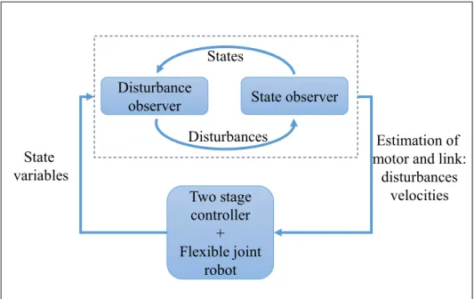
The performance of robot manipulator is limited due to the presence of the joint flexibility, which introduces additional degrees of freedom to the robot dynamic model and additional vibration modes. To overcome these problems, this chapter introduces an enhanced two-stage feedback controller, which is a combination of two subsystems. The first subsystem is a two-stage feedback control, in which the motor position is considered as a virtual control input of the link side dynamics. The second subsystem is a dual observer, which combines a disturbance observer and a state observer. The dual observer compensates disturbances and estimates the feedback signals that could not be measured directly. To validate the effectiveness of the proposed controller, numerical simulations and experiments on a single flexible joint testbed are conducted. The simulation and experimental results show that the control preformation are improved significantly in terms of link vibration, position tracking, and rejection of the kinematic error due to harmonic drive reducers. This chapter is based on an article titled “A Two-Stage State Feedback Controller Supported by Disturbance-State Observer for Vibration Control of a Flexible-Joint Robot” published on Robotica (in press), accepted in July 2019.
3.1 Introduction
Serial robots are used in several industrial applications. The control performance is reduced mainly by vibration problems, which are caused by the presence of joint flexibility. Since the joint flexibility induces a distortion between motor and link positions, a single joint becomes a multiple degrees of freedom system with a complex dynamic model. The joint flexibility introduces flexible modes, which may be excited by the reference or disturbances such as external torques, coupling torques, or kinematic error frequencies if harmonic drive reducers are used at robot joints (Gandhi & Ghorbel, 2002; Tonshoff & Kummetz, 1999).
18
In order to avoid exciting flexible modes, the control bandwidth of flexible joint robots is kept lower than a half the lowest flexible frequency (Craig, 1989). The low control bandwidth, however, may significantly deteriorate the robot control performances in terms of vibration control, motion control, and disturbance rejections. Although many studies on control algorithms for flexible joint robots has been conducted, extending robot control bandwidth while minimizing the effect of kinematic error with experimental validation on flexible joint robots is still open for further research.
3.1.1 Flexible joint robot control background
Most industrial serial robots currently use a decentralized control approach, in which the robot joints are controlled individually using joint-level controllers (Houman Dallali, Lee, Tsagarakis, & Caldwell, 2015). The decentralized approach is based on an idea that that the multiple joint robot dynamic model can be decoupled into multiple single-joint systems. The nonlinear terms and coupling effects are grouped into lumped disturbances (Cong Wang, Zheng, Wang, Peng, & Tomizuka, 2017). These disturbances are considered substantially small and treated independently by joint-level controllers, resulting in stable and good control performance (W. Chen & Tomizuka, 2014). Due to the success of the decentralized control approach, most studies including the study in this chapter focus on a development of joint-level controllers for the decoupled single-joint model.
Several methods for motion control in joint-level of flexible joint robots are well documented in (M.W. Spong, 1990). The first approach is rigid controller, which is still extensively used for recent industrial serial robots. The proportional-integral-derivative (PID) controller for flexible joint robots are studied in (Nanos & Papadopoulos, 2015; Pham & Ahn, 2014). Another approach is singular perturbation control, in which the flexible joint robot dynamics is approximated by a singular perturbation model (Liu & Huang, 2018; Readman & Belanger, 1990a). A problem of the rigid, the PID, and the singular perturbation control algorithms is that they work only when the flexible mode frequencies are very high in comparison with the dominant frequencies of the transient response. In other word, the robot dynamics can be
19
separated into fast and slow dynamics, which are well separated from each other. However, that frequency separation is not always fulfilled in industrial serial robots. For example, even big serial robots with very high joint stiffness normally carry heavy links and loads, resulting in relatively low flexible mode frequencies. Another reason preventing the extension of the singular perturbation method is that the fluctuation and saturation problems of the control effort, which may damage the test bench (Lessard et al., 2014). The combination of feedback and feedforward control are proposed for flexible joint robots in (Bang, Shim, Park, & Seo, 2010; Losey, Erwin, McDonald, Sergi, & O’Malley, 2016; Yamada et al., 2015). In (Bang et al., 2010), although the control architecture is practical, the feedforward gains are obtained based on a complicated backstepping procedure, making implementation not a trivial matter. The feedforward control approach in (Yamada et al., 2015) provides acceptable motion tracking performance and the closed-loop control bandwidth of about half of the minimum flexible mode frequency. However, the method still requires an experimental validation and more efforts to deal with noises and modeling errors. Another control method for flexible joint robots is iterative learning control, which is discussed thoroughly in (W. Chen & Tomizuka, 2014; Cong Wang et al., 2017; L. Wang, Freeman, & Rogers, 2016; Xu, Chu, & Rogers, 2014). The iterative learning control is suitable for robotic systems performing repetitive tasks under unchanged conditions. The input and the tracking error of the recent iteration are used to construct the input for the next iteration. As a result, the tracking error is decreased proportionally to the iteration number. Another successful control approach for flexible joint robots is feedback linearization, which is discussed in (Nanos & Papadopoulos, 2015). By providing a nonlinear state feedback law, a closed-loop system of flexible joint robots with exactly linear behavior and decoupled dynamics is achieved. However, the feedback linearization may be sensitive to model mismatches since it relies on the exact cancellation of the robot dynamics (Giusti, Malzahn, Tsagarakis, & Althoff, 2017).
Another control method for flexible joint robot is backstepping control, which is also known as two-stage feedback control approach. The two-stage feedback control considers the joint elastic torque or the motor position as an intermediate virtual reference for the link dynamics. When the joint elastic torque is sensed using a torque sensor, the joint elastic torque is
20
considered as a state variable and is controlled by a torque feedback loop (Lin & Goldenberg, 1995). In (Baspinar, 2011), a two-stage feedback controller is proposed, assuming that the robot links converge to their reference motions if the motors track appropriate trajectories. However, most two-stage feedback controllers have been proven only by numerical simulations in recent studies (Baspinar, 2011; Jong H. Oh & Lee, 1999; Sungha Kwon, 2016). The two-stage feedback control approaches, to the authors’ knowledge, has undergone fairly limited testing. This is primarily because of the natural complexity of the flexible joint robot dynamics. For example, although a two-stage feedback control obtains acceptable motion control performance in terms of position tracking error (Uh, Oh, & Lee, 1998), the applied torque on the motor is too noisy. Moreover, complex adaptive schemes proposed by Baspinar may require to deal with uncertainties. The two-stage feedback control approach proposed by (An-Chyau & Yuan-Chih, 2004) was proven to be effective, however, the joint stiffness coefficient selected for simulations was unrealistically low for most recent robotic configurations. Consequently, due to the remaining problems, the recent two-stage feedback controllers developed in the literature cannot be directly applied to actual flexible joint robots. More experimental investigations need to be conducted to validate the performance of the two-stage feedback control approaches. However, despite the practical difficulties mentioned above, the two-stage feedback approach is still very promising since the closed-loop dynamic model is explicit and the control performance can be expressed by analytical solutions.
3.1.2 Need for disturbance-state observer
Most controller mentioned in the previous section are model-based control approaches. The main obstacles that limit the performance of the model-based control algorithms are disturbances and the lack of state measurements. The disturbances may include external torques, kinematic errors, unmodelled joint friction, unmodelled joint stiffness, or parametric uncertainties. A common method to deal with disturbances is disturbance observers. The disturbance observers estimate unknown disturbances in real-time and then cancel them through an appropriate torque feedback loop. General principle of the disturbance observers is presented in (M. Chen & Ge, 2013; Hamelin, Bigras, Beaudry, Richard, & Blain, 2014; S.-K.
21
Kim, Park, Yoon, & Lee, 2015). Active disturbance rejection control is another approach to compensate disturbances (Han, 2009; Parvathy & Daniel, 2013; Zhao & Guo, 2015). Similarity analysis of disturbance observer and active disturbance rejection control are presented in (Y. Wang, Tian, Dai, Shen, & Jia, 2018). A recent work of using the disturbance observers on flexible link systems is discussed in (Morales, Feliu, & Jaramillo, 2012). Morales introduces a disturbance cancellation to only the outer feedback loop, which is the link side dynamics. In (M. J. Kim & Chung, 2015), a disturbance compensation is presented to the inner loop, which is the motor feedback loop of a flexible joint system. However, a disturbance observer on both link and motor sides of flexible joint robots has not been fully developed.
To deal with the lack of feedback signal, the disturbance observer can be combined with state observer, resulting in a dual disturbance-state observer. Although the disturbance-state observer is successfully implemented on several mechanical systems (W. Chen, Yang, Guo, & Li, 2016; Hamelin, Bigras, Beaudry, Richard, & Blain, 2012; Yang, Chen, Li, Guo, & Yan, 2017), a combination of the disturbance-state observer and the two-stage feedback controllers to enhance motion control of flexible joint robots is still a very open problem.
3.1.3 Purpose and structure of this chapter
As discussed in the previous section, the major problems of the conventional two-stage feedback controller applied to flexible joint robots may include very noisy applied motor torques, the effect of uncertainties, and the lack of experimental validations. In order to deal with these problems, this chapter presents a design concept and an experimental study of a two-stage feedback controller supported by a disturbance-state observer to improve control performance in terms of motion tracking and vibration rejections. The two-stage feedback controller is designed based on a backstepping approach. Especially, partitioned controllers are employed on the motor and link side controllers. To support the two-stage feedback controller, a disturbance observer is added to compensate the unwanted disturbances on both the motor side and link side dynamics. In combination with the disturbance observer, a state observer is implemented to estimate the velocity feedback signals. The state observer aims to achieve the