SYNTHESIS AND CHARACTERIZATION OF
NANOPOROUS MATERIALS:
NANOZEOLITES AND METAL-ORGANIC FRAMEWORKS
Thèse
Thanh Vuong Gia
Doctorat en Génie Chimique
Philosophiae Doctor (Ph.D)
Québec, Canada
© Thanh Vuong Gia, 2013
Résumé
Dans ce travail, deux types de nanomatériaux poreux ont été obtenues: des nanozéolithes et des matériaux à réseau organométallique (MOF). Pour les nanozéolithes, deux nouvelles méthodes de synthèses ont été développé: une méthode à phase unique et une méthode biphasique. Dans la méthode à phase unique, une quantité du gel-zéolithique est ajoutée à une solution de toluène/n-butanol contenant l‟agent silylant organosilane. Après 12 heures à 60oC, une phase homogène est obtenue. Ce mélange est traité hydrothermalement pour produire une nanozéolithe fonctionalisée. En revanche, la méthode de synthèse à deux phases, implique l‟introduction de l‟organosilane mélangé à un solvant organique dans le gel de zéolithe aqueux conduisant ainsi à un mélange biphasique. Après mélange et traitement hydrothermal, des nanozéolithes fonctionalisées par silylation sont obtenu dans la phase organique et de larges cristaux de zéolithes sont obtenus dans la phase aqueuse. En principe, les deux méthodes utilisent l‟organosilane pour empêcher la croissance des cristaux. Le solvant organique joue le rôle de dispersant des nanozéolithes fonctionalisées avec l‟organosilane à partir de la phase aqueuse, et contrôle le processus de croissance des nanozéolithes. Ces deux méthodes de synthèse sont applicables autant aux zéolithes MFI que FAU, telles que silicatite-1, ZSM-5 et NaY. Elles peuvent être étendues à la synthèse d‟autres types de zéolithes. L‟activité catalytique de ces nanozéolithes a été évaluée pour le craquage de FCC. Les résultats indiquent que la nanozéolithe de type FAU montre une bonne activité dans cette réaction.
Pour l‟étude des matériaux à réseau organométallique (MOF), une nouvelle approche a été développé pour la synthèse de MIL-88B en utilisant un cluster neutre de métaux mixtes bimétalliques Fe2Ni(µ3-O). Les clusters occupent les nœuds du réseau
MIL-88B à la place du mono-métal Fe3 (µ3-O) avec un anion compensateur. Ce dernier est le
cluster formant le réseau du Fe3MIL-88B non-poreux qui est obtenu par la méthode
conventionnelle. De ce fait, en absence des anions compensateurs dans la structure, Fe2Ni
MIL-88B devient un matériau poreux. De plus, avec la combinaison de la flexibilité de MIL-88B et des métaux mixtes comme nœuds dans le réseau, la porosité peut être contrôlée par échange avec des ligands terminaux du réseau. Ceci nous a permis de moduler d‟une
manière réversible la porosité de MIL-88B à différents niveaux, ainsi que la surface spécifique et le volume de pores dépendant de taille de ligands échangés. Le mécanisme de synthèse a été aussi étudié pour les matétiaux Fe3-MIL88B et Fe2Ni-MIL88B. Les résultats
montrent que pour la synthèse de Fe3-MIL88B, le mono-métal Fe3-MOF-235 est comme le
précurseur pour la formation de MIL-88B. Dans le cas d‟utilisation de métaux mixtes Fe2Ni(µ3-O), les mono-métal Fe3-MOF-235 est formés en premier lors de la synthèse du
métal mixte Fe2Ni-MIL88B. Il est montré que la présence de l‟anion FeCl4-est déteminante
dans la formation de la phase initiale MOF-235 et dans le succès de la synthèse du MIL-88B mono- ou bimétallique
L‟anion FeCl4- est très important pour le succès de la formation de MOF-235. Un
Abstract
In this thesis, two types of nanoporous materials: nanozeolites and metal-organic frameworks were studies. For nanozeolites, two novel methods e.g. single-phase and two-phases were reported for the synthesis of nanozeolites. In the single-phase synthesis method, a proper amount of zeolite gel solution was added to a toluene/n-butanol solution containing an organosilane. After 12 hours at 60oC, a single phase mixture was obtained. This mixture was then subjected to hydrothermal crystallization to produce uniform functionalized nanozeolites. In contrast, the two-phase synthesis method involved the introduction of an organic solvent containing organosilane to the aqueous zeolite gel solution, resulting in a two-phase mixture. Upon mixing and hydrothermal treatment of this mixture, organosilane-functionalized nanozeolites were obtained in the organic phase whereas, large zeolite crystals were found in the aqueous phase. In principle, both methods employed the use of organosilane to inhibit the crystal growth. The organic solvent acted as the medium for the dispersion of nanozeolites functionalized with organosilane from the aqueous phase, which led to the complete halt of the growth process. These two methods were demonstrated to be applicable to the synthesis of MFI and FAU nanozeolites such as silicalite-1 and NaY, and could be applied to the synthesis of other types of zeolites. Catalytic activity of the synthesized nanozeolites was evaluated by the cracking reaction of FCC feed. The result showed that FAU nanozeolites can be good catalysts for the cracking reaction.
For the study of the metal-organic frameworks (MOF), a new rational approach was developed for the synthesis of mixed metal MIL-88B metal organic framework based on the use of neutral bimetallic cluster, such as Fe2Ni(µ3-O) cluster. Unlike the conventional
negative charged single metal cluster, the use of neutral bimetallic cluster as a framework node avoids the need of compensating anion inside porous MIL-88B system; thus such a bimetallic MIL-88B becomes porous. The flexibility of the mixed metal MIL-88B can be controlled by terminal ligands with different steric hindrance. This allows us to reversibly customize the porosity of MIL-88B structure at three levels of specific surface area as well as the pore volume. Synthesis mechanism was also studied. It was found that the
monometallic Fe3-MOF-235 is the precursors to the formation of MIL-88B. MOF-235
comes first then later transforms to Fe3-MIL-88B or acts as seeds for the formation of
mixed Fe2Ni-MIL88B. FeCl4- anion is very important to the successful formation of
List of Contents
Résumé ... iii
Abstract ... v
List of Contents ... vii
List of Tables ... x List of Figures ... xi Acknowledgement ... xv Preface ... xvi Chapter 1. Introduction ... 1 1.1. Zeolite ... 1 1.1.1. Background ... 1 1.1.2. Structure ... 2
1.1.3. General Properties of Zeolites ... 5
1.1.4. Applications ... 6
1.2. Nanozeolites ... 7
1.2.1. Background ... 7
1.2.2. Synthesis ... 8
1.2.3. Recent advances in application of nanozeolites ... 26
1.3. Metal-organic frameworks ... 29
1.3.1. Background ... 29
1.3.2. Design principles of MOFs ... 33
1.3.3. Synthesis ... 36
1.4. Some applications of MOFs ... 38
1.4.1. Adsorption ... 38
1.4.2. MOF as catalysts ... 45
References ... 53
Chapter 2. Experimental ... 61
2.1. Synthesis ... 61
2.1.1. Preparation of clear zeolite gel solution ... 61
2.1.2. Synthesis of nanozeolites using clear gel solution in aqueous medium (conventional method) ... 62
2.1.3. Synthesis of nanozeolites in organic medium... 63
2.1.4. Preparation of silica containing nanozeolites ... 65
2.1.5. Synthesis of MIL-88B metal-organic framework ... 65
2.2. Characterization ... 66
2.2.1. FTIR Spectroscopy ... 66
2.2.2. Raman spectroscopy ... 68
2.2.3. UV-Vis spectroscopy ... 68
2.2.4. Energy-dispersive X-ray spectroscopy ... 71
2.2.5. X-ray Diffraction (XRD) ... 71
2.2.6. 29Si Magic Angle Spinning Nuclear Magnetic Resonance Spectroscopy (MAS NMR) ... 73
2.2.7. Scanning electron microscope (SEM) ... 74
2.2.8. Transmission Electron Microscope (TEM) ... 75
2.2.10. Cracking reaction ... 78
References ... 79
Chapter 3. A New Route for the Synthesis of Uniform Nanozeolites with Hydrophobic External Surface in Organic Solvent Medium ... 81
Résumé ... 81
Abstract ... 81
References ... 88
Supporting information ... 89
Chapter 4. Synthesis of Silylated Nanozeolites in the Presence of Organic Phase: Two-Phase and Single Two-Phase Methods ... 95
Résumé ... 95
Abstract ... 95
4.1. Introduction ... 96
4.2. Experimental ... 99
4.2.1. Synthesis of silylated silicalite-1 using the two phase and single-phase methods ... 99
4.2.2. Two-phase method ... 99
4.2.3. Single-phase method ... 100
4.2.4. Conventional method (synthesis of nanozeolites in aqueous medium) ... 101
4.2.5. Characterization ... 101
4.3. Results and discussion ... 102
4.4. Conclusion ... 113
Acknowledgments ... 114
References ... 115
Chapter 5. Synthesis of Nanozeolite-Based FCC Catalysts and their Catalytic Activity in Gasoil Cracking Reaction ... 117
Résumé ... 117
Abstract ... 118
5.1. Introduction ... 119
5.2. Materials and methods ... 121
5.2.1. Synthesis of nanofaujasite ... 121
5.2.2. Synthesis of nanofaujasite-based FCC catalysts ... 121
5.2.3. Characterization ... 121
5.2.4. MAT cracking evaluation ... 122
5.3. Results and discussion ... 123
5.3.1. Synthesis of nanozeolites ... 123
5.3.2. Synthesis of FCC ... 133
5.3.3. Catalytic test ... 136
5.4. Conclusion ... 144
References ... 146
Chapter 6. Synthesis and Engineering Porosity of Mixed Metal Fe2Ni-MIL-88B Metal-Organic Framework ... 149 Résumé ... 149 Abstract ... 149 6.1. Introduction ... 150 6.2. Experiments ... 154 6.3. Results ... 155
6.3.1. Synthesis of Mixed Metal Fe2Ni-MIL-88B with Different Terminal Ligands . 155
6.3.2. Reversible Breathing Control Using Terminal Ligand ... 159
6.3.3. Adsorption Analysis ... 160
6.4. Discussion ... 163
6.5. Conclusion ... 167
Refrences ... 168
Supporting information ... 170
Chapter 7. Direct Synthesis and Mechanism for the Formation of Mixed Metal Fe2 Ni-MIL-88B ... 185 Résumé ... 185 Abstract ... 185 7.1. Introduction ... 186 7.2. Experimental Section ... 187 7.3. Results ... 188 7.4. Discussion ... 194 7.5. Conclusion ... 198 References ... 199 Supporting Information ... 219 Chapter 8. Conclusion ... 233 List of Pulications ... 239
List of Tables
Table 1.1. Molecular sieve types synthesized in nanosized form, synthesis conditions, and
crystal size[9] ... 16
Table 2.1. Structure insensitive and sensitive framework vibrations of zeolites [4] ... 67
Table 2.2. FTIR band assignment in the wavenumber 400 – 800 cm-1 ... 67
Table 4.1. Physico-chemical properties of the calcined silylated nanozeolite and zeolite samples prepared from the same clear zeolite gel, using different methods: the two-phase, single-phase and conventional methods. ... 102
Table 5.1. Physicochemical properties of nanofaujasite samples. ... 133
Table 5.2. BET analysis of nanozeolite-based FFC catalyst samples. ... 134
Table 6.1. IR analysis of the MIL-88B samples ... 156
Table 6.2. Crystal parameters of the Fe2Ni-MIL-88B samples ... 158
Table 6.3. Porosity of Fe2Ni-MIL-88B ... 163
Table 7.1. FTIR band assignment in the wavenumber 400 – 800 cm-1 ... 217
Table 7.2. Raman band assignments ... 217
Table 7.3. Fe and Ni atomic percentages calculated from EDS spectra ... 217
List of Figures
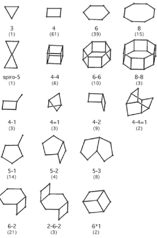
Figure 1.1. Secondary building units and their symbols. Number in parenthesis indicates
frequency of occurrence ... 3
Figure 1.2. (a) MFI and (b) FAU structures ... 4
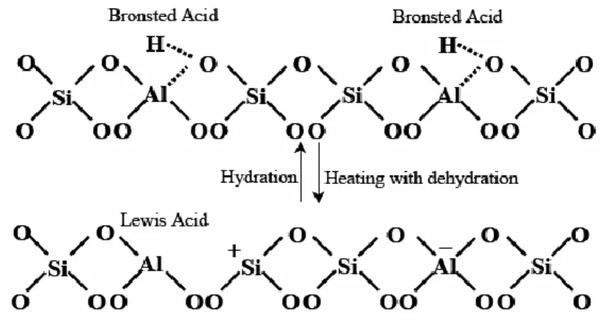
Figure 1.3. Inter-conversion of Brönsted and Lewis acid sites ... 5
Figure 1.4. Calculated surface to bulk atom ratios for spherical nanocrystals[13] ... 8
Figure 1.5. Synthesis of nanozeolites from clear solutions [18] ... 9
Figure 1.6. Two pathways of zeolite formation ... 10
Figure 1.7. A scheme for the crystallization mechanism of silicalite-1[28] ... 12
Figure 1.8. The "nanoslab" hypothesis: (a) the precursor unit containing one TPA cation and (b) schematic representation of nanoslab formation by aggregation of precursor units, as determined by XRS and GPC [32] ... 12
Figure 1.9. Nucleation and growth model of zeolite A and zeolite Y as represented by TEM [34, 35] ... 13
Figure 1.10. Schematic illustration of the mechanism proposed for nanoparticle evolution and crystal growth by aggregation. ... 14
Figure 1.11. Schematic illustration of confined space synthesis.[101]... 21
Figure 1.12. Schematic representation of synthesis of template-free zeolite nanocrystals by using in situ thermoreversible polymer hydrogels.[104] ... 23
Figure 1.13. Schematic representation of revered microemulsion ... 24
Figure 1.14. Schematic representation of microemulsion-microwave synthetic method[115] ... 26
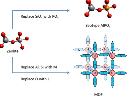
Figure 1.15. Rational design of zeotype and MOF from the basis of zeolite ... 29
Figure 1.16. Crystal structure of HKUST-1 (left) and MOF-5 (right) ... 31
Figure 1.17. Number of metal–organic framework (MOF) structures reported in the Cambridge Structural Database (CSD) from 1978 through 2006. The bar graph illustrates the recent dramatic increase in the number of reports, while the inset shows the natural log of the number of structures as a function of time, indicating the extraordinarily short doubling time for MOF structures compared to the total number of structures archived in the database.[129] ... 32
Figure 1.18. Two geometrically different but topologically identical nets. ... 34
Figure 1.19. MOF-5 structure from linking octahedral SBUs ... 35
Figure 1.20. Design of MOF-5 from simple fcc structure ... 36
Figure 1.21. Structure of NU-100 and its linker ... 40
Figure 1.22. The two different linkers used in MOF-210 (left) and the crystal structure of MOF-210 displaying its unique topology with two different types of pores (right). ... 40
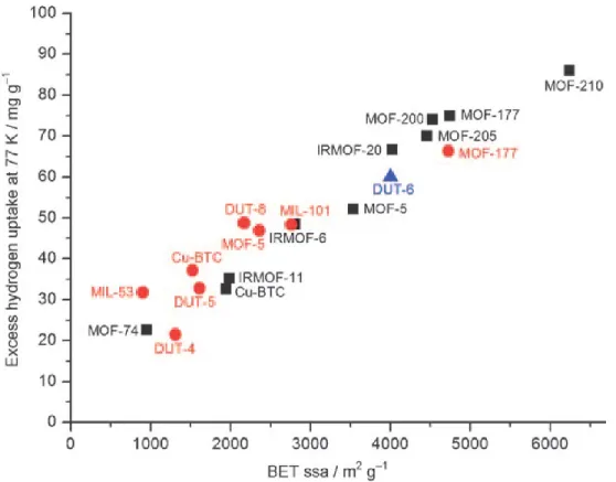
Figure 1.23. Excess hydrogen uptake at 77 K versus BET specific surface area (BET ssa) for various high-porosity MOFs. The symbols denote measurements conducted by different research groups (circles: at 20 bar by Hirscher et al.[193] triangles: at 60 bar by Kaskel et al.[194]; squares: saturation values by Yaghi et al.).[195] ... 41
Figure 1.24. MOF-117 structure and comparison of the volumetric CO2 capacity of crystalline MOF-177 relative to zeolite 13X pellets, MAXSORB carbon powder, and pressurized CO2.[200] ... 42
Figure 1.26. A portion of the structure of the sodalite-type framework of Cu-BTTri (1)
showing surface functionalization of a coordinatively unsaturated Cu(II) site with
ethylenediamine, followed by attack of an amino group on CO2 . ... 44
Figure 1.27. Detail of Pd-MOF, showing the 4-membered and the two 6-membered rings. 3D arrangement of the sodalite cages in sodalite-type frameworks. ... 46
Figure 1.28. (a) Basic building block of Cu(2-pymo)2 and (b) Diagram of the asymmetric unit of the Co(PhIM)2 framework ... 47
Figure 1.29. Transformation of ZIF-90 (A) by Reduction with NaBH4, and reaction with ethanolamine to give ZIF-91 (B) and ZIF-92 (C) [213] ... 49
Figure 1.30. (a) Eight-coordinate molecular building block that could be represented as a tetrahedral building unit, (b) [H2TMPyP]4+ porphyrin, (c) crystal structure of rho-ZMOF (left), hydrogen atoms omitted for clarity, and schematic presentation of [H2TMPyP]4+ porphyrin ring enclosed in rho-ZMOF R-cage (right, drawn to scale) [217] ... 51
Figure 2.1. Methods studied for the synthesis of nanozeolites ... 61
Figure 2.2. Scheme of the autoclave: (1) a cylindrical stainless steel vessel, (2) a Teflon cylindrical beaker, (3) a flat Teflon cover for closing the Teflon beaker, (4) a flat stainless steel cover which was tightened up to part (1) by six screws.[3] ... 63
Figure 2.3. The excitation process ... 69
Figure 2.4. Electronic energy levels and transitions. ... 69
Figure 2.5. Principle of EDX spectroscopy ... 71
Figure 2.6. Diffraction of X-ray beams on a crystal lattice ... 72
Figure 2.7. Types of sorption isotherms.[18] ... 75
Figure 2.8. t-plot method. ... 78
Figure 3.1. XRD patterns of the as-made silylated zeolite and zeolite samples prepared from the same zeolite gel in solvent medium in the presence of organosilane and in aqueous medium in the absence of organosilane, respectively: (A) silicalite-1; (B) faujasite. ... 85
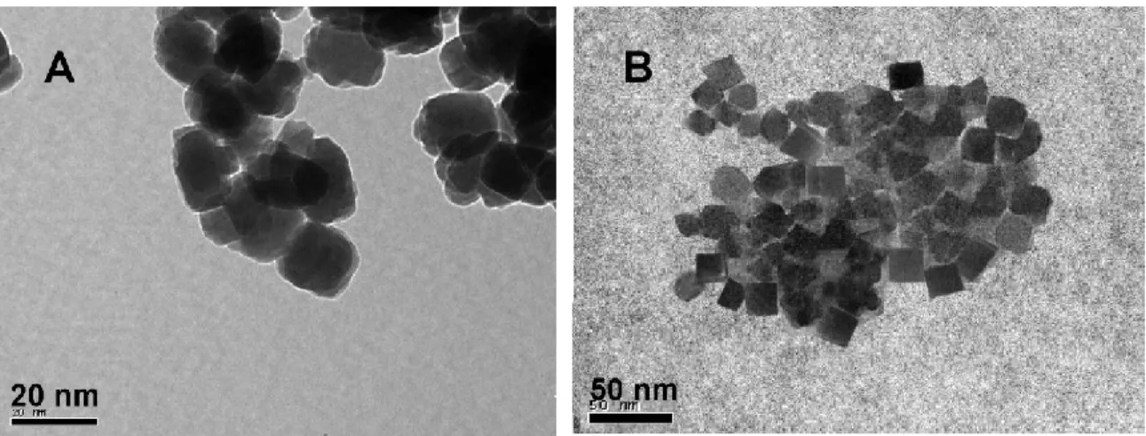
Figure 3.2. TEM images of the as-made samples: (A) silylated nanosilicalite-1, (B) silylated nanofaujasite. ... 86
Figure 4.1. Schematic representation of the two-phase synthesis method. ... 100
Figure 4.2. Schematic representation of the single-phase synthesis method. ... 103
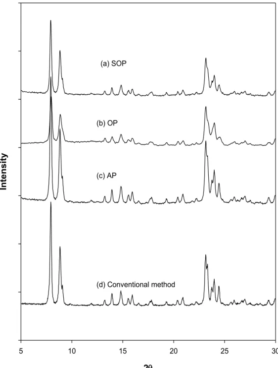
Figure 4.3. XRD patterns of the as-made silicalite-1 samples, (a) sample prepared using the conventional method in aqueous medium, (b) AP silicalite-1, (c) OP silicalite-1 using the two-phase method and (d) SOP silicalite-1 using single-phase method. ... 104
Figure 4.4. SEM micrographs of the as-made samples, (A) silylated OP silicalite-1 and (B) silylated AP silicalite-1. ... 106
Figure 4.5. TEM micrograph of the as-made SOP nanosilicalite-1 sample prepared using the single-phase method. ... 107
Figure 4.6. FTIR spectra of the silicalite-1 samples prepared using the single-phase method (A) and the conventional method (B). ... 108
Figure 4.7 29Si MAS NMR spectra of the silicalite-1 samples prepared from the same zeolite gel solution using (a) the conventional method in aqueous medium without organosilane, (b) as-made SOP nanosilicalite-1 using single-phase method in organic solvent and (c) calcined SOP nanosilicalite-1. ... 109
Figure 4.8 29Si MAS NMR spectra of the as-made silicalite-1 samples prepared from the same zeolite gel solution using the two-phase method: (a) as-made AP nanosilicalite-1 and (b) as-made OP nanosilicalite-1. ... 110
Figure 4.9. Nitrogen adsorption/desorption isotherms of the calcined samples: (A) SOP
silicalite-1, (B) OP silicalite-1 and (C) AP silicalite-1 (inset: t-plot curve). ... 112
Figure 5.1. FT-IR spectra of the prepared nanofaujasite samples: (A) FAU–TOL2D
prepared using toluene and pre-heated zeolite gel for 2 days at 90 °C, (B) FAU– FOR2D prepared using formamide and pre-heated zeolite gel for 2 days at 90 °C, (C) FAU–FOR4D prepared using formamide and pre-heated zeolite gel for 4 days at 90 °C, and (D) zeolite Y reference. ... 126
Figure 5.2. XRD patterns of nanofaujasite samples prepared: (A) FAU–TOL2D in toluene,
(B) FAU–FORM2D in formamide from the zeolite gel pre-heated at 90 °C for 2 days, (C) FAU–FORM4D in formamide from the zeolite gel pre-heated at 90 °C for 4 days, and (D) zeolite Y standard. ... 127
Figure 5.3. TEM images of (A) the sample FAU–TOL2D prepared in toluene from the
zeolite gel pre-heated at 90 °C for 2 days, (B) sample FAU–FOR2D prepared in formamide from the zeolite gel pre-heated at 90 °C for 2 days, and (C) the sample FAU–FOR4D prepared in formamide from the zeolite gel pre-heated at 90 °C for 4 days. ... 128
Figure 5.4. 29Si MAS NMR spectra of the as-made faujasite prepared in aqueous medium
in the absence of organosilane (conventional method) and silylated faujasite samples: (A) FAU–TOL4D using toluene pre-heated for 4 days, (B) FAU–FOR2D using formamide pre-heated for 2 days, (C) FAU–TOL2D using toluene pre-heated for 2 days, and (D) FAU-Standard using conventional method. ... 130
Figure 5.5. N2 adsorption desorption isotherms of (A) FAU–TOL2D prepared in toluene
from the zeolite gel pre-heated at 90 °C for 2 days, (B) FAU–FOR2D prepared in formamide from the zeolite gel pre-heated at 90 °C for 2 days, and (C) FAU-FOR4D prepared in formamide from the zeolite gel pre-heated at 90 °C for 4 days. ... 132
Figure 5.6. XRD patterns of the nanozeolite-based FCC catalyst samples prepared from the
corresponding 40, 24 and 100 nm nanozeolites: (A) FCC–TOL2D, (B) FCC–FOR2D and (C) FCC–FOR4D. ... 133
Figure 5.7. SEM image of (A) FCC–FAU–TOL2D, (B) FCC–FAU–FOR2D and (C) FCC–
FAU-FOR4D. ... 134
Figure 5.8. N2 adsorption desorption isotherms of (A) FCC–FAU–TOL2D, (B) FCC–
FAU–FOR2D and (C) FCC–FAU–FOR4D. ... 135
Figure 5.9. Relationship between conversion and catalyst-to-oil ratio of different prepared
FCC-samples. ... 137
Figure 5.10. Correlation of dry gas yield with conversion of different prepared
FCC-samples. ... 138
Figure 5.11. Correlation of LPG yield with conversion of different prepared FCC-samples.
... 139
Figure 5.12. Correlation between gasoline yield and conversion of different prepared
FCC-samples. ... 140
Figure 5.13. Relationship between gasoline selectivity and conversion of different prepared
FCC-samples. ... 141
Figure 5.15. Relation between HCO yield and conversion of different prepared
FCC-samples. ... 143
Figure 5.16. Relationship between coke yield and conversion of different prepared
FCC-samples. ... 144
Figure 6.1. XRD patterns of Fe2Ni-MIL-88B.H2O (a) and XRD simulation of the Fe3
-MIL-88B (b). ... 155
Figure 6.2. UV-Vis spectra of Fe2Ni-MIL-88B.Bp (a), Fe2Ni-MIL-88B.Pz (b), Fe2
Ni-MIL-88B.Py (c), Fe2Ni-MIL-88B.DMF (d) Fe2Ni-MIL-88B.H2O (e) and Fe3
-MIL-88B (f) ... 157
Figure 6.3. XRD patterns of Fe2Ni-MIL-88B samples, the planes of open phase are in
black, the planes of dense phase are in red and placed in boxes. Fe2Ni-MIL-88B.Bp
(a), Fe2Ni-MIL-88B.Pz (b), Fe2Ni-MIL-88B.Py (c), Fe2Ni-MIL-88B.DMF (d) and
Fe2Ni-MIL-88B.H2O (e) ... 159
Figure 6.4. N2 adsorption isotherms at 77 K (A) and pore size distributions (B) of Fe2
Ni-MIL-88B.Bp (a), Fe2Ni-MIL-88B.Pz (b), Fe2Ni-MIL-88B.Py (c), Fe2
Ni-MIL-88B.DMF (d) and Fe2Ni-MIL-88B.H2O (e). ... 162
Figure 6.5. CO2 adsorption isotherms at 273 K of Fe2Ni-MIL-88B.Bp (a), Fe2
Ni-MIL-88B.Pz (b), Fe2Ni-MIL-88B.Py (c), Fe2Ni-MIL-88B.DMF (d) and Fe2
Ni-MIL-88B.H2O (e) ... 163
Figure 7.1. UV-Vis spectra of the samples Fe3-NO3-x (A) and Fe3-Cl-x (B) prepared using
Fe(NO3)3.9H2O and FeCl3.6H2O, respectively, at different synthesis times. ... 202
Figure 7.2. UV-Vis spectra of Fe2Ni-NO3-x (A) and Fe2Ni-Cl-x (B) samples prepared
using Fe(NO3)3.9H2O and FeCl3.6H2O, respectively at different synthesis times ... 204
Figure 7.3. Transmittance FTIR spectra of the samples of Fe3-NO3-x (A) and Fe3-Cl-x (B)
at different synthesis times ... 205
Figure 7.4. Transmittance FTIR spectra of Fe2Ni-NO3-x (A) and Fe2Ni-Cl-x (B) at
different synthesis times ... 207
Figure 7.5. Raman spectra of the samples Fe3-NO3-x (A) and Fe3-Cl-x (B) at different
synthesis times ... 209
Figure 7.6. Raman spectra of Fe2Ni-NO3-x (A) and Fe2Ni-Cl-x (B) at different synthesis
times. ... 211
Figure 7.7. XRD patterns of Fe3-NO3-x (A) and Fe3-Cl-x (B) at different synthesis times.
(*) MOF-235 phase, (#): MIL-88B phase. ... 212
Figure 7.8. XRD patterns of Fe2Ni-NO3 (A) and Fe2Ni-Cl (B) at different synthesis time.
(*) MOF-235 phase, (#): MIL-88B phase ... 213
Figure 7.9. Representative HRTEM and EDS acquiring positions of Fe2Ni-Cl-12h crystal
Acknowledgement
I would like to thank the Laval Foundation for granting me the scholarship for this study.
I would like to my deep and sincere gratitude to my supervisor, Professor Trong-On Do. His wide knowledge and creative thoughts have been of great value for me. His understanding, encouraging and patience guidance have provided a good basis for the present thesis. It was a great pleasure to me to conduct this thesis under his supervision.
But it would have never come to such a happy ending if I hadn‟t met the love of my life Phuong Trinh Nguyen midway of this study. It was only with her that I found the courgage to go on with the rest of the study. She even gave up on her own academic carrier to support me. I am indebted to her love forever.
I would like to thank Professor Serge Kaliaguine for giving me the access to his laboratory where some of my experiments were carried out.
I wish to express my warm and sincere thanks to Dr. Hoang-Vinh Thang, Dr. Bousselham Echchahed and my colleagues Minh-Hao Pham and Dinh-Cao Thang who gave me invaluable thoughtful insights, advice, support, discussions and encouragements.
Special gratitude is also given to all the professors, staff and graduate students of the Department of Chemical Engineering from Laval University for their great assistance and cooperation.
Preface
This thesis documents our study in two most interesting nanoporous materials: zeolites and metal-organic framework (MOF).
As one of the most important nanoporous materials, zeolites have been widely used in catalysis, adsorption and ion exchange. Since their industrial introduction in 1954, the annual market for zeolites has grown to 1.7 million tons. The reason zeolites can “enjoy” such a great success is largely due to their interesting features: (i) high surface area, (ii) uniform pore size structure, (iii) controllable acidity/basicity, and (iv) high hydrothermostability. Inspired by zeolites, there are continuous attempts to search for other materials which can duplicate zeolites‟ features, hence their name zeotypes. These attempts have found some interesting zeotypes, however even AlPO4, which is regarded as one of
the best zeotypes, yet falls short on catalytic activity due to its neutral nature. That is why when it comes to nanoporous materials, zeolites are still the first choice for researchers. Nevertheless it is not to say that zeolites have no drawbacks. In fact due to the pore size constraints, the use of zeolites are less effective when large molecules are involved. Mesoporous materials can cope with large molecules but their amorphous nature leads to their low hydrothermostablity and low catalytic activity. So the challenge for zeolite science nowadays is to expand the application of zeolites to include large and bulky molecules.
Most of new materials can be found with inspiration from nature as in case of zeolite: with the knowledge of natural zeolites new successful methods to synthesize zeolites were proposed. Rarely a new material comes out of solely intellectual vigor without any precedent clues in nature. And the discovery of MOF was done in that unusual fashion. While zeolites are solely inorganic materials, MOFs are “ambitious” ones combining the whole two main categories of chemistry into crystalline structures: organic entities connecting to each other via inorganic metal clusters. The resulting products are huge and growing collections of MOFs with uniform nanoporous structure, extremely high surface area. With MOFs, the nanoporous material researchers can have both organic part and inorganic part to tinker with. Versatility and flexibility are the key and attractive features of MOFs, as the choice of metal cluster and organic entities is almost infinite.
Researches on MOF are explosively growing, but there are still many problems in the synthesis of MOF needed to be addressed: how the MOF forms, how to control porosity etc.
In this thesis, we look at both zeolites and MOFs and choose to solve some of the most pressing issues in these great materials. The thesis is built largely on our published or submitted papers in recent years. The first author of these papers is also the author of this thesis.
The thesis starts with an introduction in chapter 1 and then chapter 2 is an overview of the techniques used in our study. In chapter 3, pulished in Journal of the American Chemical Society 2007, 129 (13), 3810-3811, we suggest an approach to overcome the pore size limit of zeolites: reducing zeolite crystal size from microns down to tens of nanometers thus gaining more exposure of active sites to large molecules. Synthesis of nanozeolites is not an easy task, without protection nanozeolites tend to aggregate or dissolve to form large and stable crystals. We devise a new method to obtain highly uniform nanozeolites with the hydrophobic surface and controlled crystal size. The main distinction in our approaches is that an organic solvent is used as a medium for the crystallization instead of water. The zeolite precursors (nanoslabs) are functionalized with organic silane groups thus become hydrophobic and able to be well dispersed in the organic solvent. Because the crystallization occurs in the organic phase and the zeolite precursors are protected by functional groups. The aggregation can be avoided, hence, resulting in small and uniform nanozeolites with the hydrophobic external surface. Chapter 4, published in Microporous and Mesoporous Materials 2009, 120 (3), 310-316, pushes forward our new method of synthesis of nanozeolites. Attention was put onto the organic solvent. We found that depending on the amount of solvent one can have a single phase or two phase system. The results revealed that the single-phase method allows producing uniform/small nanosilicalite-1, whereas the two-phase one can bring two separate products: nanosized and microsized zeolite crystals in organic phase and in aqueous phase, respectively. Chapter 5, published in Applied Catalysis A: General 2010, 382 (2), 231-239, is our ultimate catalytic test of our nanozeolite. A series of FCC catalyst containing our nanozeolites with different sizes were prepared and tested on the gasoil cracking. The catalytic test results confirmed
our anticipation: the nanozeolites exhibit higher activity, this is due to higher external surface area and higher number of active sites available.
Chapter 6 and 7 are dedicated to MOF. In chapter 6, Published in Dalton Transactions 2013, 42 (2), 550-557, we take on one of the well-known MOFs: MIL-88B. MIL-88B is best known for its structural breathing effect upon adsorption. That is, upon interaction with various solvent molecules, the framework of MIL-88B can “swell” up and down greatly and reversibly without breaking structure. However, MIL-88B is not actually porous since solvent molecules are needed to pack its pores to sustain its swelling, when solvent is removed, the structure shrinks and its pores are blocked by the charge balancing anions. To overcome these drawbacks, the original MIL-88B was modified rationally. Neutral mixed metal cluster was used instead of the single metal cluster which requires compensating anion. Thus the anion blockage issue is avoided, the new MIL-88B is genuinely porous upon removal of solvent. Next, taking advantage of the breathing effect, we use rigid terminal ligands as “pillars” to sustain the structure. Now there is no need of solvent molecules and the swelling degree of the structure will be determined by the size of the terminal ligand. This rational approach has allowed us to control the porosity of MIL-88B at three distinct levels in terms of surface area and pore size. Chapter 7, which was submmited to CrystEngComm, continues our adventure with MIL-88B structure, we will delve into very essential problems in the synthesis of MOFs: why just a seemingly trivial substitution of iron chloride with iron nitrate results in a complete failure in the synthesis; and how the phase competition wears on to finalize the desired products. It was amazing to us that we could answer these problems with the knowledge coming from zeolite science. I propose the established mechanisms of the synthesis of zeolites are very helpful to understand the surprising mechanism by which chroride ion promotes the formation of MIL-88B structure. Alike zeolites, the synthesis of MIL-88B starts with the formation of a kinetically favored phase, and then if the synthesis time suffices, the thermokinetically stable phase will come out.
Finally chapter 8 will concluded our thesis with some additional recommendations. Bellow is the list of publications of which the contents are used in this thesis.
1. G.T. Vuong and T.O. Do, A new route for the synthesis of uniform nanozeolites with hydrophobic external surface in organic solvent medium. Journal of the American Chemical Society, 2007. 129(13): p. 3810-3811.
2. G.T. Vuong and T.O. Do, Synthesis of silylated nanozeolites in the presence of organic phase: Two-phase and single-phase methods. Microporous and Mesoporous Materials, 2009. 120(3): p. 310-316.
3. G.T. Vuong., V.T. Hoang, D.T. Nguyen, and T.O. Do, Synthesis of nanozeolites and nanozeolite-based FCC catalysts, and their catalytic activity in gas oil cracking reaction. Applied Catalysis A: General, 2010. 382(2): p. 231-239.
4. G.T. Vuong, M.H. Pham, and T.O. Do, Synthesis and Engineering Porosity of mixed metal Fe2Ni- MIL-88B Metal-Organic Framework. Dalton Transactions,
2013, 42, 550-557.
5. G.T. Vuong, M.H. Pham, and T.O. Do, Direct Synthesis and Mechanism for the Formation of Mixed Metal Fe2Ni-MIL-88B. CrystatEngComm, submitted, 2013.
Chapter 1. Introduction
1.1. Zeolite
1.1.1. Background
Zeolites (Greek, zein,"to boil", lithos, "a stone") are aluminosilicates that have well-defined porous structures. The term was originally coined in the 18th century by a Swedish mineralogist named Axel Fredrik Cronstedt who observed, upon rapidly heating a natural mineral that the stones began to dance about as the water evaporated. Using the Greek words which mean "stone that boils", he called this material as zeolite.[1]
Strictly speaking, zeolites are defined as crystalline microporous aluminosilicates with pore structures consisting of sharing TO4 tetrahedra, where T is Si or Al. Zeolites can
be described with the following empirical formula:[2]
Mn+1/n . AlO2- . x SiO2 . yH2O
Where M – counter ion
n – counter ion valence x – silicon/aluminum ratio y – content of hydrate water
Owing to the well-defined pore structure, zeolites are also known as "molecular sieves". The term molecular sieve refers to a particular property of these materials, i.e., the ability to selectively adsorb molecules based primarily on a size exclusion process. This is due to a very regular pore structure of molecular dimensions. The maximum size of the molecular or ionic species that can enter the pores of a zeolite is controlled by the diameter of the pore channels.
1.1.2. Structure
The flexibility of the zeolite Si-O-Si bond explains the fact that about 200 structures have been determined. Indeed, there is little energetic difference (10-12 kJ/mol) between these remarkable porous silicates and higher density phases such as quartz. More than 150 zeolite types have been synthesized and 48 naturally occurring zeolites are known.[3]
The structure commission of the International Zeolite Association (IZA) provides up to date classification by framework type. Each framework is assigned a three-letter code, recognized by the IUPAC Commission on Zeolite Nomenclature.[3] According to the IZA structure commission, zeolite frameworks can be thought to consist of finite or infinite (i.e., chain- or layer-like) component units. The primary building units are single TO4 tetrahedra.
The finite units which have been found to occur in tetrahedral frameworks are shown in Figure 1.1. These secondary building units (SBU), which contain up to 16 T-atoms, are derived assumption that the entire framework is made up of one type of SBU only. A unit cell always contains an integral number of SBUs. In some instances, combinations of SBUs have been encountered. However, it should be noted that the SBUs are only theoretical topological building units and should not be considered to be or equated with species that may be in the solution/gel during the crystallization of a zeolitic material.[3]
Zeolites can be also classified on grounds of their pore openings and the dimensionality of their channels. Thus, one distinguishes small pore zeolites (eight-membered-ring pores), medium pore zeolites formed by ten-membered rings, large pore zeolites with twelve-membered-ring pores and extra-large pore zeolite category. This classification simplifies comparisons in terms of adsorptive, molecular sieving and catalytic properties.
Figure 1.1. Secondary building units and their symbols. Number in parenthesis indicates
frequency of occurrence
Two important and industrially relevant structures, MFI and FAU are depicted in Figure 1.2. The channels in the MFI structure are formed by 5-1 building units linked
together. These building units render a framework of zigzag 10-membered ring channel (5.1 x 5.5 Å) and intersecting straight 10-membered ring channels (5.3 x 5.6 Å).
(a)
(b)
Figure 1.2. (a) MFI and (b) FAU structures
The FAU structure (structure of zeolite Y) is made up of 6-6 SBUs. In addition, it is possible to consider the sodalite cage, a truncated octahedron that has eight hexagonal and six square faces, as basic structure of zeolite Y. The FAU structure is formed when half of the octahedral faces are joined together to form hexagonal prisms. The spherical internal
cavity generated when eight sodalite cages are joined is called the -cage (or supercage) and is about 13 Å in diameter. Entry into the spherical -cage can occur through four identical openings that are 7.4 Å wide. The dimensions of zeolite Y allow reasonably large molecules to penetrate the internal pores, since compounds may extend through a prism into two connecting -cages.
1.1.3. General Properties of Zeolites
Figure 1.3. Inter-conversion of Brönsted and Lewis acid sites
As mentioned above, the presence of Al in the structure of zeolites results in the formation of anion sites within the framework. Charge neutralization may occur by either protonation or by interaction with a metal cation or a hydronium ion. Thus, both Brönsted and Lewis acidities may be present within the zeolite framework. The protonation of the Al-O-Si oxygen center can result in Brönsted acidity in the zeolites structure. Lewis acidity is typically related to the compensating metal ions and defects in the aluminosilicate framework. Brönsted acid sites in zeolites can change into Lewis acid sites through dehydroxylation on heating.[4]
Although zeolites are usually considered acid catalysts, cation substitution with Rb and Cs, as well as metal doping, creates a basic zeolite.[5] The presence of heavy metal cations is believed to increase the negative charge on the aluminum center, which is transferred to the adjacent oxygen atom, creating a basic site.[6]
The hydrophobicity is an important characteristic of zeolites since it can have a profound influence on their chemical reactivity. Zeolites containing charges are normally hydrophilic materials that, depending on the framework Si/Al ratio, can be more or less selective adsorbents for polar or nonpolar molecules. However, silicalite-1 which is a pure silica zeolite is a highly hydrophobic material. In contrast, FAU zeolite with the Si/A1 ratio between 2 and 5 is a highly hydrophilic absorbent. It is then clear that the polarity of a given zeolite could be controlled by controlling the Si/Al ratio by direct synthesis or by postsynthesis treatments, and this, together with appropriate control of the number of silanol groups by synthesis or postsynthesis treatments, should make it possible to prepare zeolite catalysts within a wide range of surface polarities.[7]
1.1.4. Applications
Since their successful introduction as commercial molecular sieves in 1954, synthetic zeolites have grown to an estimate $1.6-1.7 billion industry of which detergents represent the largest volume.[8] LTA-type zeolites have been used to substitute phosphate compounds in the water softening process in laundry. However, the largest market value for zeolites is in refinery catalysis. FCC (Fluid Catalytic Cracking) catalysts account for more than 95% of zeolite catalyst consumption and consist of various forms of zeolite Y. MFI-type zeolites are the second most used catalyst, primarily because they are added to FCC catalysts for octane number enhancement. Zeolites are also employed in the drying and purification of natural gas, separation of paraffins and desulfurization processes. Despite being in a relatively early stage of development, zeolites are also used in fine chemicals production such as oxidation and acylation.[8]
Zeolite science appears to be a mature science and is still a very dynamic field. Discoveries of new zeolites continuously open new areas of development. New trends at the beginning of this century include environmental applications such as De-NOx catalysis
and hydrocarbon storage in vehicles powered with diesel or gasoline engines, and biopharmaceutical applications. Zeolites can also be used in the nuclear industry for radioactive waste storage. Applications of zeolite material science still play an important role in many areas of technology.
1.2. Nanozeolites
1.2.1. Background
Nanozeolites are a type of zeolites which have the particle distribution and sizes of less than 200 nm.[9] Compared to “ordinary” zeolites of which the particle diameters are of micrometer order, nanozeolites represent very small particle size, the narrowness of their particle size distributions (often monodisperse) and especially, the fact that they are composed of discrete particles (single crystal) rather than aggregates.
One of the advantages of nanozeolites is their higher external surface area. The external surface is of vital important in numerous processes, including adsorption and catalysis. For example, in the fluidized catalytic cracking (FCC) process, the commercial catalysts are manufactured by dispersion of 1 micron FAU and MFI zeolites in an amorphous alumina-silica matrix. For cracking to occur, gasoil molecules must pass through the matrix and reach the surface of the zeolite crystals. The molecules then diffuse through the micropores of zeolites until they reach an active site. Due to the zeolite structure, molecules larger than 7.4 Å cannot reach active sites located inside the zeolites. This problem can be solved by replacing the micrometer-sized zeolites with the corresponding nanozeolites. The substitution could lead to the decrease in the diffusional resistance and the increase in the external surface area, hence raising the number of active sites available for large molecules.[10-12] Zeolite particles in the 10-100 nm range can bring in new applications of zeolites. The huge surface areas of the nanosized materials dictate that many of the atoms are on the surface, thus allowing good “atom economy” in surface-gas and surface-liquid reactions. Figure 1.4 illustrates the calculated numbers of atoms on spherical solid nanoparticles (iron) that are surface or bulk (interior) atoms. The ratio of atoms available on the surface increases as the crystal size decreases. A 20 nm particle has about 10% atoms present on the surface. This feature demonstrates that it is necessary to be very small in order to benefit from the atom economy desired.[13]
Figure 1.4. Calculated surface to bulk atom ratios for spherical nanocrystals[13]
Besides the improvement on the external surface areas, nanozeolites have been found to be excellent “building blocks” for constructing structured materials.[14] Hierarchical porous materials with controlled porosity microstructure are of great interest for catalysis and separation applications.[15-17] These porous structures can be fabricated by templated self-assembly of silicalite nanocrystals (nanosilicalite-1) and the structures so obtained include long zeolite fibers, micro-patterned zeolite films and micro-macroporous zeolite structures. The use of preformed zeolite nanocrystals for preparation of supported zeolite films and membranes is one of major applications of nanozeolites. The small size of nanozeolites offers high homogeneity and intactness of the zeolite layer and reduces the number of defects in the film, such as crack and pinholes.
1.2.2. Synthesis
1.2.2.1. Principles
A typical synthesis of nanozeolites using this method can be described as follows (Figure 1.5):
- Amorphous reactants containing silica and alumina are mixed together with a structure directing agent (SDA) source, usually in a basic (high pH) medium, resulting in a clear solution.
- The aqueous reaction mixture is heated, often (for reaction temperatures around 100 °C) in a sealed autoclave.
- For some time after raising to synthesis temperature, the reactants remain amorphous.
- After the above “induction period”, crystalline zeolite product can be detected. - Gradually, essentially all amorphous material is replaced by an approximately equal mass of zeolite crystals (which are recovered by filtration, washing and drying).
Figure 1.5. Synthesis of nanozeolites from clear solutions [18]
It is clear that a substantial understanding of the mechanism of the formation of zeolite is necessary for the synthesis of nanozeolite. However, the study on the formation of zeolites, although dates back to its earliest days,[2] has not reached its conclusion yet.[18-20] The formation of zeolite is still a developing subject which receives a lot of interest and
its study would not only benefit the zeolite science but also contribute to the understanding of the crystallization and growth of materials. The difficulties in the study of zeolite synthesis originate from its inherent synthesis conditions which involve high temperature and closed system. Hence in situ studies often require sophisticated equipment and setup. However, thanks to the application of new characterization techniques and the rapid development in computation chemistry in the last two decades, some significant discoveries have been found, giving us a better picture of zeolite formation mechanism.[21, 22]
Figure 1.6. Two pathways of zeolite formation
Unlike the crystallization of common solid materials which often involves only two distinct phases, the liquid phase and the solid phase,[23] the crystallization of zeolite implicates three phases: liquid phase, amorphous phase (or gel) and crystalline phase of
Aluminosilica gel
Zeolite
zeolite.[2] And it is the determination of the role of the amorphous phase that is the main issue in the study of the crystallization of zeolite.[18, 19] Based on the role of the amorphous phase there are two possible pathways in zeolite formation (Figure 1.6): (i) the solid pathway in which the amorphous phase is a precursor to zeolite, the transformation to zeolite taking place inside the amorphous phase via structure rearrangement; and (ii) the solution pathway in which the amorphous phase is merely a nutrient source for crystal growth by its dissolution to release active aluminosilicate monomer to the solution.
The solid pathway was suggested by Flanigen and Breck as early as 1960[2, 24, 25]. However subsequent studies on synthesis of zeolite A by Kerr and Zhdanov [19, 26, 27] in the next two decades favored the solution pathway. By the end of 1980s the solution pathway had been accepted, the nature of gel had very little impact on the final zeolite structure. The new clear solution synthesis of zeolite and the application of advanced characterization methods such as NMR and TEM in 1990s saw a numerous reports emphasizing the role of the intermediate amorphous phase. The clear solution synthesis method utilizes a clear solution of starting materials, hence facilitating the feasibility of in situ techniques, allowing better imaging of the nucleation.
For example, in the crystallization of silicalite-1, an all-silica and hydrophobic zeolite, it was revealed by de Moor et al[28] that hydrophobic silicates and structure directing agents (SDA) are assembled by hydrophobic interaction, which results in the formation of primary units (ca. 2.8 nm) in the solution prior to nucleation. Subsequently, the nucleation occurs via aggregation of primary units. The primary units were also incorporated directly into the crystalline phase during crystal growth. As the result, nucleation and subsequent crystal growth mechanisms are described by a cluster aggregation scheme (Figure 1.7). Further study was carried out by Jacobs et al.[29-33]. The silica species in an aged clear sol (which crystallizes silicalite upon heating) were extracted. The resulting powder was characterized by a wide variety of methods leading to the identification of constituent "nanoslabs" having dimensions 1.3 × 4.0 × 4.0 nm and having the MFI structure with nine intersections per particle, each constituent unit containing a TPA cation (Figure 1.8a). Aggregation of precursor units leads to larger particles measuring up to 15.6 × 8 × 8 nm and eventually to the crystalline colloidal MFI-type
material which forms the final product of the synthesis (Figure 1.8b). Hence, the authors proposed that the formation of the final silicalite-1 crystals was resulted from stacking the nanoslabs.
Figure 1.7. A scheme for the crystallization mechanism of silicalite-1[28]
Figure 1.8. The "nanoslab" hypothesis: (a) the precursor unit containing one TPA cation
and (b) schematic representation of nanoslab formation by aggregation of precursor units, as determined by XRS and GPC [32]
Figure 1.9. Nucleation and growth model of zeolite A and zeolite Y as represented by
In the crystallization of hydrophilic zeolites (low Si/Al zeolites) using clear solution method, the presence of nanosized amorphous gel particles in the pre-crystallized solution was also found.[34, 35] From the TEM observations, Mintova et al[34, 35] revealed that, these amorphous gel particles have different sizes, depending on the starting materials and the zeolite structure. The particles in the synthesis of nanozeolite A was about 5 nm whereas, those in the synthesis of nanozeolite Y was 25-35 nm. The authors proposed that the mechanism involved the aggregation of these particles (Figure 1.9).
The nucleation and growth of zeolite can be slowed down by lowering synthesis temperature thus allowing detailed observation. In a synthesis of silicalite-1 at room temperature that lasted over a year by Tsapatsis et al and other groups, the evolution of the intermediate gel from the starting clear solution was well documented.[36] The authors found that 5 – 10 nm nanoparticle gels, although appearing at early stages[37], are subject to slow structure rearrangement steps before reaching a critical precursor state that allows their aggregation to form zeolite nanoparticle (Figure 1.10). Model calculations based on the proposed mechanism are in good agreement with observation data.[38, 39]
Figure 1.10. Schematic illustration of the mechanism proposed for nanoparticle evolution
and crystal growth by aggregation.
These studies using clear solution synthesis hence emphasize the important role of the intermediate amorphous phase, implying the preference of the solid pathway. However, even in the clear solution synthesis, evidence for the solution pathway was also found.[40-42]. In the synthesis of zeolite A from clear solution, Bronić et al[42] found that the zeolite
formation is similar to the synthesis involving heterogeneous aluminosilicate gel, namely by (i) precipitation of an amorphous aluminosilicate gel precursor, (ii) formation of the particles of quasi-crystalline phase (nuclei) inside the gel matrix, (iii) „„releasing‟‟ of the nuclei from the gel matrix during its dissolution (autocatalytic nucleation) and (iv) growth of the nuclei (crystals) from the liquid phase. The remark for the clear solution synthesis is the need of high temperature (60 oC) to induce the formation of the gel while in the conventional synthesis, the gel comes readily at ambient temperature.
In summary, the two pathways: solution and solid ones are likely the two extremes of the formation of zeolite. Indeed, the formation of zeolite would always involve the cooperation of these both pathways, however, in certain conditions that one pathway will dominate over the other one. The conventional synthesis of micron-sized zeolite in which the amorphous phase forms fast at large quantity would favor the solution pathway while the clear solution synthesis would prefer the solid pathway.
Generally in the synthesis of nanoparticle materials, the crucial step is to intercept the crystal growth of the particle right after the end of the nucleation stage, thus allowing the control of the desired particle size and shape. For nanozeolite synthesis, the dominate formation pathways are very important because it is the factor to determine whether it is possible to effectively intercept the growth process. By its nature due to the presence of large gel phase in the conventional synthesis, there is no clear separation between the nucleation and the growth, in fact both processes wear on in parallel. It is possible to control the growth process in this case but the undesired impact is that the nucleation is affected also. Keep in mind that the formation of zeolite is very sensitive to the nucleation step, the interception of zeolite growth would even prevent the formation of zeolite, yielding amorphous products. In contrast the clear solution synthesis allows separated nucleation and growth, hence the control of the growth process would be possible without disturbing the nucleation process. A number of nanozeolites with different structures have been synthesized such as FAU, MFI, LTA, MOR… Most of them were prepared using clear solutions or gels, however, other methods such as confined space synthesis and synthesis using growth inhibitor have been found to be useful to synthesize these materials.
1.2.2.2. Synthesis from clear solutions
The synthesis of nanozeolites from clear solutions was first discovered by Shoeman et al[43] and Verduijn.[44] Since then this method has been widely used in the synthesis of nanozeolites (Table 1.1).
Table 1.1. Molecular sieve types synthesized in nanosized form, synthesis conditions, and
crystal size[9]
Type Molar composition of the clear synthesis solution Temp, oC size range, Crystal
nm
Ref AEI 1Al2O3:3.16P2O5:3.16(TEA)2O:186H2O 100,150,170 120-240 [45]
AEL 1.6i-Pr2NH:1.3-1.73P2O5:1.1Al2O3:35/70H2O:0/0.8-1.2HF 160,200 100-800 [46]
AFI 0.7-1.1(TEA)2O:0.6-1.0Al2O3:1.1P2O5:50H2O 160, 150-160(mw) 50-300 [47, 48]
AFI 1(TEA)2O:1Al2O3:1.32P2O5:110H2O 90,110,160(mw) 80-600 [49]
BEA Al2O3:16-400SiO2:5.16-105(TEA)2O:240-6400H2O 140 10-200 [50]
BEA 0.48Na2O:9TEAOH:0.25Al2O3:25SiO2:295H2O 100 60 [51, 52]
BEA SiO2:0.2(TEA)2O:11.8H2O 100 100 [53]
FAU 5.5Na2O:1.0Al2O3:4.0SiO2:190H2O 60 20-100 [54]
FAU
2.46(TMA)2O:0.04Na2O:Al2O3:3.4SiO2:370H2O
1.576(TMA)2O:0.044Na2O:Al2O3:3.62SiO2:246H2O
100
100
[55]
FAU 3.4SiO2:0.83-1.7Al2O3:2.3(TMA)2O:0.1NaCl:300H2O 100 80 [56]
FAU 4Na2O:0.2Al2O3:1.0SiO2:200H2O 25 100-300 [56]
FAU 1.00Al2O3:4.35SiO2:1.40-3.13(TMA)2O(2OH-
):0-2.40(TMA)2O(2Br-): 0.048Na2O:249.00H2O 100 32-120 [57]
FAU 2.46(TMA)2
O:0.032-0.43Na2O:1.0Al2O3:3.40SiO2:370H2O:13.6EtOH
100,130,
100+130 75-137 [58, 59] FAU 5.5 Na2O:Al2O3:10 SiO2:180 H2O:x NaCl 100 80 - 200 [60]
GIS 1Al2O3:4.17SiO2:2.39(TMA)2O:253H2O 100 30-50 [61]
LTA
2.0-2.3(TMA)2O:0.2-0.5Na2O:Al2O3:3.4SiO2:370H2O
1.2(TMA)2O:0.42Na2O:Al2O3:3.62SiO2:246H2O
100
230-240
[43, 55]
LTA 1.12-3.6SiO2:1.0Al2O3:1.5-7(TMA)2
O:0.007-0.28NaCl:276-500H2O 100
50+130-900 [34, 62] LTA 6.1-15.8SiO2:Al2O3:17Na2O:0.9-6.5(TMA)2O:389H2O:3iPrO2 80 50-100 [63]
LTA 0.3Na2O:11.25SiO2:1.8Al2O3:13.4(TMA)2O:700H2O 22 40-80 [35]
LTA 0.22Na2O:5.0SiO2:Al2O3:8.0(TMA)2O:400H2O 63 130 [64]
LTL 10-12.5K2O:1.0Al2O3:16-40SiO2:250-450H2O 140-190 30-70 [48]
LTL 10K2O:1Al2O3:20SiO2:400H2O 175 50-60 [65]
LTL 8.0K2O:Al2O3:20SiO2:200H2O 72.5,82.5,92.5 30-75 [66]
LTL 0.005BaO:0.25K2O:0.08Al2O3:1.0SiO2:15H2O 170 140 [67]
MEL 0.55Na2O:1.26(TBA)2O:10SiO2:150H2O 67.5,90 50-200 [68]
MEL SiO2:0.3TBAOH:4.0EtOH:18H2O 22+100 90 [69]
MFI 5-9TPAOH:0-0.3Na2O:25SiO2:0-0.25Al2O3:480-1500H2O 98 130-230 [70]
MFI 1Al2O3:60SiO2:21.4TPAOH:650H2O 170 10-100 [71]
MFI 9TPAOH:0.16Na2O:1Al2O3:50Si:300-495H2O:0/100EtOH 165 15-60 [72]
MFI Al2O3:60SiO2:11TPAOH:900H2O 70,90 10-20 [73]
MFI 0/0.53Na2O:0.62-1.52(TPA)2O:10SiO2:60/143H2O 50,60, 80 25-80 [44]
MFI 9TPAOH:0/0.1Na2O:25SiO2:480/1500H2O:100EtOH 98 95-180 [74]
MFI 0.01-0.443TPAOH:20-80H2O:TEOS 115 >90 [75, 76]
MFI 9TPAOH:25SiO2:480H2O:100EtOH
60,80,60+ 100,
80+100 60-80
[77]
MFI 3-13TPAOH:25SiO2:480H2O:100EtOH 95 100 [78]
MFI 3.0/4.5/9.0TPAOH:16NaOH:50SiO2:495/2000H2O:100EtOH 60-98,165 20-1000 [79]
MFI 0.27Na2O:5TPAOH:25SiO2:420H2O 22+230 130-260 [80]
MFI 9TPAOH:25SiO2:0.13Na2O:595H2O:100EtOH 60,100
60- 170,100-300 [81] MFI 9TPAOH:25SiO2:0.13Na2O:595H2O:100EtOH 22+60,22+100 55- 160,70-230 [82]
MFI 9TPAOH:0.25TiO2:25SiO2:404H2O:100EtOH 100 85 [83]
MFI 0.36TPAOH:0.06TiO2:1.00SiO2:16.2H2O:4EtOH:0.24BuOH 22+175(mw) <100 [84]
MFI 25 SiO2:3-9TPAOH:480-1500H2O:100EtOH. 100 100 – 200 [85-87]
MFI 20SiO2 : 9TPAOH : 9500H2O 40 100 [88]
MFI 20SiO2 : 7.2TPAOH : 360H2O 92 20 - 50 [89]
MFI 25SiO2 : 9TPAOH : 400H2O 95 100 [90]
MOR 6Na2O:2Al2O3:30SiO2:780H2O+seeds 150 63 [91]
OFF 2.78(TMA)2O:0.47-0.98K2
O:0-0.5Na2O:Al2O3:9.90H2O:91H2O 85 45-60 [44, 92]
OFF 10SiO2:1.0Al2O3:110-220H2O:0.12Na2O:0.5K2
O:3-4.5(TMA)2O 100 30-250 [92, 93]
SOD 14(TMA)2O:0.85Na2O:1.0Al2O3:40SiO2:805H2O 100 37 [43]
ZSM-22 1.52(TMA)2O:0.53Li2O:0-0.08Na2O:3.4SiO2:315H2O 100 49-108 [61]
Parameters affecting the crystal size
From the perspective of crystallization theory, the crystal size is a function of the ratio between rate of nucleation and rate of growth.[23] Thus, to obtain nanozeolites, one should optimize these following conditions: (i) attaining very high nucleation rates and (ii) providing stabilization of nuclearsized entities. The first condition is controlled by many parameters such as temperature, alkalinity, aging… whereas the second one depends chiefly on the role of SDAs. Here is a brief review of these parameters.
- Temperature: a low crystallization temperature (80 – 100oC) is often applied. This is because temperature raises growth rate more than nucleation rates. However, it should be
noted that a too low temperature usually results in poor crystallinity, low efficiency, and longer crystallization time.
- Aging: the aging of the synthesis mixture at room temperature has significant influence on the nucleation rates. This is due to the fact that nucleation rate is favored at room temperature, but the growth rate is negligible, and thus the nuclei prevail until the temperature is raised.
- Alkalinity: the concentration of OH- ions strongly increases the solubility of silicate species. In general, smaller zeolite crystals tend to formed at higher alkalinity.[60]
- The concentration of the clear solution strongly affects the degree of saturation of the system. At lower supersaturation, growth is favored at the expense of nucleation. Dilution of the solution can cause large crystal to form. Hence a high concentration is a desired parameter.
- The solubility of the silica source plays an important role in the synthesis of nanozeolites. Smaller crystals are formed from monomeric silicate solutions than by dissolution of colloidal silica.
- Metal cations usually facilitate the crystal growth. Hence, they should be present in the synthesis solution at low concentration. For example, it has been found that sodium is the growth-limiting nutrient in the formation of Y-type zeolite.[43, 59] The crystallizations of Y-type and A-type zeolites are very sensitive to sodium content. In some cases, a small variation in this factor results in the formation of a different crystal phase, for the synthesis of zeolites with the clear synthesis gel having molar composition of 2.46 (TMA)2O: x
Na2O: 1.0 Al2O3 : 3.40 SiO2 : 370 H2O:13.6 EtOH (0.03 < x < 0.43), the sodium
concentration of the batch is crucial for controlling which zeolite phase crystallizes. Greater Na2O/Al2O3 ratio (0.43) in the batch favors the formation of zeolite A with a higher yield of
56.5% after a shorter crystallization time. Lower Na2O/Al2O3 ratio (0.03) in the batch
produces smaller zeolite Y crystals with a lower yield of 8.1% after a longer crystallization time.
- Structure directing agent (SDA): SDAs are often quaternary of the type [R4N]+OH
-(where R is an alkyl group, typically CH3, C2H5, C3H7 or C4H9). The presence of SDA in
the synthesis solution helps assist the formation of desired zeolite structure. Furthermore, SDA is responsible to the stabilization of silicate subcolloidal particles[94] as well as the nanozeolites.[95] In the synthesis of nanosilicalite-1 using tetrapropylammonium hydroxide (TPAOH) as SDA, it was revealed[95] that, there were two different environments for the TPA+ cation: (i) TPA+ occluded in the channel intersections and (ii) TPA+ adsorbed on to the external surface of the particles. Bulky quaternary ammonium cations adsorbed on to particle surfaces provide steric stabilization, preventing aggregation upon collision. In an aqueous medium, zeolite particles will acquire a negative surface charge due to dissociation of the surface silanol groups. Such a surface charge will cause organic cations in the surrounding solution to align along the particles‟ surface, creating an electric double layer. This stabilizing barrier of bulky organic cations restricts the close approach of similar particles, such that the attractive potential between them is insufficient to cause aggregation or flocculation.
1.2.2.3. Synthesis using growth inhibitor
The synthesis of nanozeolites using growth inhibitor is in fact derived from the synthesis from clear solution. In this method, an organic additive other than SDA is introduced to inhibit the growth process, thus resulting in small zeolite crystals. The reactivity of the additive and its content in the synthesis mixture are two significant factors. The addictive should be able to adsorb on to or react with the surface of the silicate particles, thus, protects them from further aggregation. If the concentration of the additive is too high, zeolite might not be obtained since there would be not sufficiently free aluminosilicate species for the formation of zeolite structure. In contrast, if the concentration is too low, the inhibition effect might be inadequate.
Hosokawa et al[96] revealed that, a nonionic surfactant (polyoxyethylene lauryl ether, C12E6) and polyethylene glycol (PEG 600) were able to act as the growth inhibitors in the synthesis of nanosized A-type zeolites. The inhibitor was added with the synthesis mixture prior to crystallization. TEM investigation showed that the resulting zeolite A was
in the form of aggregated 30 – 40 nm particles which was nearly similar to the size of the aluminosilicate precursor species available in the synthesis gel prior to crystallization. This observation indicated that the growth of the zeolite crystals should be inhibited.
The introduction of a growth inhibitor can be postponed until viable zeolite precursors become prevalent. Thus the undesired interference of the inhibitor in the formation of precursors is avoided. This approach was developed by Naik et al[97] for preparation of nanosilicalite-1. The procedure involves: (i) prepare a clear solution that is known to produce colloidal TPA-silicalite upon extended hydrothermal reaction; (ii) subject the solution to hydrothermal condition but stop before the appearance of colloidal silicalite; (iii) protect the TPA-silicalite precursor nanoparticles with cationic surfactant (CTABr) and collect them as flocculated mass; (iv) convert the precursor/surfactant hybrid into nanocrystals via high temperature steaming. A steaming temperature of 150 oC was found enough to convert the collected precursor into nanocrystals. The obtained nanocrystals were smaller than 30 nm. However these particles are hard aggregated and can not redispersed in water.
Serrano et al[98] reported the use of organosilane as the growth inhibitor. Organosilane is a good silylating agent which has been widely used for the functionalization of zeolites. According to the author, MFI and beta zeolites were successfully synthesized, using phenylaminopropyl-trimethoxysilane (PHAPTMS). The synthesis is based on reducing the growth of zeolite crystals by silanization of the zeolitic seeds to hinder their further aggregation. Typically, the synthesis of MFI zeolite is as follows: a clear solution of TPA-aluminosilicate was produced. The precursor solution was precrystallized under reflux with stirring (100 rpm) at 90 ºC for 20 h. Then, the zeolite seeds obtained were functionalized by reaction with PHAPTMS at 90 ºC for 6 h. Finally, the resulting solution was subjected to hydrothermal treatment at 170 oC for 5 days. However, as investigated by TEM analysis, the MFI sample obtained consisted of particles of about 300 – 400 nm which were formed by aggregation of ultra small primary units of 10 nm. Having that large size, the sample was hardly considered as true nanozeolite.
1.2.2.4. Confined space synthesis
In the field of zeolite science, the term “confined space” was first used by Jabobsen et al. [99-102] in 1999 to describe a novel method for zeolites synthesis which allows preparation of nanosized zeolites crystals with a controlled crystal size distribution. The principle of confined-space synthesis is to synthesize the zeolite inside the mesoporous of an inert matrix. The maximum crystal size is limited by the diameter of the mesopores as shown in Figure 1.11
The zeolite gel is introduced into the mesopores of the matrix by sequential incipient wetness impregnations the matrix with the gel precursor solution. For the synthesis of ZSM-5, the carbon black was impregnated to incipient wetness with a clear solution of TPAOH, H2O, NaOH and ethanol. After aging for 3 h at room temperature, the
carbon black was subjected to hydrothermal treatment at 180 oC for 48 h in an autoclave. The product was then recovered by calcinations to remove the matrix.[99]
Figure 1.11. Schematic illustration of confined space synthesis.[101]
This method has also been applied to the synthesis of beta, X and A zeolites.[101, 102] Two carbon black matrixes were used with a pore diameter of 31.6 and 45.6 nm, respectively. Generally, the crystal size distributions of the zeolites obtained were governed
![Figure 1.9. Nucleation and growth model of zeolite A and zeolite Y as represented by TEM [34, 35]](https://thumb-eu.123doks.com/thumbv2/123doknet/5964562.147691/33.918.277.690.112.951/figure-nucleation-growth-model-zeolite-zeolite-represented-tem.webp)
![Table 1.1. Molecular sieve types synthesized in nanosized form, synthesis conditions, and crystal size[9]](https://thumb-eu.123doks.com/thumbv2/123doknet/5964562.147691/36.918.101.777.319.1079/table-molecular-sieve-synthesized-nanosized-synthesis-conditions-crystal.webp)
![Figure 1.12. Schematic representation of synthesis of template-free zeolite nanocrystals by using in situ thermoreversible polymer hydrogels.[104]](https://thumb-eu.123doks.com/thumbv2/123doknet/5964562.147691/43.918.169.793.290.635/figure-schematic-representation-synthesis-template-nanocrystals-thermoreversible-hydrogels.webp)