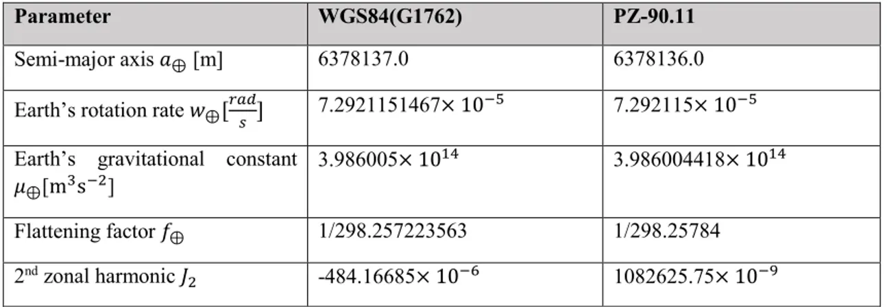
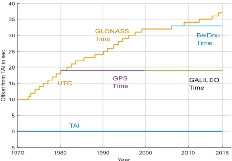
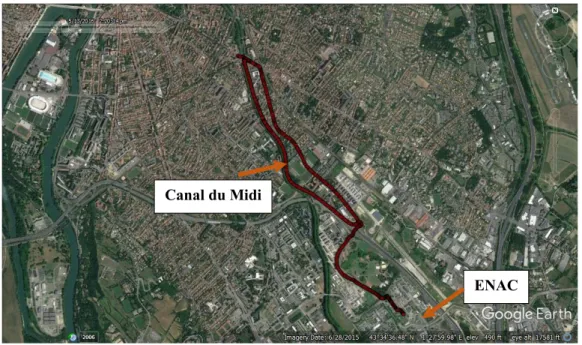
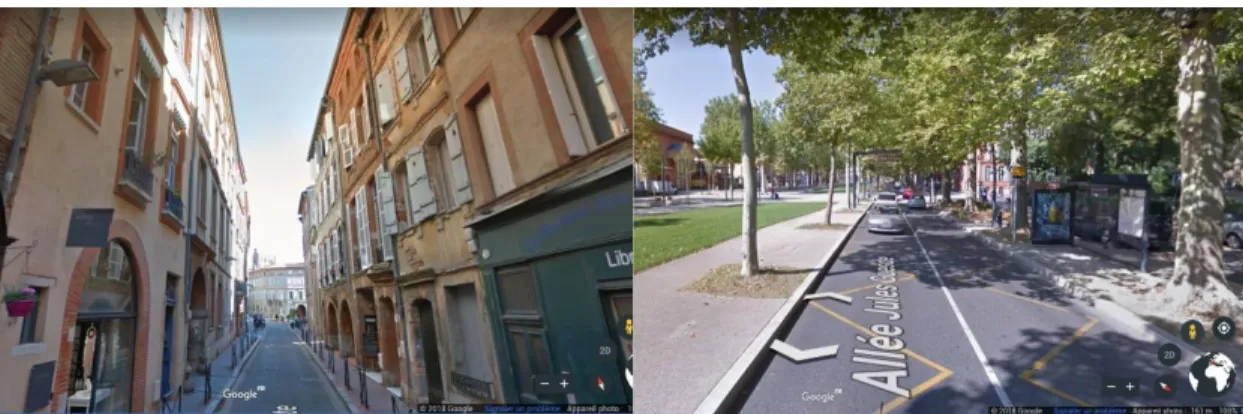
Localization Precise in Urban Area
157
0
0
Texte intégral
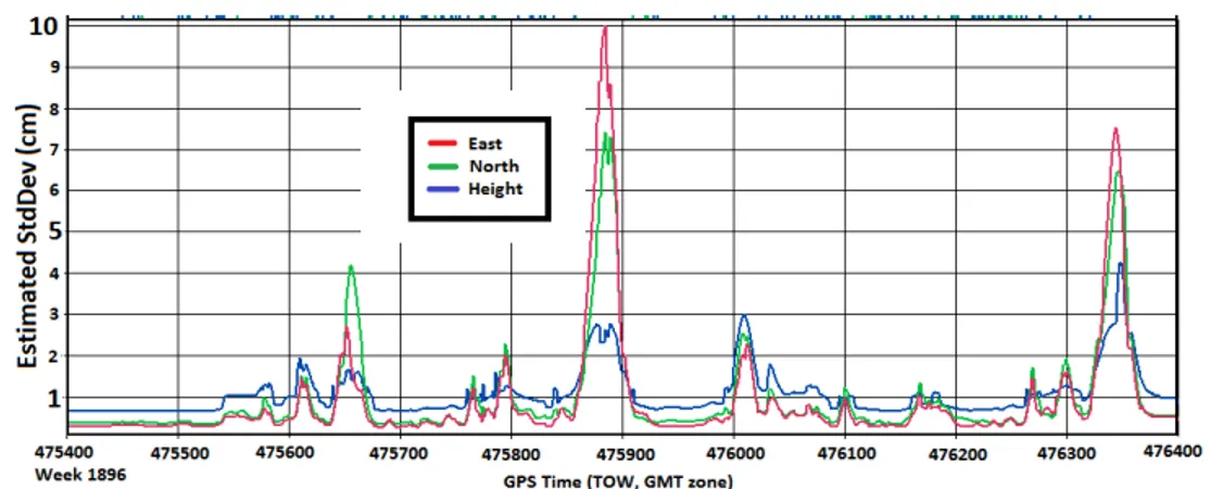
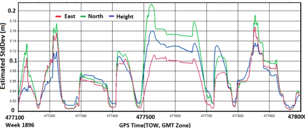
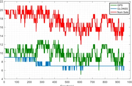
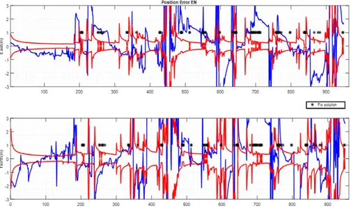
Figure
+7
Documents relatifs