CONTROLLED WETTING IN MULTIPHASE POLYMER BLENDS WITH POLYLACTIDE: MORPHOLOGY AND PERFORMANCE
MOHAMMAD ALI ZOLALI DÉPARTEMENT DE GÉNIE CHIMIQUE ÉCOLE POLYTECHNIQUE DE MONTRÉAL
THÈSE PRÉSENTÉE EN VUE DE L’OBTENTION DU DIPLÔME DE PHILOSOPHIAE DOCTOR
(GÉNIE CHIMIQUE) DÉCEMBRE 2016
UNIVERSITÉ DE MONTRÉAL
ÉCOLE POLYTECHNIQUE DE MONTRÉAL
Cette thèse intitulée:
CONTROLLED WETTING IN MULTIPHASE POLYMER BLENDS WITH POLYLACTIDE: MORPHOLOGY AND PERFORMANCE
présentée par : ZOLALI Mohammad Ali
en vue de l’obtention du diplôme de : Philosophiae Doctor a été dûment acceptée par le jury d’examen constitué de:
M. TAVARES Jason-Robert, Ph. D., président
M. FAVIS Basil, Ph. D., membre et directeur de recherche M. VIRGILIO Nick, Ph. D., membre
DEDICATION
To Raziyeh To my parents
ACKNOWLEDGEMENTS
I would like to express my sincere thanks to my advisor, Professor Basil Favis, for his guidance throughout this research and his constant support and encouragement. I am honored to have had the opportunity to work as a Ph.D. candidate under his supervision. His accurate, practical and realistic attitude toward scientific research will certainly hold positive influences on my career and personal life.
Thanks to Prof. Jason Tavares, Prof. Nick Virgilio, and Prof. Guo-Hua Hu for taking part in my thesis committee.
The experiences which I have had with members of my research group have not only provided me with a wealth of scientific resources, but memories which have allowed me to grow as a person. I wish to thank Vahid Heshmati, Ebrahim Jalali, Jun Wang, Ata Taghizadeh, and Mehdi Pakravan for fruitful discussions.
I would like to thank friends in the Department of Chemical Engineering. I greatly value their friendship and I deeply appreciate their help.
I also would like to thank the technical and administrative staff of the Department of Chemical Engineering at Polytechnique Montréal.
Most importantly I would like to thank my family. I never could have done it without their support and encouragement. To my parents and my parents-in-law who have always supported me to continue my studies. To my sons, Parsa and Borna, for being such wonderful little people, at least most of the time. To my wife, Raziyeh, thank you for your understanding and the sacrifices that you have made during the long drawn out process. You will never know how much I appreciate all that you have done for me. This never would have become a reality without your love and support.
RESUME
Le mélange de polylactide (PLA) avec d’autres polymères est une approche viable à l’expansion dans d’autres champs d’applications. La vaste majorité de la littérature concernant les mélanges à base de PLA ce concentrent sur les mélanges binaires. Malgré tout, récemment, les mélanges de polymères multi-phases ont reçu une attention particulière dû à leur potentiel en tant que matériaux multifonctionnel haute performance. La clé pour obtenir de tels matériaux est de contrôler la morphologie des phases et de comprendre sa relation avec les propriétés. Pour les mélanges multi-phases de polymères, particulièrement un système ternaire, deux grandes catégories d’états morphologiques sont définies : le mouillage complet, qui montre un comportement de contact entre deux phases, et le mouillage partiel, où trois sont en contact l’une avec l’autre et qui vient seulement de commencer à être étudié en détail récemment. Cette dissertation fait état de la morphologie de mélanges ternaires et quaternaires à base de PLA dans le contexte des deux états de mouillage et leur relation avec les propriétés mécaniques.
Dans la première partie de cet ouvrage, nous examinons la morphologie de mélanges ternaires et quaternaires du PLA avec le poly(butylene succinate) (PBS), le poly(butylene adipate-co-terephthalate) (PBAT) et le poly(3-hydroxybutyrate-co-hydroxyvalerate) (PHBV). Les échantillons mélangés à l’état fondu ont subi un traitement thermique subséquent afin de déterminer les états thermodynamiques les plus stables de mouillage complet ou partiel. Les tensions interfaciales entre les composantes ont été mesurées à l'aide de trois techniques différentes, à savoir : la rupture du fil (BT), la rétraction des fibres ancrées (IFR), et l’approche triangle-in situ de Neumann (NT). L’imagerie FTIR est présentée comme une nouvelle méthode d'identification de phase et d'analyse de la morphologie utile pour caractériser les systèmes multi-phases de structures chimiques similaires, tels que les bio-polyesters utilisées dans ce travail. Les mélanges ternaire 33PLA/33PBS/33PBAT montrent un comportement au mouillage complet tri-continu avant et après un traitement thermique, ce qui concorde étroitement avec l'analyse de la théorie d'étalement. Le système quaternaire PLA/PBS/PBAT/PHBV montre un comportement de mouillage dépendant de la concentration. Une morphologie complètement mouillée continue des quatre phases est trouvée pour 25PLA/25PBS/25PBAT/25PHBV après mélange. Durant le traitement thermique, il y a rupture des phases de PBAT qui forment des gouttelettes à l'interface PBS/PHBV. Cependant, à 10% volumique de PBAT, des gouttelettes partiellement mouillées de PBAT à l'interface de PBS et PHBV sont observés et ils restent stables après le recuit quiescent.
Les résultats morphologiques après recuit pour le mélange quaternaire sont fortement corrélés avec les prédictions thermodynamiques basées sur les mélanges ternaires constitutifs. Ces résultats montrent que le contrôle de la composition pour le mélange des systèmes multi-phases avec de faibles tensions interfaciales peut se traduire par un changement complet du comportement d'étalement.
Dans la deuxième partie de cette recherche, nous étudions le comportement de mouillage de trois phases intermédiaires différentes en fonction de la composition et du recuit de mélanges ternaires produit à l'état fondu PLA/PHBV/PBS, PLA/PBAT/PE et PLA/PE/PBAT. Ces systèmes ont tous montrés un comportement de mouillage partiel. Une transition d’un mouillage partiel à complet est observée pour les gouttelettes partiellement humides de PHBV et PBAT dans le PLA/PHBV/PBS et PLA/PBAT/PE, tandis que les gouttelettes de PE partiellement mouillées restent stables à l'interface du PLA/PBAT même à une concentration élevée en PE de 20% et après 30 min de recuit quiescent. La tension interfaciale des différentes composantes et les angles de contact des gouttelettes partiellement mouillées, confinées à l'interface de contact, ont été examinés en détail. L'analyse thermodynamique des coefficients d'étalement prédit une faible tendance au mouillage partiel pour les gouttelettes de PHBV et de PBAT dans le PLA/PHBV/PBS et le PLA/PBAT/PE, tandis qu'un mouillage partiel fort est prévu pour les gouttelettes de PE dans le PLA/PE/PBAT. Les trois systèmes de mélange présentent une coalescence considérablement améliorée en fonction de la composition et du temps de recuit, à cause du confinement des gouttelettes à l'interface. Un modèle de ségrégation est utilisé pour expliquer les divers phénomènes de mouillage et leur dépendance à la concentration et au temps de recuit. Les résultats indiquent le potentiel évident que le confinement interfacial, la composition, et le temps de recuit dans les systèmes multiphases ayant une morphologie avec mouillage partiel, puissent se traduire par un changement complet du comportement d’étalement. Ce travail montre l'excellent potentiel pour le mouillage contrôlé et la structuration des systèmes de polymères ternaires et présente une voie vers la préparation d'une panoplie de nouvelles structures morphologiques.
Dans la troisième partie de ce travail, nous examinons l'effet d'une structure de mouillage partiel sur la compatibilisation et la trempe d'un mélange co-continu de PLA/PA11. Quatre polymères différents : le PBS, le PBAT, l’EMA et l’EMA-GMA sont examinés pour leur capacité à mouiller partiellement l'interface PLA/PA11 dans un procédé de mélange en phase fondue, grâce à l’analyse de la morphologie et des propriétés physiques. Tous les mélanges présentent une morphologie de
mouillage partiel avec une gamme d'efficacités de compatibilisation et d’effets de durcissement. L’EMA-GMA montre le meilleur effet de compatibilisation en réduisant la taille de la phase co-continue à près de la moitié de celle du mélange binaire PLA/PA11 initial, en atteingnant 5-6 µm. Une augmentation significative de la ductilité des mélanges ternaires est obtenue, l’EMA montrant la plus forte amélioration avec un allongement à la rupture de 260% par rapport à 4% pour le mélange binaire. Une augmentation substantielle de la résistance au test de choc Izod est également obtenue avec l’EMA montrant quatre fois la résistance à l'impact du mélange binaire d'origine à 73 J/m. Nous croyons que les effets combinés de la morphologie compatibilisé, une bonne adhérence interfaciale et la cavitation interfaciale percolé de gouttelettes partiellement mouillées, suivis par la rupture en cisaillement de la matrice contribuent à l'effet de durcissement observé dans les mélanges ternaires partiellement mouillés. Ces résultats suggèrent une technique intéressante qui exploite les gouttelettes partiellement mouillées afin de compatibiliser et renforcer les structures co-continues.
Enfin, nous étudions la corrélation entre une morphologie de mouillage complet et l’augmentation de la ténacité dans un mélange ternaire à base de PLA/PA11. Nous montrons que lorsque du polyéther-b-amide (PEBA) est ajouté à au mélange PLA/PA11, il se propage entièrement à l'interface et s’assemble en une couche mince à l'interface du PLA et PA11 entièrement percolés. Ceci augmente considérablement la résistance à l’impact Izod, pour atteindre 142,4 J/m, par rapport à 17,3 J/m pour le mélange de PLA/PA11. L'addition supplémentaire d'oxyde de polyéthylène (PEO), dans la phase de PLA résulte en un matériau ultra-tenace manifeste par l’augmentation spectaculaire de la résistance à l’impact Izod qui atteint 728,6 J/m. Le PEBA est un élastomère thermoplastique capable de fortes interactions interfaciales avec le PLA et le composant amide dans le copolymère a une affinité naturelle pour le PA11. Le PEO ajoutée renforce également les interactions interfaciales et la mobilité de chaîne du PLA. La ténacité à la traction et la résistance à l’impact Izod sont fortement influencés par la région critique de la composition co-continue du système binaire PLA/PA11, les mélanges au-delà de cette région de composition démontrent une mauvaise ténacité. On constate que les effets combinés de la co-continuité, d’interactions interfaciales fortes, d’une interface déformable et d’une mobilité suffisante des chaînes de PLA sont tous essentiels à la réalisation du comportement ultra tenace dans le mélange PLA/PA11. Les surfaces de fracture des tests d’impact des mélanges ont été analysées et les résultats ont révélés une cavitation significative au sein de la phase PEBA déformable. Un mode de rupture ductile par
cisaillement est observé dans les mélanges ultras tenaces qui devrait être induite par le chevauchement des contraintes dans la phase PEBA déformable, conjointement à une adhérence interfaciale appropriée. Ces résultats établissent une stratégie pour l’augmentation de la ténacité des mélanges de polymères à phases multiples, en particulier à proximité de la région de co-continuité.
ABSTRACT
Blending of polylactide (PLA) with other polymers is a viable approach to promote its broader implementation. The vast majority of the PLA-based blend literature is based on binary blends, however, recently, multiphase polymer blends have received a marked interest due to their potential in generating high performance multi-functional materials. The key in achieving such materials is to control the phase morphology and understand its relationship with properties. For multiple phase polymer blends, particularly a ternary system, two broad categories of morphological states are defined: complete wetting, which demonstrates two phase contact wetting behavior, and partial wetting, in which three phases are in contact with each other and has only begun to be examined in detail recently. This dissertation reports on the morphology of ternary and quaternary PLA-based blends in the context of the two wetting regimes and its relationship with the mechanical properties. In the first part of this work, we examine the morphology of ternary and quaternary blends of PLA with poly(butylene succinate) (PBS), poly(butylene adipate-co-terephthalate) (PBAT) and poly(3-hydroxybutyrate-co-hydroxyvalerate) (PHBV). Samples were melt blended and then annealed to determine the most stable complete or partial wetting thermodynamic states. The interfacial tensions between components were measured using three different techniques, i.e. breaking thread (BT), imbedded fiber retraction (IFR), and the in-situ Neumann triangle approach (NT). FTIR-imaging is presented as a new phase identification and morphology analysis method useful for characterizing multiphase systems of similar chemical structures such as the biopolyesters used in this work. The ternary 33PLA/33PBS/33PBAT blends demonstrate a tri-continuous complete wetting behavior before and after quiescent annealing which correlates closely with the spreading theory analysis. The quaternary PLA/PBS/PBAT/PHBV system shows a concentration dependent wetting behavior. A fully quadruple continuous completely wet morphology is found for 25PLA/25PBS/25PBAT/25PHBV after mixing where the PBAT phase breaks up and forms droplets at the PBS/PHBV interface upon quiescent annealing. However, at 10 vol.% PBAT, partially wet droplets of PBAT at the interface of PBS and PHBV are observed and they remain stable after quiescent annealing. The morphological results after annealing for the quaternary blend strongly correlate with the thermodynamic predictions based on the constituent ternary blends. These results show that composition control during the mixing of multiphase systems with low interfacial tensions can result in a complete change of spreading behavior.
In the second part of this research, we study the wetting behavior of three different intermediate phases as a function of composition and annealing in melt blended ternary PLA/PHBV/PBS, PLA/PBAT/PE and PLA/PE/PBAT systems all demonstrating partial wetting behavior. Although, partially wet PE droplets remain stable at the interface of PLA/PBAT even at a high PE concentration of 20% and after 30 min of quiescent annealing, a partial to complete wetting transition is found for both PHBV and PBAT partially wet droplets in the PLA/PHBV/PBS and PLA/PBAT/PE systems, respectively. The interfacial tension of the various components and the contact angles of the confined partially wet droplets at the interface were examined in detail. The thermodynamic analysis of the spreading coefficients predicts a weak partial wetting tendency for PHBV and PBAT droplets in PLA/PHBV/PBS and PLA/PBAT/PE, respectively, while a strong partial wetting is predicted for PE droplets in PLA/PE/PBAT. All three blend systems show significantly enhanced coalescence as a function of composition and annealing time due to the interfacial confinement of the droplets at the interface. A dewetting model is used to explain the various wetting behaviors and their dependence on concentration and annealing time. The results indicate the clear potential that interfacial confinement, composition, and annealing time in multiphase systems with partial wetting morphology can result in a complete change of spreading behavior. This work shows the excellent potential for controlled wetting and structuring in ternary polymer systems and presents a route towards the preparation of a range of new morphological structures.
In the third part of this work, we examine the effect of partial wetting structure on the compatibilization and toughening of a co-continuous PLA/PA11 blend. Four different polymers: PBS, PBAT, EMA and EMA-GMA are examined for their capacity to partially wet the PLA/PA11 interface in a melt-blending process. All the blends exhibit a partial wetting morphology with a range of compatibilization efficacies and toughening effects. EMA-GMA demonstrates the best compatibilization effect by reducing the co-continuous phase size to about half that of the original binary PLA/PA11 blend at 5-6 µm. A significant increase in the ductility of the ternary blends is achieved where EMA shows the highest enhancement with an elongation at break of 260% as compared to 4% for the binary blend. A substantial increase in the notched Izod impact strength is also obtained with EMA demonstrating four times the impact of the original binary blend at 73 J/m. The combined effects of compatibilized morphology, good interfacial adhesion and the interfacially percolated cavitation of partially wet droplets followed by shear yielding of the matrix
is believed to contribute to the toughening effect observed in the partially wet ternary blends. These results suggest an interesting technique exploiting partially wet droplets to compatibilize and toughen co-continuous structures.
Finally, we investigate the correlation between the morphology of a system demonstrating complete wetting behavior and toughening in a ternary blend based on PLA/PA11. We show that when polyether-b-amide (PEBA) is added to the PLA/PA11 blend, it completely spreads at the interface and assembles as a thin layer at the interface of a fully percolated PLA and PA11. This significantly increases the notched Izod impact strength from to 142.4 J/m as compared to 17.3 J/m for the PLA/PA11 blend. The further addition of polyethylene oxide (PEO) to the PLA phase results in an ultra-toughening effect and a dramatic increase in the Izod impact to 728.6 J/m is achieved. PEBA is a thermoplastic elastomer capable of strong interfacial interactions with PLA and the amide component in the copolymer has a natural affinity for the PA11. The added PEO is found to enhance the interfacial interactions and the chain mobility of PLA. The tensile toughness and notched Izod impact strength are significantly influenced by the critical co-continuous composition region of the PLA/PA11 binary system where the blends beyond this composition region demonstrate a poor toughness. It is found that the combined effects of co-continuity, strong interfacial interactions, a deformable interface and sufficient PLA chain mobility are all essential to achieving ultratough behavior in PLA/PA11. The impact fracture surface of the blends was analyzed and the results revealed significant cavitation within the deformable PEBA phase. A shear yielding failure mode is observed in the ultratough blends which is believed to be induced by the stress-field overlap within the deformable PEBA phase in conjunction with suitable interfacial adhesion. These results establish a strategy for the toughening of multiphase polymer blends, especially in the vicinity of the co-continuous region.
TABLE OF CONTENTS
DEDICATION ... III ACKNOWLEDGEMENTS ... IV RÉSUMÉ ... V ABSTRACT ... IX TABLE OF CONTENTS ... XII LIST OF TABLES ... XVII LIST OF SYMBOLS AND ABBREVIATIONS ... XXV LIST OF APPENDICES ... XXIX
CHAPTER 1 INTRODUCTION AND OBJECTIVES ... 1
1.1 Introduction ... 1
1.2 Objectives ... 3
CHAPTER 2 LITERATURE REVIEW ... 5
2.1 Biobased and Biodegradable plastics ... 5
2.1.1 Poly(lactide) ... 6 2.1.2 Poly(butylene adipate-co-terephthalate) ... 7 2.1.3 Poly(butylene succinate) ... 8 2.1.4 Poly(3-hydroxybutyrate-co-hydroxyvalerate) ... 8 2.1.5 Polyamide 11 ... 9 2.2 Polymer Blends ... 9 2.2.1 Miscibility ... 9 2.2.2 Interfacial Tension ... 10
2.3 Binary Polymer Blends ... 14
2.3.1 Droplet Deformation and Breakup ... 15
2.3.2 Coalescence ... 17
2.3.3 Continuity and Co-Continuity Development ... 20
2.3.4 Effect of Interfacial Tension ... 23
2.4 Multicomponent Blends ... 26
2.4.1 Wetting in Immiscible Polymer Blends ... 26
2.4.2 Thermodynamic Models ... 28
2.4.3 Ternary Polymer Blends ... 30
2.4.4 Quaternary Polymer Blends ... 38
2.5 Toughening Mechanisms ... 43
2.5.1 Crazing ... 43
2.5.2 Shear Yielding ... 44
2.5.3 Cavitation or Debonding ... 45
2.6 Mechanical Properties of Polymer Blends ... 46
2.6.1 Matrix/Dispersed Morphology ... 46
2.6.2 Co-continuous Structure ... 47
2.7 Toughening of PLA ... 48
2.7.1 Plasticization ... 48
2.7.2 Multicomponent Blends ... 49
CHAPTER 3 ORGANIZATION OF THE ARTICLES ... 52
CHAPTER 4 ARTICLE 1: PARTIAL AND COMPLETE WETTING IN ULTRA-LOW INTERFACIAL TENSION MULTIPHASE BLENDS WITH POLYLACTIDE ... 54
4.1 Abstract ... 54
4.2 Introduction ... 55
4.3 Experimental ... 58
4.3.1 Materials ... 58
4.3.2 Blend preparation and annealing ... 59
4.3.3 Rheological measurements ... 59
4.3.4 Interfacial tension measurement ... 60
4.3.5 Field emission scanning electron microscopy ... 61
4.3.6 Atomic force microscopy ... 61
4.3.7 Solvent extraction and gravimetry ... 62
4.3.8 FTIR-Imaging ... 62
4.4 Results and Discussion ... 63
4.4.2 Phase Identification ... 65
4.4.3 Ternary Systems with PLA ... 67
4.4.4 Quaternary Systems with PLA ... 71
4.5 Conclusion ... 75
4.6 Acknowledgment ... 75
4.7 References ... 76
CHAPTER 5 ARTICLE 2: PARTIAL TO COMPLETE WETTING TRANSITIONS IN IMMISCIBLE TERNARY BLENDS WITH PLA: THE INFLUENCE OF INTERFACIAL CONFINEMENT ... 82
5.1 Abstract ... 82
5.2 Introduction ... 82
5.3 Experimental ... 86
5.3.1 Materials ... 86
5.3.2 Blend Preparation and Annealing ... 86
5.3.3 Rheological Measurements ... 87
5.3.4 Interfacial Tension Measurement ... 87
5.3.5 Microtoming/Field Emission Scanning Electron Microscopy ... 88
5.3.6 Ultramicrotoming/Atomic Force Microscopy ... 88
5.3.7 Image Analysis ... 89
5.4 Results and Discussion ... 89
5.4.1 Interfacial Tensions and Spreading Coefficients ... 89
5.5 Weak Partial Wetting ... 92
5.5.1 PLA/PHBV/PBS ... 92
5.5.2 PLA/PBAT/PE ... 94
5.5.3 Strong Partial Wetting ... 96
5.5.4 Interfacial Confinement and Coalescence ... 97
5.5.5 Dewetting/Coalescence ... 101
5.5.6 Principal Transitions in Wetting Behavior ... 102
5.6 Conclusion ... 104
5.7 Acknowledgment ... 105
CHAPTER 6 ARTICLE 3: COMPATIBILIZATION AND TOUGHENING OF CO-CONTINUOUS TERNARY BLENDS VIA PARTIALLY WET DROPLETS AT THE INTERFACE 111
6.1 Abstract ... 111
6.2 INTRODUCTION ... 112
6.3 EXPERIMENTAL ... 115
6.3.1 Materials and Sample Preparation ... 115
6.3.2 Scanning Electron Microscopy ... 116
6.3.3 Atomic Force Microscopy ... 116
6.3.4 Morphology Characterization, Solvent Extraction and Gravimetry ... 117
6.3.5 Interfacial Tension Measurement ... 118
6.3.6 Differential Scanning Calorimetry ... 118
6.3.7 Mechanical tests ... 118
6.4 RESULTS AND DISCUSSION ... 119
6.4.1 Morphology... 119
6.4.2 Interfacial Interactions ... 122
6.4.3 Thermal Analysis ... 124
6.4.4 Tensile and Impact Properties ... 125
6.5 CONCLUSION ... 131
6.6 ACKNOWLEDGMENT ... 132
6.7 REFERENCES ... 132
CHAPTER 7 ARTICLE 4: ULTRATOUGH CO-CONTINUOUS PLA/PA11 BY INTERFACIALLY PERCOLATED POLY(ETHER-B-AMIDE) ... 139
7.1 Abstract ... 139
7.2 INTRODUCTION ... 140
7.3 EXPERIMENTAL ... 142
7.3.1 Materials ... 142
7.3.2 Sample Preparation ... 143
7.3.3 Scanning Electron Microscopy ... 143
7.3.4 Atomic Force Microscopy ... 143
7.3.6 Interfacial Tension Measurement ... 144
7.3.7 Differential Scanning Calorimetry ... 145
7.3.8 Mechanical tests ... 145
7.4 RESULTS AND DISCUSSION ... 145
7.4.1 Interfacial Tensions and Spreading Behavior ... 145
7.4.2 Morphology... 146
7.4.3 Mechanical Properties ... 148
7.4.4 Relationship between Impact Strength and PEBA, PEO Contents ... 149
7.4.5 Relationship between Impact Toughness and Continuity ... 151
7.4.6 Interfacial Interactions ... 153
7.4.7 Toughening Mechanism ... 155
7.5 CONCLUSION ... 158
7.6 ACKNOWLEDGMENT ... 159
7.7 REFERENCES ... 159
CHAPTER 8 GENERAL DISCUSSION ... 165
CHAPTER 9 CONCLUSION AND RECOMMENDATIONS ... 168
BIBLIOGRAPHY ... 172
APPENDIX A – SUPPOTING INFORMATION FOR ARTICLE 2 ... 191
LIST OF TABLES
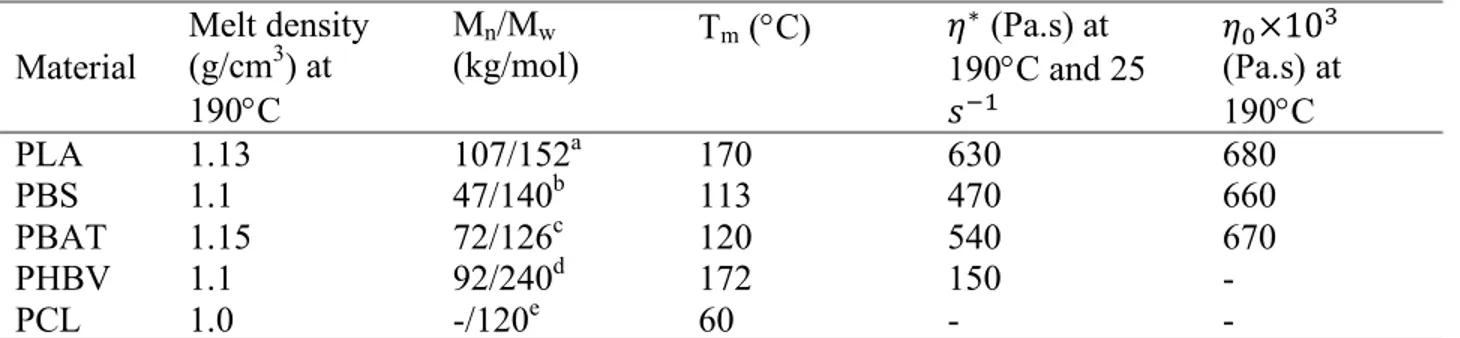
Table 4.1. Main characteristics of materials used in the study. ... 58
Table 4.2. Interfacial tension values (mN/m) at 190 °C. ... 64
Table 4.3. Spreading coefficients (mN/m) of two possible ternary blends in the present work. ... 68
Table 4.4. Continuity (%) results obtained from gravimetry experiments. ... 70
Table 5.1. Principal properties of the polymers used in the study. ... 86
Table 5.2. Average values of the geometrical constructions of the partially wet droplets in PLA/PHBV/PBS, PLA/PBAT/PE and PLA/PE/PBAT systems. ... 90
Table 5.3. Interfacial tension values (mN/m) at 190 °C. ... 91
Table 5.4. Spreading coefficients (mN/m) of the ternary blends. ... 91
Table 5.5. Interfacial concentration and particle growth rates of partially wet droplets at the interface during annealing. Comparison of growth rates with binary systems. ... 99
Table 5.6. Coarsening rates of the middle phase in ternary blends of PLA/PHBV/PBS and PLA/PBAT/PE vs. their constituent co-continuous binary blends during annealing. ... 101
Table 6.1. Materials used in this work. ... 115
Table 6.2. Effect of the third phase at the interface on the morphology characteristics of blends. ... 121
Table 6.3. Interfacial tension values and Spreading coefficients at 200 °C. ... 123
Table 6.4. Thermal properties of the pure polymers and binary blends. ... 124
Table 7.1. Main characteristics of materials ... 142
Table 7.2. Interfacial tension values and spreading coefficients at 200 °C. ... 146
Table 7.3. Mechanical properties of the pure components as well as binary, ternary and quaternary systems. ... 149
Table 7.4. Thermal properties of the pure polymers and binary, ternary, and quaternary blends. In the table a, b, and c denotes PLA, PA11 and PEBA respectively. ... 154
LIST OF FIGURES
Figure 2.1. Classifications of bioplastics based on the source and biodegradability. ... 6
Figure 2.2. The molecular structure of PLA. ... 7
Figure 2.3. The molecular structure of PBAT. ... 7
Figure 2.4. The molecular structure of PBS. ... 8
Figure 2.5. The molecular structure of PHBV. ... 8
Figure 2.6. The molecular structure of PA11. ... 9
Figure 2.7. Morphologies of immiscible polymer blends with their potential applications (Macosko, 2000). ... 10
Figure 2.8. Distortions of PA6 thread in PS matrix at 230 °C as a function of time from left to right (Xing et al., 2000). ... 12
Figure 2.9. Typical evolution of short fiber (ethylene vinyl alcohol copolymer in low density polyethylene at 200 °C) (Demarquette, 2003). ... 13
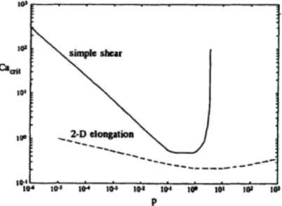
Figure 2.10. Critical capillary number vs. the viscosity ratio in simple shear and elongational flow fields (Grace, 1982). ... 16
Figure 2.11. Coalescence model. ... 19
Figure 2.12. (a) A schematic representing a typical evolution of morphology in a binary blend, (b) and (c) typical matrix/dispersed and co-continuous morphologies, respectively (S Ravati & Favis, 2010b)... 21
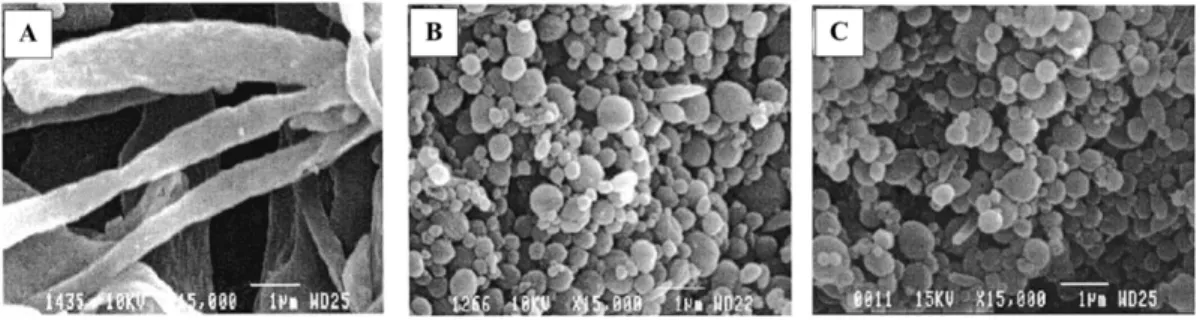
Figure 2.13. SEM photomicrographs of the dispersed HDPE phase after the matrix dissolution technique: (A) 5HDPE/95SEBS (Type I); (B) 5HDPE/95PS (Type II); (C) 5 HDPE/90 PS/20 SEBS (Type III) (J. M. Li et al., 2002). ... 24
Figure 2.14. The two wetting regimes for a drop on a substrate. ... 27
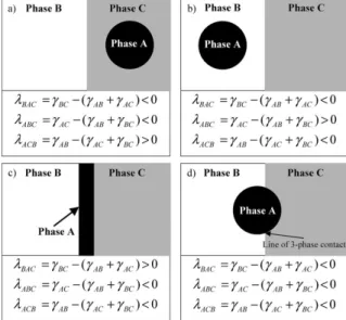
Figure 2.15. Possible equilibrium morphologies in a ternary polymer system composed of two major phases B and C and one minor phase A. The cases (a) to (c) describe complete wetting morphologies, and the case (d) displays partial wetting morphology (Virgilio, Marc-Aurele, et al., 2009). ... 28
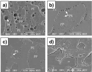
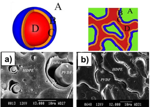
Figure 2.16. a) Triangular concentration diagram showing the composition of the various ternary HDPE/PS/PMMA blends examined in this study, b) various morphological states for ternary HDPE/PS/PMMA, and c) triangular concentration diagram showing the various regions (S Ravati & Favis, 2010b). ... 31 Figure 2.17. Evolution of the shell formation process with increasing PS content (vol. % based on the dispersed phase) for the 80(HDPE)/20(PS/L-PMMA) (cryo-fractured samples after being etched for 10 s with acetic acid) (Reignier & Favis, 2003a). ... 32 Figure 2.18. SEM micrographs of the 80 HDPE/20 (PS/PMMA), (I): (a) fractured surface etched with acetic acid for 2 min (14%PS/86%PMMA); (b) microtomed surface etched 24 h with cyclohexane (9%PS/91%PMMA); and (c) microtomed surface etched 24 h with cyclohexane (9%PS/91%PMMA), (a and b with high viscosity and c with low viscosity PMMA) (Reignier & Favis, 2003b); (II) (a) low viscosity PS/high viscosity PMMA, PMMA is extracted by acetic acid; PS encapsulates PMMA; (b) low viscosity PS/low viscosity PMMA, PMMA is extracted by acetic acid; PS encapsulates PMMA; (c) high viscosity PS/high viscosity PMMA, PS is extracted by cyclohexane; PMMA encapsulates PS (Reignier et al., 2003). ... 33 Figure 2.19. SEM micrograph of morphology of (a) and (b) 35/40/25 HDPE/PS/PMMA with low molecular weight PMMA after extraction of PMMA by acetic acid and extraction of PS by cyclohexane, respectively; (c) 35/40/25 HDPE/PS/PMMA with low molecular weight PMMA (cryofracture), (d) and (e) 35/40/25 HDPE/PS/PMMA with low molecular weight PMMA after extraction of PMMA by acetic acid and extraction of PS by cyclohexane (S Ravati & Favis, 2010b)... 35 Figure 2.20. SEM micrographs of morphology of HDPE/PP/PS 45/45/10 vol% blends (a) immediately after melt processing without SEB modifier; (b) without SEB modifier after 120 min of annealing time at 200 °C; (c) with 1% SEB based on the PS content after 120 min of annealing time at 200 °C; (d) with 15% SEB based on the PS content after 60 min of quiescent annealing time. Note that the PS phase has been extracted by cyclohexane (Virgilio, Marc-Aurele, et al., 2009) ... 36 Figure 2.21. SEM photomicrograph of a) 10/10/60/20 PMMA/PS/PP/HDPE, b) 10/60/20/20/10 PMMA/PS/PP/HDPE, c) 60/20/10/10 PMMA/PS/PP/HDPE, and d) 10/10/20/60 PMMA/PS/PP/HDPE (Guo, Gvozdic, et al., 1997). ... 39
Figure 2.22. (a) FIB-AFM images of (a) unmodified EPDM/PCL/PS/PLLA 45/45/5/5 blend after 30 min of quiescent annealing time, (b) the PS/PLLA/PS-b-PLLA sheath structure at the EPDM/PCL interface in the EPDM/PCL/PS/PLLA/PS-b-PLLA blend after 60 min of quiescent annealing; (c) morphology of the EPDM/PCL/PS/PLLA/PS-b-PLLA 45/45/5/5/(30 g/100 ml PLLA) blend annealed at 200 °C for 60 min; (d) SEM micrographs showing the asymmetric layer structure of the remaining PLLA + PS-b-PLLA material after 15 min of quiescent annealing time. The first micrograph clearly shows that one side of the layer is relatively smooth, while the other is rough and covered with submicron droplets; (e) the layer structure in the EPDM/PCL/PS/PLLA/PS-b-PLLA blend after the selective extraction of the PCL phase after 60 min of annealing (Virgilio, Sarazin, et al., 2010); (f) FIB-AFM images of the blends modified with the PS-b-PMMA copolymers after melt processing and 60 min of quiescent annealing time (Virgilio, Sarazin, & Favis, 2011). ... 40 Figure 2.23. SEM micrograph of a) onion morphology in an HDPE matrix for 60/13/13/13 HDPE/PS/PMMA/PVDF; b) triple-percolated morphology of 30/15/15/40 (microtomed surface) (PMMA extracted) (S Ravati & Favis, 2010a). ... 42 Figure 4.1. Complex viscosity vs. frequency of the neat polymers at 190°C. ... 59 Figure 4.2. a) The breakup of the PLA thread in the matrix of PBAT; and b) The retraction of the imbedded fiber of PLA in the matrix of PBS at 190°C. ... 64 Figure 4.3. a) SEM and b) AFM micrographs of the partially wet system of 50/5/45 PLA/PBS/PCL. Note that the geometrical construction in (b) is used to measure the interfacial tension ratios between components. ... 65 Figure 4.4. a) FTIR-imaging micrograph of 33/33/33 PLA/PBS/PBAT; b, c, d) FTIR spectra of points “A, B, and C” on FTIR-image versus pure components of PLA, PBS, and PBAT, respectively. ... 66 Figure 4.5. a) SEM, b) FTIR-image, c) AFM micrograph of PLA/PBS/PBAT 20/40/40 vol% blend after 10 min of annealing at 190 °C. Note that the PLA and PBAT phases have been extracted using tetrahydrofuran in the SEM micrograph and the white bars indicate 10 µm. ... 68 Figure 4.6. a) AFM micrograph of 33/33/33 PLA/PBS/PBAT blend; b) SEM micrographs of 33/33/33 PLA/PBS/PBAT blend after PLA and PBAT are extracted by tetrahydrofuran. ... 69
Figure 4.7. SEM micrographs of PLA/PBS/PBAT 33/33/33 (a) before and (b) after annealing for 10 min at 190 °C. Note that tetrahydrofuran has been used to completely extract PLA and partially influence PBAT. ... 70 Figure 4.8. Micrographs of 25/25/25/25 PLA/PBS/PBAT/PHBV: a, b) AFM images; SEM images c) after extraction of PLA and PBAT using tetrahydrofuran and d) after extraction of all components except PHBV using dichloromethane. ... 71 Figure 4.9. a) FTIR-imaging (PLA: green; PHBV: orange; PBS: dark blue; PBAT: light blue) and b) the close-up AFM micrographs of 25/25/25/25 PLA/PBS/PBAT/PHBV after 10 min of annealing at 190 °C. ... 72 Figure 4.10. SEM micrographs of a and a’) PBAT/PBS/PHBV 33/33/33 before and after annealing for 10 min at 190°C, respectively; b and b’) PBAT/PBS/PHBV 10/45/45 before and after annealing for 10 min at 190°C, respectively. ... 73 Figure 4.11. SEM micrographs of quaternary PLA/PBS/PBAT/PHBV blends: a) and a') 25/25/25/25 after 10 and 30 min of annealing respectively; b) and b’) 30/30/10/30 after 10 and 30 min of annealing respectively. ... 74 Figure 5.1. a) The equilibrium interfacial tensions at a 3-phase line of contact in a ternary A/B/C system with the corresponding Neumann triangle. AFM micrographs demonstrating contact angles in b, b’) PLA/PHBV/PBS 50/5/50, c, c’) PLA/PBAT/PE 50/5/50, and d, d’) PLA/PE/PBAT 50/5/50. ... 90 Figure 5.2. SEM micrographs of 50/x/50 PLA/PHBV/PBS with different concentrations of PHBV annealed for 10 min: a) 5%, b) 10%, c) 20%, d) 33%. ... 92 Figure 5.3. a) Diagram of diameter (d) of PHBV droplets in the PLA/PHBV/PBS 50/5/50 system as a function of annealing time and b) diagram of PHBV layer thickness in PLA/PHBV/PBS 50/x/50 with 15, 20, and 33% of PHBV compared with the predictions of PHBV coarsening in binary 50/50 PLA/PHBV (dashed line) and 50/50 PHBV/PBS (dashed-dotted line) as functions of annealing time. ... 93 Figure 5.4. AFM and SEM micrographs of the PLA/PBAT/PE 50/x/50 system at 0, 5 and 10 minutes quiescent annealing. a, a’, and a” are with 5% PBAT and b, b’, and b”) are with 10% PBAT. The white bars denote 10 µm. ... 95
Figure 5.5. a) PBAT droplet length or layer thickness as a function of annealing time in PLA/PBAT/PE 50/x/50 system with 5 and 10% of PBAT. b) PE droplet diameter (d) as a function of annealing time in PLA/PE/PBAT 50/x/50 system with 5, 10, and 20% of PE. .. 95 Figure 5.6. SEM micrographs of the PLA/PE/PBAT 50/x/50 system with 5, 10, and 20% of PE annealed for 5, 10, and 30 min. The white bars denote 10 µm. ... 96 Figure 5.7. PE number-average droplet size as a function of composition comparing the confined partially wet droplets in the ternary blends with that for dispersed PE droplets in binary blends. ... 97 Figure 5.8. Diagrams of the third power of the number average diameter (d3) as a function of annealing time: a) 5% PHBV in PLA/PHBV/PBS, 5% PBAT in PLA/PBAT/PE and 5% PE in PLA/PE/PBAT; b) 5, 10 and 20% PE in PLA/PE/PBAT. ... 98 Figure 5.9. The range of morphological structures observed in this work based on dewetting behavior, composition and annealing time. ... 104 Figure 6.1. Schematics demonstrating complete and partial wetting morphologies in ternary polymer blends of minor component of A and two major components of B and C with the corresponding spreading coefficients. ... 113 Figure 6.2. SEM micrographs of a) PLA/PA11 50/50, the PLA phase is extracted by chloroform; PLA45%/PBS10%/PA45%: b) after extraction of both PLA and PBS by chloroform, c) after extraction of PLA by THF; d) PLA45%/PBAT10%/PA45%, the PBAT phase is extracted by TCP; e) PLA45%/EMA10%/PA45%, the EMA phase is extracted by cyclohexane; f) PLA45%/EMA-GMA10%/PA45%, the EMA-GMA phase is extracted by cyclohexane. . 119 Figure 6.3. AFM micrographs of a) PLA45%/PBS10%/PA45%; b) PLA45%/PBAT10%/PA45%; c) PLA45%/EMA10%/PA45%; d) PLA45%/EMA-GMA10%/PA45%. ... 120 Figure 6.4. Tensile stress-strain plots of PLA, the binary PLA/PA 50/50 blend, and ternary blends containing 10% of different third components. ... 126 Figure 6.5. Mechanical properties of pure components and blends containing 10% of different types of third components. ... 127
Figure 6.6. SEM micrographs of the fracture surface of the binary PLA/PA11 50/50 blend at a) the vicinity of the notch of impact fractured specimen; b) a cryo-fractured cross-section underneath the impact fracture surface. ... 128 Figure 6.7. SEM micrographs of the Izod fracture surface at the notch root of the PLA/PA 50/50 blends containing 10% of a) PBS; b) PBAT; c) EMA; and d) EMA-GMA. ... 129 Figure 6.8. SEM micrographs of the fracture surface of a cross-section underneath the impact fracture surface of the PLA/PA 50/50 blends containing 10% of a) PBS; b) PBAT; c) EMA; and d) EMA-GMA. ... 130 Figure 6.9. Schematic of the toughening process in PLA/EMA/PA11 with cavitated partially wet droplets percolating the PLA/PA11 interface throughout the sample. ... 131 Figure 7.1. SEM micrographs of PLA/PEBA/PA11 45/10/45 a) cryo-fractured surface, b) PLA solvent extracted surface. The white bars denote 10 µm. ... 147 Figure 7.2. SEM and AFM micrographs of a) PLA/PEBA/PA11 x/10/y and b) PLA(PEO)/PEBA/PA11 x(20)/10/y. The white bars denote 10 µm. ... 147 Figure 7.3. Impact strength as a function of PEBA content in PLA/PEBA/PA11 where the PLA:PA11 ratio is maintained at 1:1 (◆) and PLA(PEO)/PEBA/PA11 with 20% PEO (based on the PLA content) and a PLA:PA11 ratio of 1:1. (■). Also shown is the PEBA interfacial coverage (
•
) in both the ternary and quaternary systems as a function of PEBA content. .. 150 Figure 7.4. Impact strength as a function of PEO content in PLA(PEO)PEBA/PA11 with 45PLA(xPEO)/10PEBA/45PA11. ... 151 Figure 7.5. Impact strength (□) as a function of the weight content of PLA in PLA/PEBA/PA11 with 10% PEBA. Phase continuity of PLA (●) or PA11 (◆) in the same blends. ... 152 Figure 7.6. Impact strength (■) as a function of the weight content of PLA in PLA(PEO)/PEBA/PA11 with 10% PEBA and 20% PEO based on the PLA content. Phase continuity of PLA(PEO) (●) or PA11 (◆) in the same blends. ... 153 Figure 7.7. SEM micrographs of the impact fracture surface adjacent to the notch of a) neat PLA, b) PLA/PA11 50/50, c) PLA/PEBA/PA11 27/10/67, d) PLA/PEBA/PA11 45/10/45, e) PLA(PEO)/PEBA/PA11 27(20)/10/67 and f) PLA(PEO)/PEBA/PA11 45(20)/10/45. ... 155Figure 7.8. SEM micrographs of the cryo-fractured surface of a cross-section underneath the impact fracture surface of the PLA(PEO)/PEBA/PA11 45(20)/10/45 blend showing cavitation. .. 157 Figure 7.9. Schematic of toughening in the PLA(PEO)/PEBA/PA11system comprised of a 3D interconnected network of a cavitated middle rubbery PEBA layer. The dashed lines along the rubbery layer demonstrate an effective stress-field surrounding the layer. ... 158
LIST OF SYMBOLS AND ABBREVIATIONS
Symbols: 𝛼 amplitude of distortion 𝐶𝑎 Capillary number 𝜇 chemical potential 𝐺∗ complex modulus 𝜃( contact angleℎ*+,- critical thickness of film between two drops in rupture 𝜌 density of polymers
𝜈 dewetting speed
𝐷 diameter
𝑝 dispersed phase/matrix viscosity ratio 𝛾,3 dispersive component of surface tension
𝜂( effective viscosity
𝑁6 first normal stress difference
𝜒89 Flory-Huggins interaction parameter
𝜔 frequency
𝐺 Gibbs free energy 𝛾,;/𝛾 interfacial tension 𝐺== loss modulus
𝑀? molecular weight of the polymers
𝑛 number of moles
𝛾,A polar component of surface tension ∆𝑃 pressure difference
𝑃* probability of the droplet collision
𝑅 radius
𝛾 shear rate
𝜆 spreading coefficient
𝐹 Stokes drag force
𝐺= storage modulus
𝛾 surface/interfacial tension
Ω Tomotika function
𝜂 viscosity
𝜑 volume fraction
𝜂I zero shear viscosity
Abbreviations:
ABS acrylonitrile-butadiene-styrene AFM atomic force microscopy ATBC acetyl tri-n-butyl citrate
BT breaking thread
DSC differential scanning calorimetry
EBA-GMA ethylene/n-butyl acrylate/glycidyl methacrylate copolymer EMA ethylene methyl acrylate
EMA-GMA ethylene-methyl acrylate-glycidyl methacrylate
EMAA-Zn zinc ionomer of ethylene/methacryalic acid copolymer EPDM ethylene-propylene-diene terpolymer
FTIR Fourier transform infrared spectroscopy HDPE high density polyethylene
HDT heat deflection temperature HIPS high impact polystyrene IFR imbedded fiber retraction LbL layer-by-layer
NT Neumann triangle
PA11 polyamide-11 PA6 polyamide 6 PANI polyaniline
PBAT poly(butylene adipate-co-terephthalate) PBS poly(butylene succinate)
PBT polybutylene terephthalate
PC polycarbonate
PCL polycaprolactone PDLA poly(D,L-lactic acid)
PE polyethylene
PEBA poly(ether-b-amide) PEG polyethylene glycol PEO poly(ethylene oxide)
PHBV poly(3-hydroxybutyrate-co-hydroxyvalerate) PLA polylactide
PLLA poly(L-lactic acid) PMMA polymethyl methacrylate
PO polyolefin
POE polyethylene-octene elastomer
PP polypropylene PPG poly(propylene glycol) PS Polystyrene PSS poly(styrene sulfonate) PVC poly(vinyl chloride) PVDF polyvinylidene fluoride SAN styrene acrylonitrile resin SBR styrene-butadiene rubber
SEB styrene-(ethylene-butylene) diblock
SEBS styrene-ethylene/butylene-styrene copolymer SEM scanning electron microscopy
TCP 1,2,3-trichloropropane THF Tetrahydrofuran TPS thermoplastic starch
TPSA thermoplastic starch acetate TPU thermoplastic polyurethane
LIST OF APPENDICES
Appendix A – Suppoting information for article 2 ... 191 Appendix B – Suppoting information for article 3 ... 194
CHAPTER 1
INTRODUCTION AND OBJECTIVES
1.1 Introduction
Plastics have become an important aspect of our everyday lives. Synthetic plastics such as polyethylene (PE), polypropylene (PP), polystyrene (PS), polyethylene terephthalate (PET), and polyvinyl chloride (PVC) share a major portion of commodity plastics. The environmental concerns and limited fossil fuel resources compel industrial sectors and scientists to find alternatives to current petroleum-based plastics. Biodegradable plastics are generating significant interest in various industries because of their true potential for reducing the dependence on fossil-based resources and their related environmental impacts (Avérous & Pollet, 2012). The bioplastics and biopolymers market is projected to grow at a compound annual growth rate of 12% between 2016 to 2021 (MarketsandMarkets, 2016). The growth of the market is attributed to the stringent environmental regulations across the globe, compelling the manufacturer to reduce the carbon content in their products, and fluctuations in the price of petroleum, which forces companies to search for a stable source of raw materials. The production and applications of bioplastics, nevertheless, are still limited due to their high production cost and poor performance characteristics as compared to the commodity plastics (MarketsandMarkets, 2015; L Shen, Haufe, & Patel, 2009). Polylactides are the leading bioplastics, which have been looked upon as sustainable alternatives to petroleum based plastics over the last decade (Babu, O’Connor, & Seeram, 2013; Erickson & Winters, 2012; Li Shen, Worrell, & Patel, 2010; Williams & Hillmyer, 2008). These polymers are biodegradable aliphatic polyesters derived from renewable resources, such as corn and starch, and has generated much interest due to its mechanical properties and favorable economics (Auras, Lim, Selke, & Tsuji, 2010). However, PLA suffers from inferior impact toughness and thermal stability when compared to the conventional polymers and this limits its wider applications. Previously, PLA was only used for biomedical applications but there is a strong increase in the number of research papers and patent applications pertaining to the modification of PLA in order to develop it as a high performance plastic. PLA must meet and even surpass the mechanical properties expected from petroleum based polymers such as high impact polystyrene (HIPS), acrylonitrile butadiene styrene (ABS), and high impact polyamides in order to successfully replace these plastics in value added applications. Different strategies have been mentioned in the literature to improve
the poor toughness and impact strength of PLA such as copolymerization, plasticization and blending with other bioplastics (Anderson, Schreck, & Hillmyer, 2008; H. Liu & Zhang, 2011; Rasal, Janorkar, & Hirt, 2010).. Generally, polymer blending is considered as an important route to overcome the mechanical property deficiencies of PLA since it is the most versatile and cost-effective approach which is easily adapted to the classic compounding capabilities. PLA has been blended with different polymers to prepare materials with the desired set of properties (Anderson et al., 2008; Paul & Bucknall, 2000).
A remarkable research has been reported on binary polymer blends with a matrix/dispersed or co-continuous phase morphology, nevertheless, understanding the development of complex morphologies in multiphase polymers is still a major challenge in the field of polymer blending. To achieve the desired properties, we need to acquire a good knowledge of structure-property relationships in such systems. Generally, for a multiple phase system two distinct broad category of wetting regimes are possible: complete wetting and partial wetting (de Gennes, Brochard-Wyard, & Quere, 2004; Torza & Mason, 1970). Complete wetting is the most stable thermodynamic state where one phase segregates the two other phases from each other in a ternary system. In contrast, partial wetting is the thermodynamically favorable structure where all phases form a three phase contact and none of the phases completely spreads at the interface of the two others. The majority of studies of ternary immiscible polymer blends deal with complete wetting behavior in which interfacial dynamics can result in a broad range of phase separated structures. It has been shown that through control of composition, interfacial dynamic, and viscoelastic properties of components of a multiphase polymer blend, encapsulated structures can be converted to multiple percolated structures such as the transition of core-shell droplets to tri-continuous structure in a ternary blend (S Ravati & Favis, 2010a, 2010b; Reignier & Favis, 2000a; J. H. Zhang, Ravati, Virgilio, & Favis, 2007). Ravati and Favis (S Ravati & Favis, 2010a) conducted a detailed composition-morphology analysis of binary, ternary, quaternary, and quinary model systems and generated multiple percolated and onion-type structures. The formation of partially wet droplets has just begun to be reported in ternary and quaternary systems (Horiuchi, Matchariyakul, Yase, & Kitano, 1997; Virgilio, Marc-Aurele, & Favis, 2009). Virgilio et al. (Virgilio, Marc-Aurele, et al., 2009) were first to detail the generation of an entirely novel close-packed droplet array of polystyrene (PS) at the interface of high density polyethylene (HDPE) and polypropylene (PP).
However, it is still not clear how the incorporation of partially wet droplets can influence the mechanical properties in a ternary system.
Binary blends of PLA with other polymers are among the most widely studied bioplastic systems (H. Bai et al., 2012; Imre et al., 2013; Z. Liu, Luo, Bai, Zhang, & Fu, 2016a; Ojijo, Ray, & Sadiku, 2013; Stoclet, Seguela, & Lefebvre, 2011; Thurber, Xu, Myers, Lodge, & Macosko, 2015; M. Wu, Wu, Wang, Zhang, & Fu, 2014), however, researchers have shown an increased interest in multicomponent blends with PLA (H. Liu, Chen, Liu, Estep, & Zhang, 2010; K. Zhang, Mohanty, & Misra, 2012). High performance polymeric materials with high levels of toughness, mechanical strength, and thermal resistance can be obtained by combining plastics with complementary properties (Yongjin Li & Shimizu, 2009; H. Liu, Song, Chen, Guo, & Zhang, 2011; Luzinov, Pagnoulle, & Jerome, 2000a). They usually exhibit a more balanced performance compared with binary systems where improvement in one property can lead to a substantial decrease in other properties. However, a wide variety of complex morphologies in the study of ternary and quaternary polymer blends have been reported which must be determined and quantified in the case of bioplastic based multicomponent systems. The formation of a variety of partial and complete wet structures has been reported in ternary blends of bioplastics with some novel tunable morphologies (Sepehr Ravati & Favis, 2013b). To the best of our knowledge, little attention has been paid to the detailed characterization and control of the morphology in multiphase bioplastic blends, despite the clear role of phase morphology in controlling the physical properties (Dou et al., 2015; Luzinov, Xi, Pagnoulle, Huynh-Ba, & Jerome, 1999; Sepehr Ravati, Beaulieu, Zolali, & Favis, 2014). What is still unknown are how the development of morphologies such as multiple encapsulated, multiple percolated as well as partially wet structures contribute to the mechanical properties and particularly the toughness of multiple phase bioplastic blends. In addition, the effect of the level of continuity and interfacial interactions of phases are required to be thoroughly investigated in such heterophase systems.
1.2 Objectives
The main objective of this project is to control the morphology in ternary and quaternary PLA-based blends to generate ultratough materials. Thus, the following sub-objectives are envisaged as the main milestones to achieving the main objective of this research:
a) Establish the principal parameters which control partially and completely wet morphological structuring in ternary and quaternary PLA-based blends.
b) Determine the effect of partially wet droplets on the mechanical performance of co-continuous PLA-based systems.
c) Establish the correlation between the tri-continuous structure and mechanical properties of co-continuous PLA-based blends.
d) Develop ultratough materials based on partial and complete wetting in PLA-based blends. In this work, the structuring of morphology in blends composed of the most relevant bioplastics with PLA are investigated. The effect of composition and interfacial dynamics on the morphology development of the ternary and quaternary systems are studied in detail. A simple melt mixing method, either using internal melt mixing or twin screw extrusion, is used to generate new structures based on two wetting behaviors of partial and complete wetting. The effect of these wetting behaviors on mechanical properties, and in particular notched Izod impact toughness, is examined. Attempts are made to understand the relationship between these structures and the mechanical properties.
CHAPTER 2
LITERATURE REVIEW
2.1 Biobased and Biodegradable plastics
Bioplastics have been used for food, furniture, and clothing for many years. In the 1860s, the first bioplastic namely “Celluloid” was invented and since then many other biobased polymers from renewable resources were developed. However, their development remained at the laboratory stage due to the discovery of crude oil and production of synthetic petroleum-based polymers in the 1930s and 1940s. Nowadays, the environmental concerns and limited fossil fuel resources motivated scientists and industrial sectors to find alternatives to petroleum-based polymers. Bioplastics are newly emerging materials which are expected to completely replace petroleum-based plastics. The term bioplastics or biopolymers refers to a whole family of polymeric materials which are either biodegradable or biobased, or both. Biodegradable means that the product degrades under certain conditions. Two specific standards, EN 13432 and ASTM D-6400, classify the biodegradable or compostable plastics fate. Based on the EN 13432 standard, a plastic must undergo 90% degradation in a lab within 180 days to be called biodegradable while this condition is 60% degradation threshold within 180 days for ASTM D-6400. On the other hand, when a significant portion of carbon in a polymeric product comes from renewable resources, it will be considered as a bioplastic per the ASTM D6866 standard. The most relevant biobased and biodegradable plastics are presented in Figure 2.1.
Bioplastics still present relatively small volume of the global plastic production; however, according to the recently published report by the Utrecht University (L Shen et al., 2009), the worldwide capacity of bioplastics will increase from 360 Kt in 2007 to 2.33 Mt in 2013 and to 3.45 Mt in 2020. Also, based on this report, the most important bioplastics in terms of production volume are starch plastics and PLA with 150 Kt for each product which are expected to increase to 1.3 Mt and 800 Kt by 2020, respectively. Biobased polyethylene with production volume of 600 Kt will be amongst the most influential bioplastics by 2020. However, bioplastics must provide the cost-performance requirements of the commodity polymers to be accepted as an alternative for the petroleum-based polymers. The available materials on the market suffer from some performance weaknesses such as low heat deflection, brittleness, processing window sensitivity, barrier
properties, and final product cost which limits their wider applications. The following section summarizes the most relevant bioplastics.
Figure 2.1. Classifications of bioplastics based on the source and biodegradability.
2.1.1 Poly(lactide)
Poly(lactic acid) or polylactide (see Figure 2.2) is one of the most promising biodegradable and compostable aliphatic polyesters derived from renewable sources, such as corn and sugar, which has received marked industrial and scientific attentions in research over the last decades (Auras et al., 2010; Jamshidian, Tehrany, Imran, Jacquot, & Desobry, 2010; Lim, Auras, & Rubino, 2008; Martin & Avérous, 2001). The polycondensation of lactic acid and the ring opening polymerization of lactide, the cyclic diester of lactic acid, are two methods which PLA can be produced by, while the ring opening polymerization is the more commonly used method. Commercial PLA grades are copolymers of poly(L-lactic acid) (PLLA) and poly(D,L-lactic acid) (PDLLA), in which the ratio
of L- to D,L-enantiomers affects the properties of PLA, however, the mechanical properties are not
significantly influenced by the synthesis method (Ajioka, Enomoto, Suzuki, & Yamaguchi, 1995; Sodergard & Stolt, 2002). Generally, PLA is a rigid, semi-crystalline polymer with tensile strength in the range of 50-70 MPa and elastic modulus of 3000-4000 MPa, and elongation at break of 2-5% (Perego & Cella, 2010). Mechanical properties of PLA including tensile strength, tensile modulus, and crystallinity are affected by the molecular weight, structure, and crystallinity of PLA (Engelberg & Kohn, 1991). Applications of PLA due to its good appearance, high mechanical strength, and relatively good barrier properties are broadened especially in the packaging industry (Jamshidian et al., 2010; Lim et al., 2008). Several companies such as Natureworks LLC, Mitsui
Biopolymers Synthetic /biodegradable Polycaprolact one (PCL) Poly(butylene adipate-co-terephthalate) (PBAT) Poly(butylen e succinate) (PBS) Biobased /biodegradable Polylactic acid (PLA) Polyhydroxya lkanoates (PHAs) Polysaccharid es Proteins, lipids Biobased /non-biodegradable Biobased Polyolefins (PE & PP) Polyamides (PA11)
Chemicals produce PLA which Ingeo the brand of PLA produced from corn and other feedstock by Natureworks LLC is commercially available in the market.
Figure 2.2. The molecular structure of PLA.
Although PLA has many advantages such as excellent biocompatibility, eco-friendly properties, better thermal processing as well as less energy dependence compared to petroleum-based plastics that distinguish this bioplastic from the other available biopolymers, it has some drawbacks which limit its broader applications. The main weaknesses of PLA are poor toughness and low heat deflection temperature (Auras et al., 2010; Rasal et al., 2010).
2.1.2 Poly(butylene adipate-co-terephthalate)
Poly(butylene adipate-co-terephthalate) (PBAT) is an aliphatic-aromatic copolyester which has been commercialized by BASF and Eastman under the trademarks of Ecoflex and Easter Bio, respectively. The molecular structure of PBAT consists of butylene terephthalate (BT) and butylene adipate (BA) segments as shown in Figure 2.3. PBAT is a flexible and ductile biodegradable polymer which degrades within a few weeks with the aid of naturally occurring enzymes (Gu, Zhang, Ren, & Zhan, 2008). Witt et al. (Witt et al., 2001) assessed the risk of introduction of PBAT into composting process and found that there is no indication for an environmental risk as well as no significant toxicological effect after degradation. Considering its high toughness and biodegradability, PBAT is a good candidate for toughening of biobased plastics such as PLA, PHAs, etc. while retaining the biodegradability of the final materials. Ecovio® is the commercial trademark of the blend of PLA/PBAT which is currently produced by BASF and shows the importance of PBAT in commercial applications.
2.1.3 Poly(butylene succinate)
Poly(butylene succinate) (PBS) (Figure 2.4), is a biodegradable polymer with possibility to be produced both from renewable and non-renewable resources. Its building monomers, i.e. 1, 4-butanediol and succinic acid, can be derived from renewable feedstocks (Florence & Mechael, 2015; Ichikawa & Mizukoshi, 2012; Momoko Ishii, Masaki Okazaki, Yuji Shibasaki, Ueda*, & Teranishi, 2001; Shirahama, Kawaguchi, Aludin, & Yasuda, 2001). PBS is a semi-crystalline thermoplastic polyester which exhibits balanced performance in thermal and mechanical properties, i.e. high heat deflection temperature and toughness, and has been extensively studied for potential applications as a feasible green polymer.
Figure 2.4. The molecular structure of PBS.
2.1.4 Poly(3-hydroxybutyrate-co-hydroxyvalerate)
Poly(3-hydroxybutyrate-co-hydroxyvalerate) (PHBV) is among one of the biggest group of biopolyesters, i.e. polyhydroxyalkanoates (PHA), which are directly produced by bacterial fermentation of sugars or lipids. It is also completely biosynthetic and biodegradable with zero toxic waste and recyclable into organic waste (Braunegg, Lefebvre, & Genser, 1998; Corre, Bruzaud, Audic, & Grohens, 2012). PHBV shows excellent thermal resistance and biodegradability that provide many potential applications in packaging and biomedical. Its chemical structure is shown in Figure 2.5.
2.1.5 Polyamide 11
Polyamide (PA) polymers, which can be derived from biobased resources such as castor oil(Rulkens & Koning, 2012), are engineering plastics with high thermal stability impact and chemical resistance as well as excellent dimensional stability. The main application of PA11 is in automotive and flexible pipe applications for offshore oilfield exploration. The typical water absorption characteristics of PA11 is significantly reduced because of the high hydrocarbon proportion of the repeat unit in comparison with those of PA6 and polyamide 66. The molecular structure of PA11 is presented in Figure 2.6.
Figure 2.6. The molecular structure of PA11.
2.2 Polymer Blends
2.2.1 Miscibility
The miscibility of binary polymer mixtures can be assessed by the Gibbs free energy of mixing:
∆𝐺J= 𝑅𝑇𝜒89𝜑8𝜑9+ 𝑅𝑇 𝜌8𝜑8ln 𝜑8 𝑀?P +
𝜌9𝜑9ln 𝜑9
𝑀?Q (2.1)
where ∆𝐺J is Gibbs free energy of mixing, 𝜒89 is the Flory-Huggins interaction parameter, 𝜑, is the volume fraction of the polymer components, 𝜌, is the density of polymers, 𝑀?R is the molecular weight of the polymers, and R and T are gas constant and absolute temperature, respectively. This equation shows that Gibbs free energy includes the enthalpy and the entropy of mixing, the first and the second terms on the right side of the equation. Three classes of polymer blends are defined: a) miscible polymer blends which show ∆𝐺J < 0 and 𝜕V∆𝐺 𝜕𝜑V > 0 over the entire composition
range; b) partial miscible polymer blends which only demonstrate miscibility in some compositions; and c) immiscible polymer blends which always possess ∆𝐺J> 0 and 𝜕V∆𝐺 𝜕𝜑V < 0. Most polymer mixtures are categorized as immiscible systems since the entropy
of mixing is negligible due to high molecular weights and a low degree of freedom of polymers. In addition, the mixing of polymers is usually endothermic which results in a positive Gibbs energy of mixing. The morphology of immiscible phases in an immiscible polymer blend significantly influence the final properties and can be manipulated towards achieving desired set of properties. Figure 2.7 shows the main possible phase morphologies in binary polymer blends and their potential applications. It will be shown later that interfacial tension between components is dominant factor controlling the final morphology in immiscible polymer blends.
Figure 2.7. Morphologies of immiscible polymer blends with their potential applications (Macosko, 2000).
2.2.2 Interfacial Tension
The interfacial tension between the components of a blend is one of the most important parameters significantly influences the morphology and performance of the polymer blend. The interfacial tension is defined as the reversible work required to create an interfacial area by the unit of area between two immiscible phases (S Wu, 1982). Interfacial tension originates from the imbalanced molecular forces at the interface as compared to the bulk and has the same unit as the surface
tension (N/m or J/m2). Experimental techniques used to determine interfacial tension can be divided into two categories: static (pendant drop, sessile drop and spinning drop) and dynamic (breaking thread, imbedded fiber retraction and deformed drop retraction) methods as well as estimation from surface tension and rheological techniques (Demarquette, 2003; Xing, Bousmina, Rodrigue, & Kamal, 2000). Some of the main techniques that are used to determine the interfacial tension between two polymers are briefly reviewed below.
2.2.2.1 Estimation from surface tension
One of the widely used methods to determine interfacial tension between polymers is to estimate it from the surface energy data of pure components. Harmonic and geometric mean equations have been proposed by Wu (Souheng Wu, 1971, 1974) for systems with low and high surface energies, respectively: 𝛾6V = 𝛾6+ 𝛾V− 4 𝛾63𝛾V3 𝛾63+ 𝛾 V3 + 𝛾6 A𝛾 VA 𝛾6A+ 𝛾VA 𝐻𝑎𝑟𝑚𝑜𝑛𝑖𝑐 𝑚𝑒𝑎𝑛 𝑒𝑞𝑢𝑎𝑡𝑖𝑜𝑛 (2.2) 𝛾6V = 𝛾6 + 𝛾V− 2 𝛾63𝛾 V3+ 𝛾6A𝛾VA 𝐺𝑒𝑜𝑚𝑒𝑡𝑟𝑖𝑐 𝑚𝑒𝑎𝑛 𝑒𝑞𝑢𝑎𝑡𝑖𝑜𝑛 (2.3)
where 𝛾,; is the interfacial tension, 𝛾,3 and 𝛾
,A are the dispersive (or nonpolar) and polar components
of the surface tension, respectively. 2.2.2.2 Breaking Thread Method
In this technique, a thread of a given polymer sandwiched between two films of another polymer is heated at a desired temperature until it breaks up into several small droplets. When heated above the melting temperature of both polymers, distortions forms at the surface of the thread due to pressure differences between the inside and outside of the thread. Interfacial tension and a tendency to minimize the interfacial area intensify these distortions when the wavelength of distortions becomes greater than the initial thread circumference. Elemans et al. (Elemans, Janssen, & Meijer, 1990) showed that the amplitude of the sinusoidal distortions can be described by Tomotika’s theory (Tomotika, 1935):
𝛼 = 𝛼I𝑒f- (2.4)
where 𝛼I is the initial amplitude of distortions and 𝑞 is the growth rate and is defined as:
𝑞 =𝛾6VΩ 𝑥, 𝑝
𝜂I𝐷I (2.5)
in which 𝛾6V is the interfacial tension between two liquids, 𝜂I is the zero shear viscosity of the
matrix, 𝐷I is the initial thread diameter, and Ω 𝑥, 𝑝 is a function tabulated by Tomotika and is a function of the viscosity ratio 𝑝 between the thread and matrix. Figure 2.8 shows a typical breakup process of a PA6 thread in a matrix of PS at 230 °C.
Figure 2.8. Distortions of PA6 thread in PS matrix at 230 °C as a function of time from left to right (Xing et al., 2000).
2.2.2.3 Imbedded Fiber Retraction Method
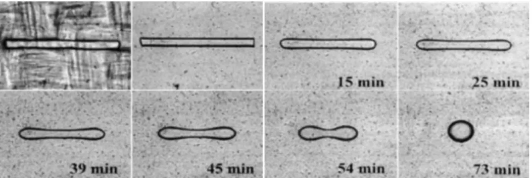
This technique is similar to the breaking thread method but with a shorter thread to prevent the thread breakup process. Thus, the initial length/diameter ratio of the fiber should be less than 12 (Demarquette, 2003; Xing et al., 2000). Figure 2.9 shows the evolution of a short thread during a retraction experiment. The short fiber relaxes back to a sphere which this process is function of the interfacial tension and viscosity ratio between fiber and matrix. The theory for this technique was first proposed by Carriere and Cohen (Carriere, Cohen, & Arends, 1989; Cohen & Carriere, 1989).
They showed that the evolution of the radius of the imbedded fiber can be described by the following equation: f 𝑅(𝑡) 𝑅3 − f 𝑅(0) 𝑅3 = 𝑡 𝛾 𝑅3𝜂( (2.6)
where 𝑅(𝑡) is the radius at time t, 𝑅(0) is the initial radius, 𝑅3 is the radius of the final spherical droplet, t is time, 𝛾 is the interfacial tension, and 𝜂( is the effective viscosity which is given by:
𝜂( =𝜂J+ 1.7𝜂3
2.7 (2.7)
in which 𝜂J and 𝜂3 are the zero shear viscosities of the matrix and fiber, respectively. The function used in Equation 2.7 is defined as:
f 𝑥 =3 2ln 1 + 𝑥 + 𝑥V 1 − 𝑥 + 36.p 2 arctan 3 𝑥 2 + 𝑥 − 𝑥 2− 4 𝑥V (2.8)
where x is 𝑅(𝑡) 𝑅3. It has been shown that the plot of f 𝑅(𝑡) 𝑅3 − f 𝑅(0) 𝑅3 vs time is linear (Demarquette, 2003; Xing et al., 2000). Thus, one can calculate the interfacial tension from the slop of a linear fit to the data with the knowledge of the effective viscosity and final droplet radius.
Figure 2.9. Typical evolution of short fiber (ethylene vinyl alcohol copolymer in low density polyethylene at 200 °C) (Demarquette, 2003).