HAL Id: hal-00798335
https://hal.archives-ouvertes.fr/hal-00798335
Submitted on 8 Mar 2013
HAL is a multi-disciplinary open access
archive for the deposit and dissemination of sci-entific research documents, whether they are pub-lished or not. The documents may come from teaching and research institutions in France or abroad, or from public or private research centers.
L’archive ouverte pluridisciplinaire HAL, est destinée au dépôt et à la diffusion de documents scientifiques de niveau recherche, publiés ou non, émanant des établissements d’enseignement et de recherche français ou étrangers, des laboratoires publics ou privés.
A simple yet efficient algorithm to turn one oriented
triangular mesh connectivity into another
Jérémy Espinas, Raphaëlle Chaine, Pierre-Marie Gandoin
To cite this version:
Jérémy Espinas, Raphaëlle Chaine, Pierre-Marie Gandoin. A simple yet efficient algorithm to turn one oriented triangular mesh connectivity into another. [Research Report] Université de Lyon; Université Lyon 1 - Claude Bernard. 2012. �hal-00798335�
A simple yet efficient algorithm to turn one oriented triangular
mesh connectivity into another
J´er´emy Espinas Rapha¨elle Chaine Pierre-Marie Gandoin
Universit´e de Lyon, CNRS Universit´e de Lyon, CNRS Universit´e de Lyon, CNRS Universit´e Lyon 1, LIRIS Universit´e Lyon 1, LIRIS Universit´e Lyon 2, LIRIS
France France France
[email protected] [email protected] [email protected]
Abstract
This paper addresses the problem of efficiently turning the connectivity of an initial triangular mesh into a new one, using combinatorial edge flip operations only, excluding vertex insertion and deletion. More precisely, we provide a practical but provably good solution for determining a se-quence of edge flips between two surface triangulations sharing the same topological genus and the same number of vertices, with a one-to-one correspondence between the vertices of the two meshes. This is original in that the sequence of edge flips can be determined without using any canonical geo-metric or topological configuration, classically acting as a pivot between the two triangulations. The paper identifies the main difficulties that must be overcome by this direct algorithm, putting in place the foundation for a generic strategy. An efficient instantiation of this strategy is then presented, with an algorithm that proceeds by successive conformation of the facets, through a region-growing mechanism. The effectiveness of this approach is illustrated by practical benchmarks.
1
Introduction
This paper focuses on transforming the connectivity of a triangular surface mesh by using only edge flipping. Some applications including compression favor the use of a limited number of operations to express the difference between the connectivity of an original mesh and another one that is better adjusted to their treatments [AG05] or that is built implicitly [VCP09]. Therefore, we depart from the scope of Pachner’s results [Pac91] which can turn the triangulation of any compact manifold into another one using a larger set of bistellar operations, including insertion and removal of vertices.
We work on oriented triangular meshes whose vertices are labelled, with Fi(T ) denoting the result
of the flip of the edge i in T : if an edge (ab) is incident to the oriented facets (abc) and (bad), flipping (ab) removes (abc) and (bad) in order to create two new oriented facets (cad) and (cdb).
The edge flip operation has been studied and plays an important role in computational geometry [BH09]. For example, it can be used to construct a planar Delaunay triangulation [Law77] or a Delaunay mesh [DZM07, ES96], to compare two planar triangulations with a so-called edge-flipping distance [HOS96] or to improve the quality of a triangulation [ABR06]. However, to our knowledge, there is no real general algorithm for determining a sequence of edge flips that transforms the initial connectivity of one surface mesh into another, based on the same vertices. Existing algorithms have significant limitations in practice, such as the use of an intermediate canonical configuration depending on the topological genus of the surface. Apart from the results on the triangulation of n-gons [ADLRS10], the main results are available for planar triangulations, where this canonical configuration can be plainly combinatorial [Law72] or driven by a geometric property when it consists of a Delaunay triangulation [Law77]. Regarding the generalization of these geometric results to triangular Riemannian manifolds, the situation is trickier, since intrinsic Delaunay triangulation [LL00] is not unique in practice [DZM07]. Hence, the existing results are established in a more combinatorial setting. Existence theorems have been proposed, which are available on the particular class of triangulations in which two facets share at most one edge and an edge flip is prohibited whenever it results in two edges connecting the same vertex pair. However, these triangulations can include non-manifold vertices. The first result came from Wagner [Wag36] who proved that any 2-triangulations on the sphere or on the plane are equivalent under edge flips. Equivalent results have been proposed for the torus by Dewdney [Dew73] and for the projective plane and the Klein bottle by Negami and Watanabe [NW90]. More generally, Negami [Neg99] has demonstrated that for any topological genus g, there exists a number N = O(g3) such that if the number of vertices of the two triangulations is greater than N , there is a sequence of flips between them. This is a theoretical result that is not accompanied by a practical algorithm. It is important to note that these above-mentioned studies investigated triangulations of unlabelled vertices, which means that there is no constraint for a vertex destination during the transformations.
In the remainder of this paper, we broaden the study to triangulated combinatorial 2-manifolds with labelled vertices, belonging to a wide class of triangulations described in section 2. For this, we start by analyzing and explaining the cases in which it is possible to establish an edge between two vertices of a mesh, using only edge flips, without touching a set of constrained edges. Then section 3 describes our general and provably good strategy to turn the connectivity of one mesh into another, while analyzing and understanding the influence of the orientation and topological genus of the surface in conforming to a given connectivity. We also present a practical judicious instantiation of our algorithm, which drastically improves the efficiency of the predicates involved by using a region-growing exploration of the target mesh topology. Finally, we propose an analysis of the effectiveness of our algorithm in section 4 by exaggerating the type of situation that can be observed in practice.
2
General framework for the transformation of one mesh connectivity
In this part, we introduce the triangulation class in which we are working herein and detail the cases in which the existence of a path between two vertices can be used to establish a direct edge between these two vertices, while respecting the ordering of some of the constrained edges around them.
2.1 Class considered for triangulations and admitted edge flips
We are working within a class of triangulations T such that any triangulation T in T is composed of a single connected component that can be oriented, may contain boundaries, and is a combinatorial manifold: every facet of T has three distinct vertices, every edge is incident to exactly two facets oriented consistently (in the general case) or one facet (in the boundary case). Moreover, the set of facets incident to one vertex must form a topological or half topological disk.
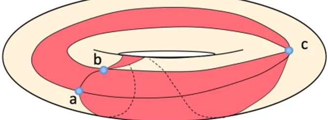
Figure 1: In the torus, at least three adjacent oriented facets (acb), (abc), and (cab) can share the three vertices a, b and c
Although the flip operation considered herein is not constrained by any geometrical criterion, care must be taken to ensure that the image of a triangulation T in T by a flip still belongs to T. Specifically, the flip of the edge (ab) will be forbidden whenever it would result in the creation of an edge connecting a vertex c to itself, i.e. when the two facets incident to (ab) are incident to the same three vertices a, b and c (see Figure 2). In the following, this edge (ab) is said to be unflippable. Similarly, the flip operation is meaningless for the boundary edges, which have only one incident facet; consequently, these edges are also unflippable.
e
e0
e
e0
Figure 2: Two examples of unflippable edges e
Note that our combinatorial class T is quite different from the one studied by Wagner [Wag36] and by Negami and Watanabe [NW90]. Indeed, we are working with triangulations where two different edges can share the same pair of vertices and, similarly, two different facets may share the same three vertices (Fig. 1 illustrates that it is even possible to have more than two facets in this situation when the genus of the surface is not 0). As a result, our framework does not imply a minimal number of vertices in the triangulations are considering. Moreover, if we work only on manifold oriented triangulations, the validity of the algorithms presented in this paper generalizes Wagner’s existence theorem to edge-flip sequences between higher-genus surfaces, while allowing further intermediate states of the evolving mesh.
2.2 Construction of an edge in a path of facets
Let a and b be two vertices of a triangulation T in T. T may contain constrained edges, in which flippling is forbidden. We analyse the conditions under which it is possible to exploit a simple path of facets that does not cross constrained edges between two vertices a and b, to install an edge (ab) by using edge flips. A path is determined from an exploration of the facets in the triangulation. When applicable, the method proposed constructs an edge (ab) whose relative position with respect to the existing constrained edges around a and b is the same as the position of the original path (see Figure 3). Note that our results imply that it is sometimes possible to establish a new edge (ab) between two vertices a and b that were already
connected by an edge. The two edges will be positioned differently in the topological disks around a and b.
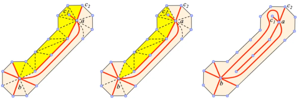
Figure 3: Given a simple path of facets that does not cross constrained edges (in red) between a and b, a sequence of edge flips in the path can here produce an edge (ab). The (ab) created has the same position as the initial path with respect to the constrained edges whose order has been preserved around a (resp. b). Here, the path starts in the piece of umbrella located between the constrained edges (ac1) and (ac2)
anti-clockwise, just like the resulting edge (ab). The same property is checked at the other end of the path.
2.2.1 Initial simplification of the path of facets
Let Finit = (f1, ..fq) be a simple, constraint-preserving path of facets between two vertices a and b
where each fiappears only once and the associated path of edges Einit= (e1, ..., eq−1) is composed of
unconstrained edges ei = fi∩ fi+1shared by fiand fi+1. Note that since it is possible for two adjacent
facets to share two edges, the path of edges is not necessarily unique. In order to obtain a simplified path, we remove the first facet and the first edge of the lists as long as the first edge is incident to a, and we remove the last facet and the last edge of the lists as long as the last edge is incident to b. Let F = (f1, f2, ..., fp) and E = (e1, ..., ep−1) be the resulting paths (see Figure 3). If E is empty, the edge
(ab) respecting the order of the constrained edges around a and b is already in T .
The envelope of a path of facets F is defined as the set of edges that are incident to a facet in F but that were not retained in the associated path of edges E. The connectivity of the edges on the envelope is deduced from the order and the connectivity of the facets in the path of facets.
2.2.2 Construction of (ab) from a simplified path of edges
The approach of recovering an edge (ab) by iteratively flipping the edges of a path between a and b is not new [VCP09], but we extend it to case containing unflippable edges. The cases where it is possible to use a simplified path of facets F and its associated path of edges E to establish an edge between a and b are the followings:
The case where a is incident to no facet but the first one (f1) in F : The edges of the path are flipped
incrementally from the first one to the last one to create the edge (ab). This operation is denoted as direct construction of(ab) inside F .
Proof. Indeed, e1 is not incident to a (since F is simplified) and e1 is flippable (otherwise f1 and f2
would be incident to the same three vertices including a, which is not possible). So Fe1(T ) generates an
edge that contains the vertex a, and two facets f10 and f20 that are necessarily located within the envelope of the original path of facets (see Figure 4). It is not restrictive to assume that f20 is the facet created incident to e2. Consequently, after the flip, a new path of facets F0 = (f20, ..., fi, ...fp) is obtained. F0
connects a and b and its length is reduced by one with respect to the initial path. Following the same reasoning, e2 is not incident to a and e2 is flippable since a is incident to f20 only. Therefore, the edge
(ab) can be constructed by flipping all the edges (e1, ..., ep−1) iteratively, and the resulting position of
a b e1 f1 f2 f3 f4 f5 f6 f7 e2 f20 f10 f3 e3 f30 f4 f10 f200 e4 f5 f40 e5 f6 f40 e6 f7 f60 a b
Figure 4: Construction of an edge (ab) from a path of facets in which a is incident to no facet but f1in F .
b
a
b
a
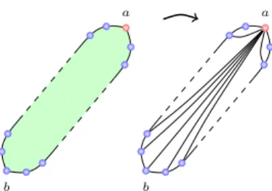
Figure 5: Abstract representation of the construction of (ab) in which no facet is incident to a but the first one (all the vertices in blue are different from a).
If b is incident to no facet but the last one (fp) in F , the result is symmetric, and the edge (ba) can
be constructed directly in reversed F by flipping all the edges (e1, ..., ep−1) in the reverse order.
The case where a is incident to several facets in F , but at least one edge of F is flippable: When a is incident to several facets in the simplified path F , the edges of E can be flipped iteratively as in the previous case, until an unflippable edge e is encountered: the lengh of the path of facets is decreased after each flip, and the path still remains simplified. It is therefore not restrictive to consider that e1is an
unflippable edge (i.e. f1 and f2share the same three vertices). e1 is not incident to a since the path is
simplified. b a vF fi ei b a vF
Figure 6: Abstract representation of the case where a is incident to several facets in F and eiis the first flippable edge in the path of edges
between a and b: in green, the subsequence of consecutive facets whose vertices are the same (a, a1and a2): in yellow, the other facets; in
pink, the facets that are removed from F . To provide of a clear illustration, the path of facets has been flattened, but one can still note that vertex a is involved in many facets.
Let us assume that the edge ei is the first flippable edge in E, which means that the i first facets
(f1, f2, .., fi) in the sequence F share the same three vertices as f1, and that the vertex vF opposite to
eiin fi+1is not a vertex of f1, f2, .., fi. Since vF is incident to no facet but the last one in the path F0
from a to vF, we can construct the edge (avF) directly in F0 as described in the previous case (flip of
the edges ei, ei−1, ..., e1successively). The resulting edge (avF) splits the envelope of the initial F into
two non-empty parts. Only one of them is a simplified path of facets between a and b (see Figure 6). The length of this new path is strictly reduced with respect to the original F .
We say in that case that F is reductible. The operation which consists in iteratively flipping the edges of E from the first one to the first unflippable one (not included), followed by the iterative flip of the edges (considered in the reverse order) from the first flippable one to the first edge of E, is denoted as a reduction of F .
Lemma 1: If a simplified path F between two vertices a and b is reducible to a path in which the extremity a is incident to only one facet in F , then it is possible to directly construct an edge (ab) in the envelope of F , by iteratively flipping the edges of the reduced path, oriented from a to b.
The case where none of the edges in E is flippable, which means that all the facets in F share the same three vertices a, b and c: The path of facets F cannot be reduced and cannot be used as is to construct an edge (ab) between its two ends. This means that it is not possible to create (ab) inside its envelope using edge flips. Nevertheless, there is a useful case where the path F can be used as a starting point for the construction of a new simplified and reducible path. This path has its length less than or equal to that of F , and it has the same relative position with regards to the constrained edges around a and b.
Turning anti-clockwise on the envelope of F , we denote as the right half-envelope the sequence of vertices between a and b, and the left half-envelope is the sequence of vertices between b and a.
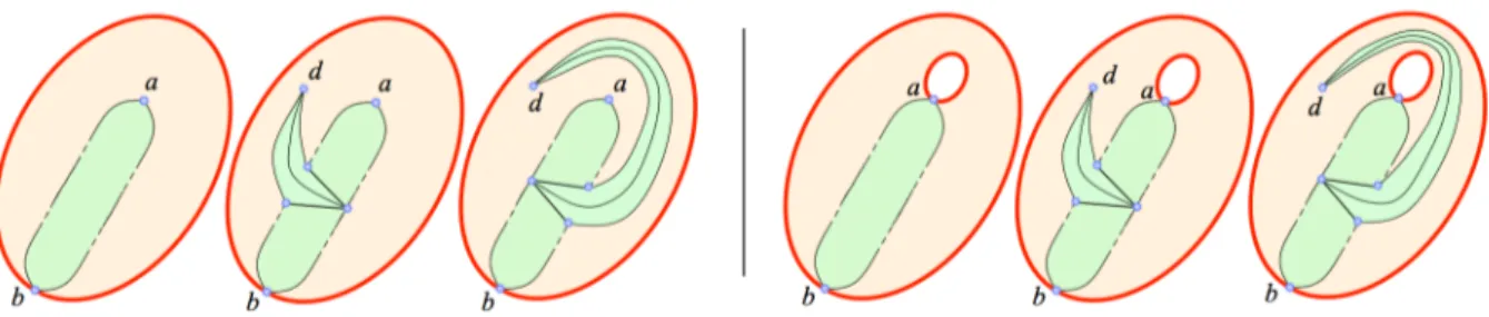
Lemma 2: Let F be a simplified path of facets between a and b that exclusively consists of facets incident to the same three vertices a, b and c. If one half-envelope of F contains at least one occurrence of c and it is possible to connect the remaining half-envelope to a vertex d different from a, b and c, without crossing any constrained edge, then F can be locally moved to a new path whose length is less than or equal to that of F , and whose envelope is not included in that of F .
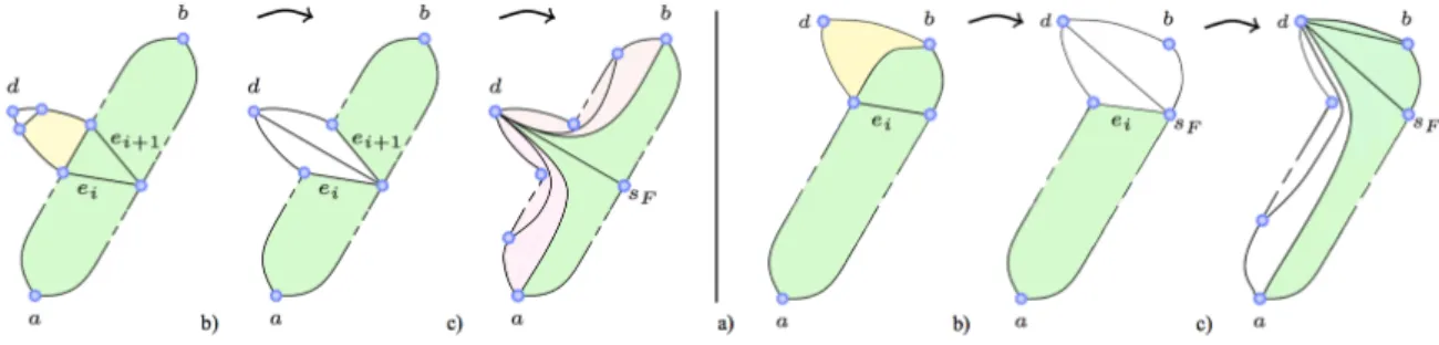
Figure 7: Abstract representation of the case in which the path F is composed of facets that are all incident to the same triplet of vertices a, b and c. If one half-envelope of F contains at least one occurence of c and the other half-envelope can be connected to a fourth vertex d, then F can be transformed into a shorter path (their length can also be equal) which is reducible: a) The path of facets between d and one edge of the half-envelope of F (in yelow) is enlarged with one facet of F , b) d is inserted in one half-envelope of the evolving F that is incremented by one facet, and the other half-envelope remains unchanged c) the construction of (ad) (or (db) if d has already been connected to a within the first facet of the path) reduces the length of the evolving path between a and b.
Proof. We first insert d into the corresponding half-envelope HEr, with the other half-envelope HEl
denoting the one with at least one occurence of c. To do so, we build a minimal path of facets between d and HEr and complete it with a facet of F (see Figure 7), obtaining a path F0 = (f10, ..fp00) between
a vertex sF in HEland d such that f10 is the only facet in F . Since d is incident to no facet but the last
one (fp00) in F0, we can directly construct the edge (sFd) inside F0. This inserts the edge (dsF) in the
associated path of facets E, and increments the number of facets in F by one. Note that d cannot be directly connected to both the origin and target vertices of the evolving F . Therefore, it is not restrictive to consider that d is not directly connected to the origin a of F . Then it is possible to directly construct an edge between d and the origin a of F , using lemma 1 above. The constructed edge (ad) splits F into two non-empty parts, and only one of them is a path of facets between a and b. This means that the length of the evolving F is now decreased by at least one facet. In the resulting path, the half-envelope that does not contain d has not been modified, so the resulting F is incident to the vertices a, b, c and d, and its length is less or equal to the length of the original F . There is a flippable edge in the remaining path of edges, i.e. it is possible to remove an additional facet in the path of facets derived from the original F .
In the particular case where HElis composed of only two edges (bc) and (ba), the vertex sF
The operation that consists in inserting a vertex d in a non-reducible path F in order to transform it into a reducible path is denoted a local move of the path.
This trick will be used in two particular cases that will be encountered in the algorithms presented in section 3.
Lemma 3: Let F be a simplified path of facets between a and b, with the associated path of edges E composed exclusively of unflippable edges. Let CF denote the connected component enclosing F (here
we consider the connectivity of facets across unconstrained edges). If CF encloses at least four different
vertices and if one half-envelope of F is composed of only two constrained edges (bc) and (ca) (we say that F is an umbrella path), then F can be locally moved to construct a shorter or equal reducible path of facets, whose first and last facets have the same position as the original F with regards to the constraints around a and b respectively. The resulting path is also an umbrella path.
Proof. This result is a direct consequence of lemma 2: the remaining half-envelope necessarily contains an unconstrained edge (otherwise the connected component CF would correspond to the interior of F ,
which is not possible, since it contains a fourth vertex different from a, b and c), that can be connected with a minimal path to a fourth vertex d (see Figure 8).
Figure 8: Case where the unreducible path F is an umbrella path inside a connected component with at least four vertices (constrained edges in red).
Lemma 4: Let F be a simplified path of facets between a and b, with the associated path of edges E exclusively composed of unflippable edges and each half-envelope of F containing at least one un-constrained edge. Let CF denote the connected component enclosing F . If CF encloses at least four
vertices and F does not split CF into two disconnected parts (the facets of F being excluded), then F
can be locally moved to construct a shorter or equally reducible path of facets, whose first and last facets have the same position as F with respect to the constraints around a and b respectively.
Proof. One of the two half-envelopes of F necessarily contains c and the result is another consequence of lemma 2: since CF is connected and touches the two half-envelopes at unconstrained edges, the fourth
vertex d can be connected to whatever half-envelope we need (see Figure 9).
Figure 9: Case where the path F between a and b is not reductible but is included in a connected component CF with at least four vertices
Now we illustrate that it is not always possible to use a path of facets between a and b to construct an edge (ab) by using the operations discussed above (simplification, reduction, local move and direct construction in a path).
Lemma 5: In some cases, there is no simple path of facets in the envelope of which it is possible to construct an edge.
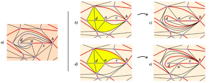
Proof. We have identified pathological cases where an edge (ab) cannot be built directly using a simple path of facets (see Figure 10). This does not mean that it is impossible to build the edge, but in this case, the prior creation of other edges, or, equivalently, the introduction of several occurrences of the same facet in the path may be necessary.
Figure 10: a) Triangulation T in which one wishes to construct a new edge (ab) between the constraint edges colored in red. For better visibility, T has been flattened on the plane, with the vertices a, b and c being duplicated; a) in yellow, the only direct path of facets available to construct the edge (ab)); b) there exists a triangulation of T featuring the desired edge (ab), but it cannot be constructed from the yellow path of facets (note that constructing (ab) is impossible without previously modifying the triangulation of T ).
3
Turning the connectivity of a triangulation into a target triangulation
Let there be Tinit and Ttarget in T, two oriented triangulations with the same vertices and sharing the
same topological genus and the same boundaries. Tinitand Ttarget may also contain constrained edges
that cannot be flipped. Any constrained edges have to be present in the two triangulations, they should have the same relative position around each vertex, and above all, the connected component they may delimit should be composed of the same interior vertices in the two triangulations and be bounded by the same boundaries. We then say that Tinit and Ttarget share a consistent set of constrained edges.
As far as the connected component are concerned, we recall that we consider the connectivity of facets exclusively across unconstrained edges. The aim of this task is to modify the connectivity of Tinit by
flipping a sequence of edges in order to recover the connectivity of Ttarget. Throughout the changes, the
evolving triangulation will be denoted Tcurrent, which is initialized to Tinit.
Figure 11: The two triangulations are different and share a similar boundary, but it is impossible to transfom one into the other by edge flipping, since all the facets are based on the same vertices a, b and c.
Lemma 6: One case in which it is not possible to turn Tinitinto Ttargetusing edge flipping (while
corre-sponding component in Tinit) contains only three vertices a, b and c and those vertices are connected
differently in the two triangulations (see Figure 11). This blocking situation can only be met when the connected component contains at least three facets. Within this limit, the triangulation of the connected component is unique in T, given its fixed boundary.
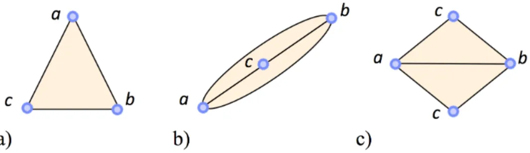
Proof. Indeed, the edges inside a connected component containing only three vertices are unflippable in the triangulation class T in which we are working. In the case where the connected component contains at most two facets, there are only three possible triangulations which are unique depending on the number of facets and the edges on the boundary (see Figure 12).
Figure 12: The only triangulations of T with only three vertices and at most two facets: a) one facet, three boundary edges, b) two facets, two boundary edges and one interior vertex, c) two facets, four boundary edges.
3.1 Hypothesis made on Ttarget
In order not to encounter a blocking situation in our algorithms turning one connectivity into another using edge flips, we will see that it suffices to assume that Ttarget does not enclose more than two
connected facets that share the same triplet of vertices, but we insist on the fact that this limit does not apply to Tinitor Tcurrent.
3.2 Strategy of iteratively integrating the edges of Ttarget into Tcurrent
We have shown that given a current triangulation Tcurrentin T, some edges can be incorporated into the
mesh using a path of facets under certain conditions. The connectivity of Tcurrent is only altered inside
the path of facets and its possible local moves are restrained inside the including connected component. However, the edges of Ttarget cannot be constructed into Tcurrent using an arbitrary order, since the
construction of an edge can interact with the construction of another edge. The naive algorithm consist-ing in iteratively constructconsist-ing the edges of Ttarget into Tcurrent may fail, introducing of an edge may
require the flip (hence the destruction) of other, previously built, edges. In order to avoid the possible problems of infinite loops, we have made it possible to block an edge, and we propose to use it to pre-serve each edge we construct. Whenever an edge of Ttarget is checked and constructed into Tcurrent, it
is blacklisted, meaning it becomes constrained and unusable in any path of edges involved in a future construction. Thus, at each step of the transformation, the triangulations Tcurrent and Ttarget are both
composed of a so called unexplored part which contains facets that are incident to at least one uncon-strained edge, and one conformed part, identical in the two meshes, which is exclusively composed of facets incident to constrained edges. Moreover, so that conforming an edge (ab) of Ttargetinto Tcurrent
does not prevent the future construction of edges present in Ttarget, the edge created (ab) must satisfy
the two following rules:
• The conforming (hence the blocking) of an edge that would split the unexplored region in the two meshes is forbidden whenever it would separate vertices of Tcurrent that are adjacent in Ttarget
helps ensure the further existence of a path of facets between vertices of Tcurrentthat are adjacent
in Ttarget.
• The conforming (hence the blocking) of an edge (ab) must respect of the order of constrained edges around the extremities a and b in Ttarget (which is ensured if the path of facets used to
construct the edge respects this order). Moreover, whenever conforming and blocking an edge splits the unexplored region, we must check that the resulting cycles of constrained edges are oriented consistently in Tcurrentand Ttarget(see Figure 14). Otherwise, the proposed construction
of (ab) is cancelled. This second constraint ensures that the conformed facets resulting from the conforming of the edges have a similar orientation in Tcurrentand Ttarget. In combination with the
previous rule, it also ensures the further existence of a path of facets between vertices of Tcurrent
that are adjacent in Ttarget.
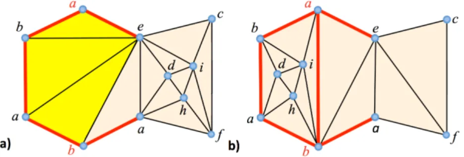
Figure 13: a) Ttargetfeaturing an edge (ab) and constraint edges in red; b) Tcurrentfeaturing a simplified path between a and b (in yellow);
c) the construction of the edge (ab) using the path would split the including connected component into two parts and separate c and d whereas they are connected in Ttarget; d) another admissible path between a and b in Tcurrent(in yellow) e) to construct a valid edge (ab) (c and d
are no longer separated).
Figure 14: a) Ttargetfeaturing an edge (ab) in blue and constrained edges in red; b) Tcurrentfeaturing a simplified path between a and b
(in yellow); c) the construction of (ab) in Tcurrentrespects the first rule but results in a cycle with a false orientation (note also that there is
no longer a path between c and d which are connected in Ttargetand respect the order of constrained edges around c); d) another simplified
path between a and b in Tcurrent(in yellow); e) admissible construction of (ab) in Tcurrent.
At the beginning of the algorithm, the two triangulations share a consistent set of constrained edges. If the two rules introduced above are checked at each attempt to conform an edge, the evolving set of
constrained edges is ensured to remain consistent. Note that the satisfiability of the two rules mainly depends on the path of facets used to conform the edge. However, it is not always possible to construct a path of facets from which the construction of an edge is possible while satisfying the two rules (see Figure 10).
3.3 Generic algorithm for connectivity conformation
We denote as directly constructible an edge e of Ttarget for which one has found a path of facets in
Tcurrentthat can be used to construct e by edge flips (in combination with local path moves if necessary,
as presented in 2.2.2), while respecting the two rules presented in the previous subsection 3.2. We now present a general algorithm to conform the connectivity of two triangulations Tinit and Ttarget in T
sharing a consistent set of constrained edges and boundaries, with no more than two connected facets incident to a same triplet of vertices in Ttarget. This algorithm is founded on the property that at each
step, there exists at least one directly constructible edge. The path used to check whether an edge e is directly constructible or not is the path of facets is as direct as possible whose position is similar to the one of e in Ttargetposition with respect to constrained edges around the extremities of e. Recall that this
path of facets should also not cross any constrained edge (a breadth-first exploration of the mesh can be used for this task). This path is first simplified if necessary, as described in 2.2.1.
3.3.1 Algorithm
The generic algorithm conforming the edges of Ttargetinto Tcurrentproceeds as follows:
Algorithm 1 Turn the connectivity of Tcurrentinto the connectivity of Ttarget
while Ttarget contains unconstrained edges that do not belong to Tcurrentdo
find a directly constructible edge e in Ttarget that does not belong to Tcurrent
construct e in Tcurrent
block e end while
3.3.2 Proof of the generic algorithm
We have already explained how a path of facets can sometimes be used to construct an edge (ab) (details in 2.2). In this case, the constructed edge complies with the position of the path with respect to the constrained edges around a and b, even when local moves of the path are implied. Let us recall that a local move of the path is performed only when no edge of the path is flippable, but it is not always possible to resort to it. If the path cannot be used to construct the edge (ab) and no path move is possible, the edge is not directly constructible. In the same way, if the edge (ab) can be constructed but does not respect one of the two rules in 3.2, it is cancelled and considered as not directly constructible. Therefore, all unconstrained edges in Ttargetare not directly constructible at each step of the algorithm.
Proof. To demonstrate that the general algorithm converges, it suffices to prove that at each step there exists at least one directly constructible edge:
• If there is a cyclical path of facets in Ttarget (that does not cross any constrained edge), then
every edge (ab) of Ttarget involved in the corresponding edge path is directly constructible (see
Figures 15 and 16). Indeed, the construction and the blocking of (ab) does not imply the split of an unexplored connected component in the two meshes, which means that the two rules of 3.2 should be respected if an admissible path is found. Therefore, we must ensure that the construction of (ab) is possible even in the particular case where all the edges of the simplified path F between a
vertices a, b and c), because of the path’s local moves. Indeed, local moves are performed by inserting a fourth vertex d in the half-envelope of the path that requires it. This fourth vertex d can always be found in the connected component enclosing the path F : the connectivity inside the component differs in Tcurrentand Ttargetotherwise the edge (ab) would already exist in Tcurrent
and there would be no problem to create it. This means that the connected component contains at least three facets but there can be no more than two connected facets sharing the same vertices in Ttarget (note that the connected component we are working with is also the connected component
containing the cyclical path of facets in Ttarget). Any half-envelope of the path F can be connected
to d since none of them can be exclusively composed of constrained edges and the path F does not split the including connected component. Therefore, Lemma 4 ensures that F can be locally moved into a reducible path. Whenever this particular case is met, the insertion of vertices in the envelope is performed as many times as necessary to create flippable edges and to decrease the length of the path, until creation of the desired edge (ab).
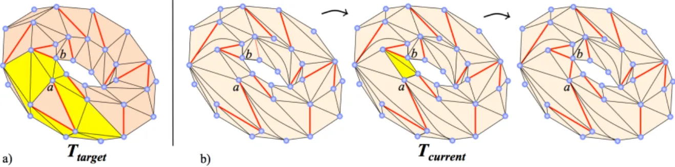
Figure 15: a) Cyclical path of facets (in yellow) around one vertex a in Ttarget(constrained edges in red); b) The conforming of (ab) into
Tcurrentis always possible (path of facets used in yellow).
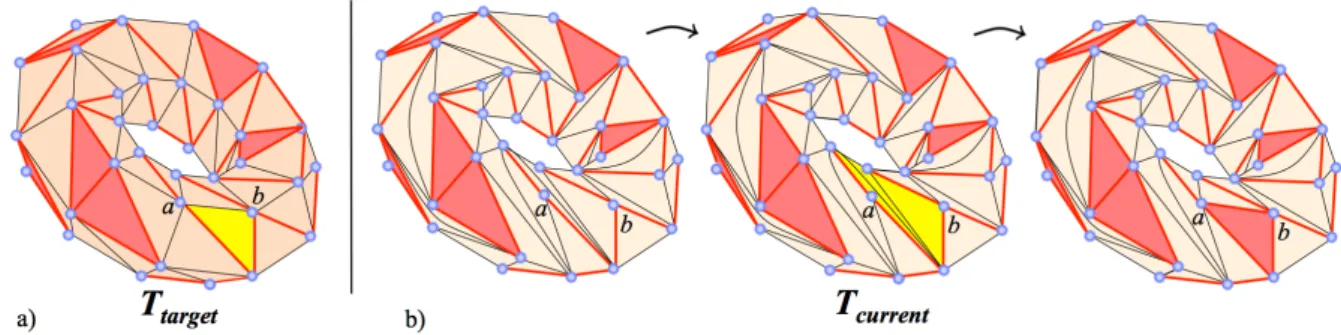
Figure 16: a) Cyclical path of facets (in yellow) in Ttargetand (ab) an edge of the associated edge path (constrained edges in red); b)
conforming of (ab) into Tcurrent(path of facets used in yellow).
• Let us show that a directly constructible edge still exists, even when no cyclical path of facets exists in Ttarget (this implies that all the vertices of Tcurrent and Ttarget are incident to a constrained
edge). By constructing an edge of Ttargetin Tcurrent, a connected component will necessarily be
split. Therefore, each connected component corresponds to a tree for the unconstrained adjacency relation between the facets in Ttarget. If all the trees are composed of one node, Tcurrent and
Ttargetare identical and the algorithm is over. Otherwise, let us consider one leaf a a tree that is not
reduced to a single node. It corresponds to an oriented facet (abc) of Ttargetthat is bounded by two
constrained edges (ca) and (cb). The edge (ab) that closes the facet (abc) is directly constructible in Tcurrent(see Figure 17): indeed, a path of facets to build (ab) while being compatible with rule
2 in 3.2 is contained in the oriented piece of umbrella around c between (ca) and (cb) in Tcurrent,
and a breadth-first traversal from a can be used to exhibit this umbrella path. We must also ensure that the construction of (ab) is possible even in the particular case where all of the path’s edges between a and b are unflippable (all the facets of the path have the same vertices a, b and c), because of the local moves of the path that can be performed in these conditions (Lemma 3). This
occurs in the case where one of the two half-envelopes of the path is composed of the constrained edges (cb) and (ca). A fourth vertex d can always be found in the connected component in which the path is enclosed (no more than two connected facets sharing the same vertices in Ttarget), and
the remaining half-envelope of the path can be connected to d. The vertices are inserted in the half-envelope as many times as necessary to create a flippable edge and to decrease the length of the path. Rule 1 is respected since the connected component created contains no interior vertex.
Figure 17: Ttargetcontains no more cyclical path of facets (constrained edges in red); a) The edge ab that closes the oriented facet (abc) with
the constrained edges (ca) and (cb) in Ttargetis directly constructible; b) conforming (ab) into Tcurrent(path of facets used in yellow).
Of course, the overall complexity of this algorithm depends considerably on the complexities of the path determination and constructability tests. In particular, if the construction of an edge adds a con-nected component to the mesh, verifying the correctness of this new component can be highly complex. In the next section, we propose an efficient strategy that consists in only splitting the unexplored region by closing a single facet, in order to significantly reduce the number of tests. This amounts to building the connectivity facet by facet.
3.4 An efficient facet-based instantiation of the algorithm
We now present a particular instantiation of the above-described algorithm, in which the closure of a cycle of constrained edges always closes a single facet : the cost of the constructability test becomes constant (excluding the cost of the simulation of the edge construction) or even null if we slightly mod-ify the strategy for the edge construction. In fact, the construction of the edges is reduced to three different cases, which we explain in the context of this new algorithm. This efficient algorithm consists in iteratively constructing oriented facets, instead of only edges. Moreover, we propose to proceed to conforming the facets by region growing on Ttargetin order to avoid ordering the blocked edges around
each vertex. Region growing is initiated from a facet of Ttargetthat is first constructed into Tcurrent. As
it evolves, the Tcurrent triangulation is composed of two areas: the conformed region Rc, consisting of
facets of Ttarget already built into Tcurrent (blocked), and the unexplored region Ru, consisting of the
other facets.
3.5 Region-growing strategy
Given a first constructed facet in Tcurrent, we want our region-growing strategy to guarantee that the
unexplored region Ruconsists of a single connected component. This ensures the existence of a path of
facets between two arbitrary vertices u1and u2in Ru. This also requires that the construction of a facet
3.5.1 Facet closure (FC):
If two edges (ac) and (ab) are constrained, (abc) is constructed in two steps (see figure 18). We first determine in Tcurrentthe unique path of facets F = (f1, f2, ..., fi, ..., fp) joining b and c in the oriented
umbrella of facets incident to a. We then construct the edge (bc) in the path of facets F as described in 2.2, while possibly using local path moves, in case all the edges are unflippable (a possibility ensured by Lemma 3). a b c Rc Ru a b c Rc Ru
Figure 18: Constructing the facet (abc) in the case (F C)
3.5.2 Creation of a facet towards a new vertex (NV):
If only one edge (ab) of (abc) is constrained and the vertex c is not incident to any constrained edge, then the facet (abc) can be built (see Figure 19). The edge (ac) is constructed using the algorithm described in section 2.2 with the shortest path of facets joining (ab) to c (the construction inside the path is then direct since c is incident to no facet of the path but the last one, which means that no local path move is required). Afterwards, the edge (bc) is constructed as in the previous case (F C).
a b c Rc Ru a b c Rc Ru a b c Rc Ru
Figure 19: Constructing the facet (abc) in (N V )
3.5.3 Creation of a facet towards a previous vertex (PV):
If only one edge (ab) of (abc) is constrained and the vertex c is already incident to a constrained edge, the construction of (abc) is allowed in the only case where the resulting facet does not split Ru into
two connected components (see Figure 20). The edge (ac) is constructed using the algorithm described in section 2.2 with the shortest path of facets joining (ab) to c, while possibly using local path moves, in case all the edges are unflippable (a possibility ensured by Lemma 4). Afterwards, the edge (bc) is constructed as in the previous case (F C) .
Note that (PV) is performed in particular when both (N V ) and (F C) can be applied nowhere in Ru
(and Rucontains more than one facet). Ruthen corresponds to the cycle of facets that can be exhibited
by running along the border of Ru. The construction of one facet (abc) belonging to the cycle will not
split Ruinto two connected components.
It is clear that the time complexity of a facet construction differs graetly from one case to another. The (F C) case can be executed in constant time on average, but O(n) in the worst-case scenario (n being the number of vertices). The construction costs are O(n) on average in the (N V ) and (P V ) cases, but may reach O(n2) in the worst case. Therefore, the overall algorithm has a complexity O(n3) in the worst-case scenario, but the experimental results shown in section 4 exhibit a linear statistical complexity.
a b c Ru Rc a b c Ru Rc
Figure 20: Constructing the facet (abc) in the case (P V )
It is worthwhile to noting that regarding the orientations of the facets created, it is only necessary to check the first facet. The orientation depends on how the third edge (bc) is constructed, and more specifically, on the facet path considered to connect b and c. This path is built into the umbrella of facets incident to a, which leaves only one possibility when a is already incident to a blocked facet, so that, the orientation of the facet (abc) is always consistent with the facets previously built.
3.6 Constructing the first well-oriented facet
Flip operations applied to Tcurrentmust be chosen so that the facets of the triangulation obtained at the
end of the algorithm are the same as the facets of Ttarget, even in terms of orientation. Therefore, care
must be taken to conform the first oriented facet (abc) into Tcurrent (see Figure 21). When closing the
first facet (abc) after creation of the edges (ab) and (ac) (using (N V )), it is not always obvious to know the right orientation of the umbrella of a in Tcurrent, when a is not a boundary vertex. Therefore, the
edge (bc) is constructed as described in (F C), while possibly trying the two options for the orientation of the umbrella around a in Tcurrent. Among these two configurations, the algorithm must choose the
one that corresponds to a correct orientation of the resulting facet.
b c a 1st step b c a 2nd step b c a 3rd step, 1st try b c a 2nd step b c a 3rd step, 2nd try
Figure 21: Constructing the first well-oriented facet (abc).
3.7 Algorithm
The algorithm to conform the connectivity of Ttargetinto Tcurrentis now simple to write (see Algo. 2).
It should be noted that the three cases do not address the construction of a facet with all of its edges constrained. This case occurs when the region Ruis reduced to a single facet, that is at the end of the
algorithm. Since in Tcurrentand Ttarget, this last facet is incident to the same vertices and has the same
orientation (by the orientation consistency discussed above), it is identical in the two triangulations. This explains why the last facet is treated separately. When all the facets of Ttargetare built, the algorithm is
over and the triangulations Tcurrentand Ttarget are identical.
Algorithm 2 Algorithm to conform the connectivity of Ttargetinto Tcurrent
Build the first facet (with the correct orientation) while at least two facets remain to be built do
while there is a facet corresponding to (N V ) or (F C) do Build the facet
Block its edges end while
if facets remain to be built then Build a facet verifying (P V ) Block its edges
end if end while
Build the last facet
begins with several oriented facets seeds. Indeed, the region Rumust be imperatively limited to a single
connected component, but the method imposes no constraint on Rc.
3.8 Proof of the algorithm
The region-growing algorithm can be proved by showing it is a particular case of the generic algorithm, but we prefer to present an alternate demonstration that we find to be more elegant.
To show that the current triangulation Tcurrent converges toward the target triangulation Ttarget, we
begin by recalling that at each step of the algorithm, the triangulation Tcurrent is always composed of
two regions Rc(the conformed region) and Ru (the unexplored region). With the three operations
in-volved, Rualways remains a connected component. By maintaining the connectivity of Ru, we ensure
that the algorithm can always find a path of facets between the two extremities of an edge of Ttarget.
Let us show that the region growing using the operations described in (NV), (FC) and (PV) can conform and block all the target facets in Tcurrent. We recall that if Rcis not empty then Ruis a surface with a
boundary.
Theorem A.1. If an expansion (region growing restrained to the operations described in (N V ) and (F C)) does not reduce Ruto a single oriented facet, then Ruis not contractible.
Proof. Suppose that Ru is not reduced to a single facet after the expansion and is contractible. Let B
be the set of unexplored facets of Ttarget that are incident to at least one edge of the Rcboundary. The
facets of B have their three vertices belonging to this boundary, otherwise they should have been built by the expansion from (NV) and inserted in Rc. As the unexplored area Ruis contractible, all the triangles
corresponding to the facets of B are included in a triangular tiling of the n-gon whose vertices are those of the boundary of Rc. Note that two triangles of B that geometrically share an edge in the tiling do not
necessarily correspond to adjacent facets in the triangulation Ttarget(see Figure 22). However, since all
the triangulations of an n-gon have at least one triangle t incident to two edges of the boundary, and the triangles of the tiling that are incident to an edge of the boundary correspond to a facet of B, the facet of B corresponding to t is then is in the configuration of the (FC) case and should have been inserted into Rc, which is contrary to the hypothesis.
Theorem A.2. At the end of the conforming algorithm, the connectivity of Tcurrentand Ttarget are
the same.
Proof. Let us show that as long as oriented facets of Ttarget remain that are not in Tcurrent, it is always
possible to construct another oriented facet by using one of the three cases of the algorithm. Suppose that the expansion ((NV) and (FC) only) does not reduce Ru to a single oriented facet. According to
not homotopic to a point in Ru. The edges of the boundary between Rc and Ru form a closed curve
without multiple points, and we construct a sequence of triangles with the facets of Ru incident to this
curve enclosing the existing cycles. The sequence is a cyclic path of facets, with possibly some facets present several times in the sequence, so that it is possible to extract one or several simple cyclic path of facets from it (any facet appears only once in this a simple facet path) that are maximal by construction. Consequently, there is at least one simple cyclic path of facets, which contains at least one facet with one edge on the boundary between Rcand Ru (and its three vertices on the boundary as described above:
otherwise (N V ) could have been performed). This facet can be inserted into Tcurrent by the operation
corresponding to (PV), because it will not split the connected component Ru. From these observations,
we deduce that it is always possible to conform a new facet of Ttarget into Tcurrent, because after an
expansion scheme, there is either only one facet remaining to be built, meaning that the determination is complete, or several facets remain, and we can conform a new facet using (PV). Consequently, at the end of the algorithm, all facets of Ttargetwill be constructed in Tcurrentand the two triangulations have
the same number of vertices and the same topological genus.
In fact, the expansion steps ((N V ) and (F C) only) can be seen as a process that grows Rcwithout
changing its Euler characteristic. On the other hand, this characteristic decreases by one each time we conform a facet using (P V ). Therefore, if the Euler characteristic of Rcis equal to the Euler
character-istic of Ttarget deprived of one facet, all facets of Ttarget can be constructed in Tcurrentusing a single
expansion.
Corollary 3.1. Let g be the genus of an oriented surface and b the number of disjoint closed bound-aries. The algorithm uses the case (P V ) 2g + b times.
Proof. After the construction of the first facet, the Euler characteristic of Rcis equal to 1. The expansion
does not change the Euler characteristic, but the (P V ) case decreases the characteristic of Rc. As the
Euler characteristic of Ttargetdeprived of one facet is equal to 2 − 2g − (b + 1), (P V ) will be applied
2g + b times.
Note that the (N V ) and (F C) cases are sufficient when the genus of Tinitand Ttargetis 0.
We draw the reader’s attention to the fact that the geometry of the triangulation is never used by the algorithm. Indeed, the geometries of triangulations Tinitand Ttargetcan be different.
Let us note also that the algorithm can be parallelized. The principle is to start the algorithm using several seeds and independently manage the expansion of each growing region Rc. The only important
property is that the unexplored region is still composed of a single connected component.
The cycles encountered after each expansion step are similar to the loops extracted by Lazarus et al [LPVV01] on a triangulated surface, such that cutting the surface along these loops yields a polygon schema. Indeed, their algorithm also involves a region-growing algorithm driven by operations similar to (N V ), (F C) and (P V ). Ru Rc a) Ru Rc b)
Figure 22: Tiling of the n-gon corresponding to the boundary between unexplored and conformed regions: a) The unexplored region is assumed to be contractible; b) Triangular tiling including the facets incident to the boundary edges.
Sphere Bimba Torus Genus 3
Sphere Bimba Torus Genus 3
+295 027 flips∗ +1 310 662 flips∗ +361 805 flips∗ +1 071 847 flips∗
Genus 0 0 1 3
Vertices 21 872 192 135 12 150 179 708 Edges 65 610 576 399 36 450 539 136
Tinit Sphere Bimba Torus Genus 3
Ttarget Sphere Bimba Torus Genus 3
Flips 0 0 0 0
Times (ms) 220 3 012 138 2 400
Tinit Sphere Bimba Torus Genus 3
Ttarget Sphere Bimba Torus Genus 3
+295 027 flips∗ +1 310 662 flips∗ +361 805 flips∗ +1 071 847 flips∗
Flips 114 417 645 970 125 148 492 386
Times (ms) 916 9 110 995 9 539
Table 1: Experimental results
4
Experimental results
The experiments in Table 1 were conducted on a PC with an Intel Core 2 Duo 3GHz CPU and 4 Gb of RAM. The triangulations with∗ are randomly generated with a massive amount of consecutive flips such that an edge is never flipped again as long as its two adjacent facets do not change.
Figure 23: The algorithm applied to a triangulation of a genus 1 surface
Note that our algorithm cannot be compared to an existing one in any situation, since our class of triangulations T is wider than the one usually considered, which allows more configurations of the intermediate triangulations. We have compared this in the particular case of geometric planar triangu-lations. To turn one planar triangulation into another, it is possible to use an algorithm using geometric edge flips [Law77], in which the Delaunay configuration is an intermediate canonical configuration. We compare it to our algorithm on an example (see Figure 24) which does not contain cocycle vertices.
Figure 24: Running algorithm between Tinitand Ttarget: a) Using a Delaunay triangulation as a pivot; we obtain 353 geometric flips, b)
Our algorithm; we obtain 294 combinatorial flips.
5
Conclusion and perspectives
We have presented a general and original algorithm to determine a sequence of edge flips between two oriented, triangulated surfaces, with the same number of vertices and topological genus. The facet-based version of this algorithm, easy to implement, is a useful tool for manipulating the connectivity of a mesh. Unlike the existing results based on the topological genus of the underlying surface, our algorithm requires no prior knowledge on the surface, does not involve the geometry of the mesh and does not make use of a canonical connectivity configuration between the initial and target triangulations. This makes it possible to obtain very short sequences of edge flips for relatively undisturbed meshes (or no flips at all if the triangulations are the same), which is a valuable property for compression purposes. However, it could be useful to generalize the determination algorithm so that it can be applied to nonorientable triangulated surfaces, or to extend the class of triangulations considered in order to allow more flip operations. In addition to widening the scope of the current method, this would give more flexibility to compute the flip sequences between two manifold triangulations, because the combinatory of the sequences would be increased and could therefore satisfy more constraints.
This paper has focused on edge flips, but we could combine these results with other operations. This would result in the proposition of a new algorithm for determining bistellar moves between two triangulations of the same compact manifold coinciding on their boundaries. It would initially insert or remove vertices in Tcurrentso that the two triangulations have the same number of vertices and the same
References
[ABR06] ALBOULL., BRINK W., RODRIGUESM.: Mesh optimisation based on willmore energy. 22nd European Workshop on Computational Geometry(2006), 133–136.
[ADLRS10] A. DELOERAJ., RAMBAUJ., SANTOSF.: Triangulations: Structures for Algorithms and Applications. Algorithms and Computation in Mathematics. Springer, Novembre 2010.
[AG05] ALLIEZP., GOTSMANC.: Recent Advances in Compression of 3D Meshes. Advances in
Multiresolution for Geometric Modelling(2005), 3–26.
[BH09] BOSEP., HURTADOF.: Flips in planar graphs. Comput. Geom. Theory Appl. 42 (January 2009), 60–80.
[Dew73] DEWDNEYA.: Wagner’s theorem for torus graphs. Discrete Mathematics 4 (Feb. 1973), 139–149.
[DZM07] DYERR., ZHANG H., M ¨OLLER T.: Delaunay mesh construction. In Proceedings of the fifth Eurographics symposium on Geometry processing(2007), pp. 273–282.
[ES96] EDELSBRUNNER H., SHAH N. R.: Incremental topological flipping works for regular
triangulations. Algorithmica 15 (1996), 223–241. 10.1007/BF01975867.
[HOS96] HANKES., OTTMANN T., SCHUIERERS.: The edge-flipping distance of triangulations. j-jucs 2, 8 (1996), 570–579.
[Law72] LAWSON C. L.: Transforming Triangulations. Discrete Mathematics 3, 4 (1972), 365– 372.
[Law77] LAWSONC. L.: Software for c1surface interpolation. Mathematical Software III (1977), 161–194.
[LL00] LEIBONG., LETSCHERD.: Delaunay triangulations and voronoi diagrams for riemannian manifolds. In Proceedings of the sixteenth annual symposium on Computational geometry (New York, NY, USA, 2000), SCG ’00, ACM, pp. 341–349.
[LPVV01] LAZARUS F., POCCHIOLA M., VEGTER G., VERROUST A.: Computing a canonical
polygonal schema of an orientable triangulated surface. In Proceedings of the seventeenth annual symposium on Computational geometry(2001), SCG ’01, pp. 80–89.
[Neg99] NEGAMIS.: Diagonal transformations of triangulations on surfaces, a survey. Yokohama Mathematical Journal 47(1999), 1–40.
[NW90] NEGAMI S., WATANABE S.: Diagonal transformations of triangulations on surfaces.
Tsukuba journal of mathematics 14(1990), 155–166.
[Pac91] PACHNER U.: P.l. homeomorphic manifolds are equivalent by elementary shellings. Eu-ropean Journal of Combinatorics 12(1991), 129–8145.
[VCP09] VALETTE S., CHAINE R., PROST R.: Progressive lossless mesh compression via incre-mental parametric refinement. In Proceedings of the Symposium on Geometry Process-ing(Aire-la-Ville, Switzerland, Switzerland, 2009), SGP ’09, Eurographics Association, pp. 1301–1310.
[Wag36] WAGNERK.: Bemekungen zum vierfarbenproblem. Jahresber. Deutsch. Math.-Verein. 46 (1936), 26–32.