UNIVERS rTÉ DE
SHERBROOKE
Faculté de génieDépartement de génie civil
SERVICEABILITY OF CONCRETE MEMBERS
REINFORCED WITH FRP BARS
ÉTUDE DU COMPORTEMENT EN SERVICE DE
MEMBRURES EN BÉTON RENFORCÉES DE BARRES
DE PRF
Thèse de doctorat Spécialité : génie civil
Jury: Prof. Brahim BENM OKRANE, directeur de recherche Prof. Amr ELRAGABY, Examinateur
Prof. Adel EL SAFTY, Examinateur Prof. Ammar YAHIA, Rapporteur
Amr Maher EI-Nemr
1+1
Library and Archives Canada Published Heritage Branch Bibliothèque et Archives Canada Direction du Patrimoine de l'édition 395 Wellington Street Ottawa ON K 1A0N 4 Canada 395, rue Wellington Ottawa ON K1A 0N4 CanadaYour file Votre référence IS B N : 978-0-494 -93 23 0-8 O ur file N otre référe nce IS B N : 978-0-494 -93 23 0-8
NOTICE:
The author has granted a non
exclusive license allowing Library and Archives Canada to reproduce, publish, archive, preserve, conserve, communicate to the public by
telecomm unication or on the Internet, loan, distrbute and sell theses
worldwide, for commercial or non commercial purposes, in microform, paper, electronic and/or any other formats.
AVIS:
L'auteur a accordé une licence non exclusive permettant à la Bibliothèque et Archives Canada de reproduire, publier, archiver, sauvegarder, conserver, transmettre au public par télécomm unication ou par l'Internet, prêter, distribuer et vendre des thèses partout dans le monde, à des fins com merciales ou autres, sur support microforme, papier, électronique et/ou autres formats.
The author retains copyright ownership and moral rights in this thesis. Neither the thesis nor substantial extracts from it may be printed or otherwise reproduced without the author's permission.
L'auteur conserve la propriété du droit d'auteur et des droits moraux qui protege cette thèse. Ni la thèse ni des extraits substantiels de celle-ci ne doivent être imprimés ou autrement
reproduits sans son autorisation.
In compliance with the Canadian Privacy A ct some supporting forms may have been removed from this thesis.
W hile these forms may be included in the document page count, their removal does not represent any loss of content from the thesis.
Conform ém ent à la loi canadienne sur la protection de la vie privée, quelques
form ulaires secondaires ont été enlevés de cette thèse.
Bien que ces form ulaires aient inclus dans la pagination, il n'y aura aucun contenu manquant.
A b str a c t
ABSTRACT
The deterioration of Canadian infrastructure due to corrosion of steel reinforcement is one of the major challenges facing the construction industry. Recent advances in polymer technology have led to the development o f new generations of fiber-reinforced-polymer (FRP) reinforcing bars. These corrosion resistant bars have shown promise way to further protect bridges and public infrastructure from the devastating effects o f corrosion. The recently published [CAN/CSA-S807, 2010] “Specification fo r fibre-reinforced Polymers" along with the FRP bars being produced of the highest quality strongly supported the FRP reinforcement as a realistic and cost-effective alternative to traditional steel reinforcement for concrete structures under severe environmental conditions.
The design of concrete members reinforced with FRP bars is typically governed by serviceability state rather than ultimate state. Thus, there is a need to investigate the flexural performance and the deflection and crack width behaviour, the two terms of serviceability criteria. In addition, recent developments in the FRP industry led to introducing FRP bars with different surface configurations and mechanical properties as well. These developments are expected to affect their bond performance and, consequently, the crack width in FRP- reinforced concrete members. The design codes and guidelines, however, provide a unique value for the bond-dependent coefficient (kb) considering the surface configurations and neglecting FRP bar type, bar diameter, and concrete type and strength.
This research program aims at investigating the flexural behaviour and serviceability performance of concrete members reinforced with different types and ratios o f carbon and glass FRP bars and fabricated using normal-and high-strength concretes. In addition, it evaluates the bond-dependent coefficient (kb) o f glass and carbon FRP bars in normal- and
A b str a c t
high-strength concrete beams. The experimental program included fabricating and testing of thirty three full-scale simply-supported beams measuring 4250-mm long x 200-mm wide x 400-mm deep. Twenty seven concrete beams were reinforced with glass FRP bars, four concrete beams were reinforced with carbon FRP bars, and two beams were reinforced with steel bars. All beams were tested in four-point bending over a clear span of 3750 mm. The test parameters were: reinforcement type and ratio, FRP bar diameter and surface configurations, number of FRP layers, and concrete strength. The test results of these beams were presented and discussed in terms of flexural capacity and mode of failure, concrete and reinforcement strains, deflection, and crack widths through three journal papers presented in this thesis.
Among the three papers presented in this thesis, two investigated the flexural behaviour and serviceability performance of carbon and glass FRP-reinforced concrete beams fabricated with normal- and high-strength concretes. These two papers investigated GFRP bars o f different grades, diameters, and surface configurations. While the third one evaluated the current design recommendations for bond-dependent coefficient (fa) values and checked the dependency of the kb values on FRP bar type (glass and carbon), diameter, and concrete type and strength. The cracking moments and flexural capacity were compared against the provisions of the North American codes and guidelines [ACI 440.1R-06, 2006; ISIS Manual No.3, 2007; CAN/CSA-S6.1S1, 2010; CAN/CSA-S806, 2012], In addition, the experimental results were employed in assessing the accuracy o f the current deflection and crack-width prediction equations and the fa values in the FRP design codes and guidelines in North America [ACI 440.1R-06, 2006; ISIS Manual No.3, 2007; CAN/CSA-S6.1S1, 2010; CAN/CSA-S806, 2012]. The results introduced the effect of different parameters on the flexural behaviour and serviceability performance o f the FRP- reinforced concrete members.
A b str a c t
Furthermore, the findings did not support the unique kb value for FRP bars o f different types (carbon and glass) with similar surface configurations and was found to be dependent on bar diameter.
R ésu m é
RÉSUMÉ
La détérioration des infrastructures au Canada due à la corrosion des armatures est l'un des défis majeurs de l'industrie de la construction. Les progrès récents dans la technologie des polymères ont conduit au développement d ’une nouvelle génération de barres d'armature à base de fibres renforcées de polymères (PRF), (en particulier les fibres de verre). Ces barres, résistant à la corrosion, ont montré un grand potentiel d ’utilisation pour mieux protéger les infrastructures en béton armé contre les effets dévastateurs de la corrosion. Avec la publication du nouveau code S807-10 "Spécifications pour les polymères renforcés de fibres" et la production de barres en PRF de très haute qualité, celles-ci représentent une alternative réaliste et rentable par rapport à l’armature en acier pour les structures en béton soumises à de sévères conditions environnementales.
La conception des éléments en béton armé de barres en PRF est généralement gouvernée par l'état de service plutôt que l'état ultime. Par conséquent, il est nécessaire d'analyser les performances en flexion et le comportement en service en termes de déflexion et de largeur de fissures des éléments en PRF sous charges de service et de vérifier que ces éléments rencontrent les limites des codes.
Aussi, de récents développements dans l'industrie des PRF ont conduit à l'introduction des barres en PRF avec des configurations de surface et des propriétés mécaniques différentes. Ces développements sont susceptibles d'affecter leur performance d ’adhérence et, par conséquent, la largeur des fissures dans les éléments en PRF. Cependant, les codes de conception et les guidelines de calcul fournissent une valeur unique pour le coefficient
R ésum é
d'adhérence (kb) en tenant compte des configurations de surface et en négligeant le type de barre en PRF, le diamètre de la barre, et le type de béton et de sa résistance.
En outre, le code canadien S807-10 "Spécifications pour les polymères renforcés de
fibres" fournit une étape en classant les barres en PRF par rapport à leur module d ’élasticité (E/rp). Ces classifications ont été divisées en trois classes : Classe I (E/rp <50 GPa), Classe II
(50 GPa < Efrp < 60 GPa) et Classe III (Ejrp > 60 GPa)
Ce programme de recherche vise à étudier expérimentalement le com portement en flexion des éléments en béton en service armé avec différents paramètres sous charges statiques. Le programme expérimental est basé sous plusieurs paramètres, dont les différents ratios de renforcement, différents types de barres (différentes classes comme classifiées par le CAN/CSA S807-10), le diamètre et la surface de la barre, la configuration ainsi que la résistance du béton.
De plus, les recommandations actuelles de design pour les valeurs de kb et la vérification de la dépendance des valeurs de kb sur le type de barres (verre ou carbone), le diamètre des barres et le type de béton et sa résistance ont été étudiées
Le programme expérimental comprenait la fabrication et les essais sur 33 poutres à grande échelle, simplement appuyées et mesurant 4250 mm de long, 200 mm de large et 400 mm de hauteur. Vingt et sept poutres en béton ont été renforcées avec des barres en PR F à base de verre, quatre poutres en béton ont été renforcées avec des barres de PRF à base de carbone, et deux poutres ont été renforcées avec des barres en acier. Toutes les poutres ont été testées en flexion quatre points sur une portée libre de 3750 mm.
R ésu m é
Les paramètres d'essai étaient: le type de renforcement, le pourcentage d ’armature, le diamètre des barres, configurations de surface et la résistance du béton. Les résultats de ces essais ont été présentés et discutés en termes de résistance du béton, de déflection, de la largeur des fissures, de déformations dans le béton et l’armature, de résistance en flexion et de mode de rupture.
Dans les trois articles présentés dans cette thèse, le comportement en flexion et la performance des poutres renforcées de barres en PRFV et fabriquées avec un béton normal et un béton à haute performance ont été investigués, ainsi que les différentes classes de barres en PRFV et leurs configurations de surface. Les conclusions des investigations expérimentales et analytiques contribuent à l’évaluation des équations de prédiction de la déflection et des largeurs de fissures dans les codes de béton armé de PRF, pour prédire l ’état de service des éléments en béton renforcés de PRF (déflection et largeur de fissures)
En outre, à la lumière des résultats expérimentaux de cette étude, les équations de service (déflection et largeur des fissures) incorporées dans les codes et guidelines de design [ACI 440.1R-06, 2006; ISIS Manual No.3, 2007; CAN/CSA-S6.1S1, 2010; CAN/CSA-S806, 2012] ont été optimisées. En outre, les largeurs de fissures mesurées et les déformations ont été utilisées pour évaluer les valeurs courantes de kb fournies par les codes et les guidelines de calcul des PRF. En outre, les conclusions ne prennent pas en charge la valeur unique de kb pour les barres en PRF de types différents (carbone et verre) avec des configurations de surface similaires et s'est avéré être dépendant du diamètre de la barre.
A ck n o w led g em en t
ACKNOWLEDGEMENTS
The author yields sincere gratitude and thanks to Prof. Brahim Benmokrane, NSERC Research Chair Professor in Innovative FRP Composites for Infrastructures (Ph.D. advisor ); Dr. Ehab Ahmed, Post-doctoral fellow at the Department o f Civil Engineering, University of Sherbrooke.
The author would also like to thank the structural laboratory technical staff at the Department o f Civil Engineering at the University of Sherbrooke, especially, Mr. François Ntacorigira, Simon Kelly, and Martin Bernard for their help in constructing and testing the specimens.
The finical support received from the Natural Sciences and Engineering Research Council of Canada (NSERC), Fonds Québécois de la recherché sur la nature et les technologies (FQRNT), Pultrall Inc. (Thetford Mines, Quebec, Canada), the M inistry of Transportation of Quebec (MTQ), the Network o f Centres of Excellence on the Intelligent Sensing of Innovative Structures (ISIS Canada), and the University of Sherbrooke is greatly acknowledged.
Sincere gratitude and respect is given to Dr. Ehab Ahmed, Dr. Ahmed Sabry, Dr. Mathieu Robert, Dr. Patrice Cousin, Mr. Fadi Yassa, Mrs. Ghada Eloraby, Mrs. Nayera Mohamed, Mr. Mathieu Montaigu, Mr. Jean-François Claude, Mr. Patrick Vincent and Mr. Mohammed Osama for their genuine help while conducting this PhD program.
Special thanks to Fadi Yassa who always fulfill the wisdom saying “a frie n d in need is
a friend indeed'. He was always there when I needed him. He taught me to be responsible for
myself and my acts. I am very lucky to know a humble person like him.
This Thesis is dedicated to my parents and my fiiture wife (Lina M oham med El-
Beltagy), to my brothers and sister for their patience, support, and encouragement. This
support cannot be praised enough. There are no words that can fulfill their support. Special thanks to my Father, P ro f Maher El-Nemr, who believed in me and in my ability that “/ can
T able o f C ontents
TABLE OF CONTENTS
CHAPTER 1 INTRODUCTION... 1 1.1 Ba c k g r o u n da n d Pr o b l e m De f i n i t i o n...1 1 .2 Re s e a r c h Ob j e c t i v e s... 3 1 .3 M E T H O D O L O G Y ... 4 1 .4 s t r u c t u r eo ft h et h e s i s... 7CHAPTER 2 LITERATURE REVIEW ...9
2 .1 Ba c k g r o u n d... 9
2 .2 Ma t e r i a lp r o p e r t i e s... 1 0 2.2.1 Concrete:... 10
2.2.2 Fibre reinforced polym er (F R P ):...13
2.2.3 FRP constituents...14 2.2.4 Mechanical properties o f FRP b a r s ... 16 2 .3 Ma i n t a i n i n g s e r v i c es t a t e... 19 2 .4 Se r v i c e a b i l i t yp e r f o r m a n c eo f F R P Re i n f o r c e d c o n c r e t eb e a m... 2 5 2 .5 Cr a c k i n g a n dt h e Af f e c t i n g Pa r a m e t e r s... 2 6 2 .6 De f l e c t i o n a n dt h e Af f e c t i n g Pa r a m e t e r s... 2 9 2.6.1 Tension stiffening... 30 2.6.2 Bond action... 32 2.6.3 Concrete stren gth ... 33 2.6.4 Reinforcement ratio... 34
2 .7 D ESIGN AND CODES PROVISION FOR FLEXURAL AND SERVICEABILITY OF F R P - REINFORCED CONCRETE 3 5 2 . 7 .1 Moment resistance o f FRP Reinforced concrete elem ents:... 38
2.7.2 Shear capacity o f FRP reinforced concrete b ea m s:...40
2 .8 DEFLECTION AND CR ACKING PRO V ISIO N S...41
2.8.1 The Canadian Building Code (CSA/CAN S 806)... 41
2.8.2 The Canadian Highway Bridge Design Code (C SA/C AN S6S1-10)... 43
2.8.3 ACI Guidelines (ACI 4 4 0 .1R-06)... 43
2.8.4 ISIS Manual No.3 (ISIS M03 2007)...45
CHAPTER 3 FLEXURAL BEHAVIOUR AND SERVICEABILITY OF NORMAL-AND HIGH-STRENGTH CONCRETE BEAMS REINFORCED WITH GFRP BARS... 48
T able o f C ontents
CHAPTER 4 EVALUATION OF THE BOND-DEPENDENT COEFFICIENT OF GLASS AND CARBON FRP BARS IN NORMAL AND
HIGH-STRENGTH CONCRETES... 83
CHAPTER 5 FLEXURAL BEHAVIOUR OF CONCRETE BEAMS REINFORCED WITH DIFFERENT GRADES OF G FRP BARS... 121
CHAPTER 6 CONCLUSION AND RECOMMENDATIONS FOR FUTURE WORK ...157
6.1 SU M M A RY ... 157
6 .2 Co n c l u s i o n s... 1 5 8 6.2 .1 Flexural behaviour o f FRP reinforced beam s... 158
6.2.2 Concrete strain ... 159
6.2.3 FRP S train s... 160
6.2.4 Cracking behaviour and bond-dependent coefficient (kb)... 160
6.2.5 Deflection and curvature... 163
6.2.6 D eformability...164
6.3 RECOM MENDATION FOR FUTURE W O R K ... 165
CHAPTER 7 CONCLUSIONS, RECOMMANDATIONS ET DES TRAVAUX FUTURS... 166
7.1 SOMM AIRE...1 6 6 7 .2 CO N CLU SIO N S... 1 6 8 7.2.1 Comportement en flexion de poutres renforcées de P R F ... 168
7.2.2 Déformation du béton...169
7.2.3 Déformations des P R F ... 169
7.2.4 Comportement à la fissuration et coefficient d ’adhérence (kh) ...170
7.2.5 Déflection et courbure...174
7.2.6 Déformabilité...175
7 .3 RECOM MANDATIONS POUR DES TRAVAUX FU T U R S ... 1 7 6 LISTE DES RÉFÉRENCES...177
L ist o f F igures
LIST OF FIGURES
Figure 2.1 The concrete compressive stress-strain curve [MacGregor 2009]... 11
Figure 2.2 Analytical approximation to the concrete compressive stress-strain curve [MacGregor 2 00 9]... 12
Figure 2.3 Schematic of a Pultrusion process [fib., 2 0 0 7 ]... 15
Figure 2.4 Pultrusion process: fibers/fabrics passing through guidelines and into the resin bath (left and middle part); resin tank at the bottom of the resin bath (middle portion); addition of surface veils (right part) [fib., 2007]...16
Figure 2.5 Stress-Strain curves of FRP and Steel materials [Pilakoutas et a i , 2002]...17
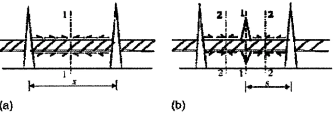
Figure 2.6: Primary and secondary cracking in concrete: (a) section o f highest concrete tension; (b) next section of highest concrete tension... 27
Figure 2.7 Moment-curvature relation o f FRP- reinforced concrete [CAN/CSA-S806, 2012] 30 Figure 2.8 Stress-Strain curves for reinforcement [MacGregor 2009]... 37
Figure 2.9 Stress-Strain curves for reinforcem ent...39
Figure 2.10 The four-point bending loading d iag ram ...42
Figure 3.1 GFRP reinforcing b a rs ... 54
Figure 3.2 Dimensions, reinforcement details, and instrum entation... 57
Figure 3.3 Moment-to-maximum concrete and reinforcement strain relationship...64
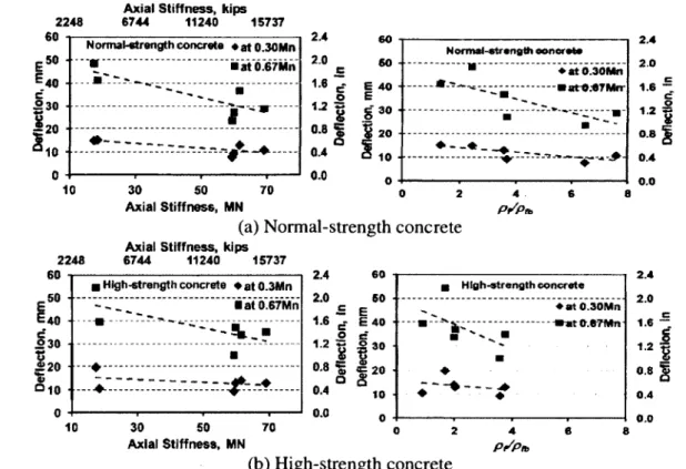
Figure 3.4 Load-to-mid-span deflection relationships: (a) Series I, II, IV; (b) Series II, III, IV 66 Figure 3.5 Deflection versus the axial-reinforcement stiffness and p/pjb'- (a) Normal-strength concrete; (b) High-strength concrete... 69
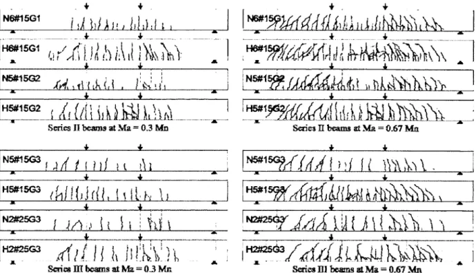
Figure 3.6 Crack patterns of beam specimens o f Series II and III at 0.3M„ and 0.67M „... 71
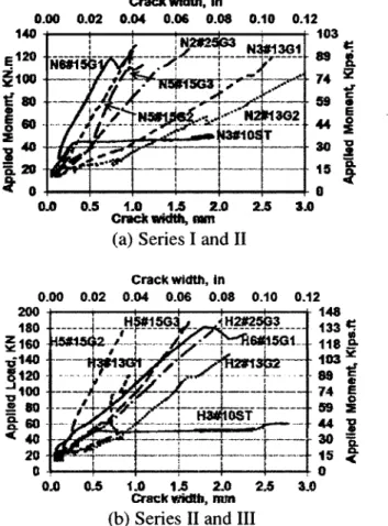
Figure 3.7 Moment-to-maximum crack-width relationships: (a) Series I and II; (b) Series II and I I I ...73
Figure 3.8 Predicted moment-to-crack-width relationships using different kf, v a lu e s... 79
Figure 4.1 Surface configurations of the FRP reinforcing bars... 93
Figure 4.2 Dimensions, reinforcement details, and instrum entation... 95
L ist o f F igures
Figure 4.4 Moment-to-reinforcement strain relationships (a) Normal-strength-concrete beams;
(b) High-strength-concrete beam s...102
Figure 4.5 Moment-to-maximum crack-width relationships: (a) Groups I and II and 3#10C1; (b) Groups III and IV and 3#13C1 ; (c) Groups VI to I X ...105
Figure 4.6 Crack width to strain in reinforcement relationships... 106
Figure 4.7 Crack width versus p/pp,'. (a) Normal-strength concrete beams; (b) High-strength concrete b e a m s... 107
Figure 4.8 Predicted moment-to-crack-width relationships according to ACI 440.1R-06 [2006], ISIS Manual No.3 [2007], and CAN/CSA-S6.1S1 [2010] for normal-strength concrete beam s... 113
Figure 4.9 Predicted moment-to-crack-width relationships according to ACI 440.1R-06 [2006], ISIS Manual No.3 [2007], and CA N/CSA-S6.1S 1 [2010] for high-strength concrete beam s... 114
Figure 5.1 GFRP reinforcing b a rs ...127
Figure 5.2 Dimensions, reinforcement details, and instrum entation...129
Figure 5.3 Test setup during a beam testing...130
Figure 5.4 Typical compression failure of beams reinforced with GFRP bars Type G2 and G3. ... 133
Figure 5.5 Moment-to-maximum concrete and reinforcement strain relationship: (a) and (b) for GFRP-1 (Grade I and II); (c) for GFRP-2 and (d) for GFRP-3 (Grade III)... 135
Figure 5.6 Deflection vs. applied moment for beams reinforced with different GFRP Grades: (a) and (b) for GFRP-1, while (c) for GFRP-2 and (d) for G F R P -3 ...137
Figure 5.7 Deflection versus p/pp, and curvature W \I d ...139
Figure 5.8 Crack patterns of beam specimens o f Series I, III and V at 0.3M n and 0.67M„ 144 Figure 5.9 Crack width vs. applied moment for beams reinforced with different GFRP bars: (a) and (b) for GFRP-1 ; (c) for GFRP-2 and (d) for GFRP-3...145
L ist o f T ables
LIST OF TABLES
Table 2-1 Typical tensile properties o f FRP and steel reinforcing bars [fib., 2 0 0 7 ]... 17
Table 2-2 Grades o f FRP bars corresponding to their minimum modulus of elasticity, (GPa) with typical tested sam p les... 19
Table 2-3 Reduction factor used in the existing guidelines... 21
Table 2-4 shows the minimum thickness required through typical codes and guidelines to control the deflection... 23
Table 2-5 shows the deflection limits adopted from steel reinforced members codes and guidelines [ACI 318, 2008]... 24
Table 3-1 Properties of the Reinforcing B a rs ...55
Table 3-2 Details of the Test Specim ens... 55
Table 3-3 Experimental and Predicted Cracking and Ultimate M om ents... 59
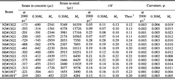
Table 3-4 Strains, Neutral Axis-to-Depth Ratio, and Curvature of Test Specim ens...62
Table 3-5 Experimental-to-Predicted Deflection R atios...68
Table 3-6 Experimental-to-Predicted Crack Width (wexi/w pred) and Predicted kb V alue...69
Table 3-7 Experimental-to-Predicted Crack Width {wex/ w pre(j) Using Different kb V alues... 78
Table 4-1 Properties o f the reinforcing b a rs ...93
Table 4-2 Details of the test specim ens...94
Table 4-3 Strains and crack widths of the test specim ens...,..101
Table 4-4 Experimental-to-predicted crack width (wexp/w pre<j) for normal-strength-concrete beams ... I l l Table 4-5 Experimental-to-predicted crack width (wex/ w pred) for high-strength-concrete beams ... I l l Table 4-6 Predicted bond-dependent coefficient (kh) values at different lim its...116
Table 4-7 Average predicted kb values in comparison with design provisions...117
Table 5-1 Properties o f the GFRP b ars...127
Table 5-2 Details of the test specim ens...128
Table 5-3 Experimental and predicted cracking and ultimate mom ents...131
Table 5-4 Strains, neutral axis-to-depth ratio, and curvature of test specim ens...134
_____________________________________________________________________________________________List o f Tables
Table 5-6 Experimental-to-predicted crack widths (wexp/wpred) ... 146 Table 5-7 Deformability of the tested beams at ec = 1,000 pe and Ef r p= 2,000 p e... 148
N om en clatu re
NOMENCLATURE
A = effective tension area o f concrete surrounding the flexural tension reinforcement and
<y
bearing the same centroid as that reinforcement, divided by the number o f bars (mm );
a = shear span (mm);
A f = area of FRP tension reinforcement (mm2);
b = effective width o f beam (mm);
c = neutral axis depth (mm);
c/d = neutral axis-to- depth ratio;
d = distance from the extreme compression fiber to the centroid o f tension force (mm);
db = bar diameter (mm);
dc = distance from extreme tension fiber to the centre o f the longitudinal bar or wire located closest thereto according to the code or guideline (mm);
Ec = modulus o f elasticity of concrete (MPa);
Ef = modulus o f elasticity of longitudinal FRP reinforcement (MPa);
Es = modulus o f elasticity of longitudinal steel reinforcement (MPa);
f c = compressive strength of the concrete (MPa);
f f = stress in FRP reinforcement under specified loads (MPa);
fjrpu = characteristic tensile strength (average - 3 standard deviation (SD))
N om en clatu re
f c = guaranteed tensile strength (average - 3 standard deviation (SD));
f r = modulus of rupture (MPa);
f r = modulus of rupture (MPa);
f s = stress in reinforcement at serviceability limit state and shall be calculated on the basis of a cracked section;
/, = tensile strength from cylinder-splitting test (MPa);
f y = yield strength o f steel longitudinal reinforcement (MPa);
hi = distance from neutral axis to center o f tensile reinforcement (mm); /z2 = distance from neutral axis to extreme tension fiber (mm);
I Cr = transformed moment of inertia o f cracked reinforced concrete section (mm4);
le - effective moment of inertia (mm4);
If. = gross moment o f inertia of un-cracked section (mm4);
J = Deformability factor.
kb = bond-dependent coefficient;
L = length o f clear span (mm);
Lg = length o f the un-cracked section (mm);
Ma = applied moment (kN.m);
Mcr = cracking moment (kN.m); Mcr = cracking moment (kN.m);
N om en clatu re
M„ = nominal moment o f the reinforced-concrete section (kN.m);
Ms = Service moment at a corresponding concrete strain of 1,000 microstrains or 2,000 microstrains in the FRP reinforcement as defined by Newhook eta l., [2002] (kN.m);
Mu = Ultimate moment (kN.m);
My = moment corresponding to the yield stress o f the steel bars (kN.m);
P = applied load (kN);
s = spacing between the longitudinal reinforcement bars (mm);
SD = standard deviation;
w = maximum crack width (mm);
y, = distance from centroid axis of cross-section to the extreme fiber in tension (mm);
z = maximum stresses at crack width initiated adopted by CAN/CSA-S806, [2012]
(N/mm);
<5 = mid-span deflection (mm);
ecu = ultimate strain of concrete; Pf = longitudinal reinforcement ratio;
Pjb - balanced longitudinal reinforcement ratio.
ip = curvature;
*PS = curvature at a corresponding concrete strain o f 1,000 microstrains or 2,000 microstrains in the FRP reinforcement as defined by Newhook et al., [2002];
N om en clatu re
CHAPTER 1
INTRODUCTION
1.1 Background and Problem Definition
Considerable damage o f reinforced concrete structures occurs due to the corrosion of steel reinforcement and related deteriorations. This problem is a major challenge for the construction industry, especially, when the reinforced concrete structures are subjected to harsh environmental conditions. These conditions normally accelerate the need o f costly repairs and may lead to catastrophic failures. Due to its non-corrosive nature, the fiber- reinforced polymer (FRP) reinforcement is being used as an alternative to steel bars to overcome the common corrosion problems and deteriorations. The recent advancement in the FRP technology led to introducing FRP bars with enhanced mechanical properties and surface configurations, which is expected to increase the use of FRP. In addition, the recently published standards for the FRP specifications [CAN/CSA-S807, 2010] provided a step forward for increasing the use of FRP materials and for introducing them to new applications.
The FRP bars have different mechanical and bond properties compared with those of steel bars. The FRP bars are characterized by very high tensile strength, relatively low modulus of elasticity, and linear stress-strain behaviour until failure. The low er modulus o f FRP bars yields large strains being developed in the bars at low load levels creating large crack widths and deflections. As a result, the design o f concrete members reinforced with FRP materials is governed by the serviceability limit state (SLS) rather than the ultimate limit state (ULS) [Mathys and Taerwe, 2000; Nanni, 2003]. Due to lack o f standards, a wide variety of FRP products with different properties and surface configurations are commercially available.
C h a p ter 1: Introduction
The FRP bars could vary significantly because their properties are relying on type of fiber, type o f resin, and manufacturing process in addition to the surface and/or coating characteristics [Ceroni et al., 2006; Baena et al., 2009]. Consequently, the design models and guidelines are required to cope with all the available FRP products. Furthermore, most o f the FRP design codes and guidelines are based on adopting the design equations for steel reinforced members with some modifications to account for the different mechanical and/or bond properties. Thus, the design equation may yield good results with one type of FRP bars and discrepancy with any other type.
Serviceability (deflection and crack width) is also one of the most important issues in designing the FRP reinforced concrete members due to the lower modulus o f elasticity of FRP than that of steel. For deflection, coefficients were proposed to modify Branson’s equation used in steel design codes [ACI 318, 2008], while other suggestions were introduced to use the modified equivalent moment of inertia derived from the integration of curvatures along the beam. These different approaches were adopted in various FRP design codes and guideline for predicting the deflection o f FRP reinforced concrete beams [ACI 440.1R-06, 2006; ISIS Manual No.3, 2007; CAN/CSA-S806, 2012], On the other hand, cracking behaviour of FRP reinforced concrete elements, design equations and prediction models are generally based on similar formula to that of steel reinforced concrete such as Gerlgy-lutz and Frosch formula with coefficient that depends on the different characteristics o f the bars and their interaction with concrete, however, the design formula for crack width is still under discussion even for steel reinforced concrete [Beeby, 2004; Beeby et a i , 2005; fib., 2010]. In addition, the crack width calculations include the effect of bond between the FRP bars and the surrounding concrete; which is normally included in the FRP design codes and guidelines through what-so- called bond-dependent coefficient (kb), while the interpretation o f this coefficient remains
C h a p ter 1: Introduction
ambiguous [McCallum et Newhook, 2012], The FRP design codes and guidelines provide unique values for the bond-depended coefficient (kb) depending on the surface characteristics of the bar only and neglecting FRP bar type, diameter, and surrounding concrete type and strength.
Based on the results from the literature and considering the different available FRP products, there is a need for further investigation concerning the flexural response and serviceability performance o f FRP reinforced concrete members using normal- and high- strength concretes.
1.2 Research Objectives
This study aims at investigating the flexural behaviour and serviceability behaviour of FRP reinforced concrete beams reinforced with different types o f FRP bars and fabricated using normal- and high-strength concretes. The study focused on three types of glass FRP bars and one type of CFRP bars as they are being used extensively in Canada. Few studies were conducted on high-strength concrete beams; however, many extensive studies were conducted by normal-strength concrete. Thus, this study included both normal- and high-strength concretes. The specific objectives o f this study are:
- To investigate the flexural of concrete beams reinforced with different types and ratios of glass and carbon FRP bars using normal- and high-strength concretes;
- To investigate the serviceability (cracking and deflections) performance o f normal- and high-strength concrete beams reinforced with FRP bars;
C h a p ter 1: Introduction
- To evaluate the current design approaches of the FRP reinforced concrete beams at service and ultimate load levels (SLS and ULS) and to evaluate the applicability of the design provisions on both concrete types (normal and high-strength);
- To evaluate the bond dependent coefficient ( k b ) recommended by current design codes
and guidelines and check the dependency o f kb values on FRP bar type (glass and carbon), FRP diameter, and concrete strength.
1.3 Methodology
To achieve the aforementioned objectives, an extensive experimental program was conducted. The program included full-scale simply supported concrete beams reinforced with different types and ratio of FRP bars. The beams measured 4250-mm long x 200-mm wide x 400-mm deep. The test parameters were the type o f FRP reinforcing bars, reinforcement ratio, bar diameter. The beams specimens were fabricated with normal- and high concrete strengths (NSC and HSC). The experimental program aspects (materials, specimens, testing, and analysis are summarized in this section:
a- Materials:
Reinforcement:
(i) GFRP-1: Sand Coated glass FRP bars of diameters 13, 15, 20, 22, and 25 mm having fiber content ratio (by weight) o f 80.8%, 81.4%, 82.7%, 82.5% and 82.3%, with two different grades of modulus o f elasticity (46.4 to 53.2 GPa);
C h a p te r 1: Introduction
(ii) GFRP-2: Sand Coated glass FRP bars of diameters 13, 15, 20, and 25 mm having fiber content ratio (by weight) of 81.7%, 81.4%, 81.6%, and 82.4%, with two different grades of modulus o f elasticity (52.5 to 69.3 GPa);
(iii) GFRP-3: Helically-grooved glass FRP bars of 15, and 25 mm diameter having fiber content ratio of 86.7% and 88.6%, with standard modulus of elasticity close to 60 GPa;
(iv) CFRP-1: Sand Coated carbon FRP bars of diameter 10, and 13 mm having fibre content ratio of 78.8% and 75.9%, with standard modulus elasticity around 140 GPa;
(v) Conventional 10M and 15M steel o f diameter 15.9 mm as well as smooth steel bars o f 10 mm diameter for steel stirrups, with standard modulus of elasticity of 200 GPa.
Concrete:
Ready-mixed normal- and high-strength concretes (NSC and HSC) with 28-day target compressive strengths of 30 and 65 MPa, respectively, were used. The composition of the concrete mix of both concrete types was as follows:
(i) Normal Concrete Strength: A cubic meter of the NSC contained 350 kg of cement, 813 kg of sand, and 1032 kg o f aggregate with a water/cement ratio (w/c) of 0.44 and air entrained ratio of 5-6%. The maximum aggregate size was 20 mm.
(ii) High Concrete Strength: A cubic meter of HSC contained 490 kg of cement, 813 kg of sand, and 1032 kg of aggregate with a water/cement ratio (w/c) o f 0.32 and 0% o f air entrained. The maximum aggregate size was 14 mm.
C h a p ter I: Introduction
b- Instrumentation and testing:
(i) 500 KN hydraulic actuator used for applying the load with stroke-controlled rate of 0.6 mm/min. The Beams were tested in four-point bending over a clear span of 3750-mm.
(ii) Electrical strain gauges of 10 and 60 mm length and 120 ohm resistance
manufactured by Kyowa limited for measuring strains along the reinforcing bars. (iii) Six high precision linear variable displacement transducers (LVDTs) for
measuring deflection along the beam at different load levels as well as the crack width evolution during the test after determining their initial widths using a hand held microscope of 50X magnifying power.
(iv) A data acquisition system comprising 60 channels controlling the loading, strain gauges, and LVDTs for cracking and deflection.
c- Analysis:
(i) Analyzing the flexural behaviour and serviceability performance of the beams and discussing the test results in the light o f the codes and guidelines recommendations and requirements. Strains, crack widths, and deflections were compared and conclusions were drawn. The bond dependent coefficient kb for cark width prediction was also assessed and evaluated. The codes’ equations were compared against the experimental results and conclusions were drawn.
C h a p ter 1: Introduction
1.4 Structure of the Thesis
The thesis comprises seven chapters; three of them (chapters 3 to 5) presents papers accepted/submitted to Journals. The following is a brief description of each chapter’s content:
Chapter 1: This chapter defines the problem and presents the main objectives of this study.
The methodology followed to achieve the objectives of this research program is also highlighted and the structure of the thesis is presented.
Chapter 2: This chapter provides a literature review on the serviceability of FRP reinforced
concrete members. This chapter also presents the main factors influencing the deflection and crack width o f FRP reinforced concrete beams. The currently available equations for flexural capacity, deflection and cracking in the design codes and guidelines in North America are also summarized.
Chapter 3: This chapter includes a paper submitted to the ACI Structural Journal. The paper
investigated the flexural behaviour and serviceability performance of GFRP reinforced concrete beams in terms of deflection, crack width, strains in concrete and reinforcement, flexural capacity, and mode of failure. The results were verified against the current deflection and crack-width prediction equations in the North American FRP design guidelines and Canadian codes.
Chapter 4: This chapter includes a paper submitted to the ASCE Journal of Construction
Composites. The paper aimed at investigating the current design recommendations for the bond-depended coefficient (kb) values and verifying the dependency of the kb values on FRP bar type, diameter, and concrete type and strength. The findings did not support the unique kb
C h a p te r 1: Introduction
value for FRP bars of different types with similar surface configurations. Moreover, kb was found to be dependent on bar diameter.
Chapter 5: This chapter includes a paper submitted to the Canadian Journal of Civil
Engineering. This paper evaluates the flexural behaviour and serviceability performance of concrete beams reinforced with GFRP bars o f different grades and surface configurations. The results were presented in terms of serviceability and flexural performance and verified against the current serviceability prediction equations o f North American FRP design guidelines and Canadian codes. The Deformability of FRP reinforced concrete beams are also evaluated and discussed in the lights of the codes’ requirements.
Chapter 6: This chapter includes the overall conclusions of this study based on the findings. In
CHAPTER 2
LITERATURE REVIEW
2.1 Background
Concrete material is strong in compression and weak in tension. Thus, the behaviour presents a brittle behaviour in tension. Reinforcing concrete with steel has been traditional solution to the brittle act of concrete under tension. Because of its mechanical properties, steel provides well flexure behaviour when used as reinforcement in concrete members.
Although its adequate bond transfer as reinforcement, the steel corrodes rapidly under aggressive conditions such as severe weather where deicing salts are used. Thus, with the development of composite materials, Fiber reinforced polymer (FRP) emerged an alternative substitute were used instead o f steel, especially when durability under aggressive conditions is required.
These materials have different mechanical properties from steel, in addition, to their surface textures which affect the bond transfer mechanism between the bar and the surrounding concrete. This chapter includes a review of the basic aspects that affect the flexural behaviour o f FRP reinforced concrete members.
The chapter is describing the main mechanical properties o f concrete and FRP bars as internal reinforcement of reinforced concrete in according to CAN/CSA-S807 [2010] classification. In addition, the chapter gives a brief summary about the FRP manufacturer and its new development. Also, a brief summary on service limit states adopted by different codes and guidelines is presented.
C h apter 2: L iteratu re R eview
Then after, an overview of the flexural capacity o f reinforced concrete beams in terms of current equations available in codes and guidelines were validated. Moreover, the design prediction equations for deflection and crack width recently adopted by codes and guidelines were presented and described with their limitations.
2.2 Material properties
2.2.1 Concrete:
Several test books provides many information and models on concrete properties [Neville, 1970] but most were limited to quasi-static and one-dimensional states of stress- strain. More review o f this information is given by Aoyama et Noguchi, [1979]. Furthermore, extensive reviews have also been given by Newman [1966], Brooks et Newman [1968] and Shah [1980] on high concrete strength.
Concrete forms a large number of micro cracks, especially at interfaces between coarser aggregates and mortar even before any load has been applied [Chen et Saleeb, 1982]. Thus, the propagation of these micro cracks during loading contributes to nonlinear behaviour of concrete at a low stress level and causes the volume expansion near failure. These micro cracks may be caused by segregation, shrinkage or thermal expansion in mortar developed during loading through the differences in stiffness between aggregates and mortar. The mechanical behaviour of concrete is strong in com pression and weak in tension due to the aggregate mortar interface that has lower tensile strength.
The constitutive relationship of concrete under uniaxial is commonly derived from experimental tests on cylinders with a height to diameter ratio of 2. From this test, a typical
C h apter 2: L iteratu re R eview
stress-strain relationship can be deduced for concrete when subjected to uni-axial compression as shown in Figure 2.1.
The stress-strain curve has nearly linear-elastic behaviour up to about 30% o f its maximum compressive strength f c. For stresses above this point, the curve shows a gradual increase in curvature up to about 0.75 f c to 0.90 f c according to the concrete strength (normal - or- high concrete strength), then after it bends sharply and approaches the peak point at f c. Beyond this peak, the stress-strain curve is descending till crushing failure occurs at the ultimate strain e„. This stress-strain curve (Figure 2.2) has been studied extensively and several models were proposed to describe such curve depending on several factors [Hognestad, 1951 ; Hognestad et al., 1955; Todeschini et al., 1964],
Tangent modulus -,
i/i
ÜÏ
a> Secant m odulus at stre ss B
Initial tangent modulus
O Strain
C h apter 2: L iteratu re R eview Linear 0.C038 O 10 Vi £ S t r a i n , < Strain. « (r>) T o d o sch ln i. (From |3 -4 i J
(a) Modified Hognestad (b) Todeschini.
Figure 2.2 Analytical approximation to the concrete compressive stress-strain curve [MacGregor 1997]
Most codes and guidelines [ACI 318, 2008; CAN/CSA-A23.3, 1994; ACI 318, 1999] adopted the model proposed by Collins and Mitchell (1993). The expression relates the stress fc and strain at that stress, ec. Many other models were provided by Model Code 90 [CEB-FIP. 1990], Euro Code 2[CEN. 2004], [fib. 2007], All of them were limited to concrete with characteristic strengths o f up to 65 MPa, except that adopted by Euro code 2 [CEN. 2004] which is limited to concrete strength was up to 90 MPa.
On the other hand, the concrete behaves linearly under tensile stress until it reaches its ultimate tensile strength [MacGregor 1997]. For values of strain larger than that corresponding to the ultimate tensile strength, the stress decreases with an increase of the measured strain.
Since cracking is a discrete phenomenon and cannot locate cracking position, the strain along tensile reinforced element is not constant [Barris 2010]. In cracked concrete element, the
C h apter 2: L iteratu re R eview
concrete zone between two consecutive cracks contributes to load-carrying capacity through the bond stress transfer between the concrete and reinforcement. This phenomenon produces an increment of the stiffness of the element and is extensively known as tension stiffening that will be discussed later in this chapter.
2.2.2 Fibre reinforced polymer (FRP):
Composite materials can be defined on those materials resulting from the contribution of two or more components or constituents. FRPs have been used for decades in the aeronautical, aerospace, automotive and other fields [ISIS M anual No.3, 2007], The first applications o f glass fiber FRP in structural engineering application were not successful due to its poor performance within thermosetting resins cured at high moulding pressure [Parkyn, 1970]. Since their early application, many FRP materials are still developed including different types of fibers and their improvements. Glass, carbon and aramid are m ajor fiber type used manufacturing o f reinforcing bars and could be used in reinforcing structural element although the aramid are still in debate [W allenberger et a i , 2001; Walsh, 2001; Chang, 2001], These fibres were formed from roving, tow, mat, woven fabrics.
Thus, bars made of FRP are considered as innovative material in structural engineering. Their physical and mechanical properties are widely ranged. FRPs are fabricated by choosing the type and quantity o f fiber sand matrix resulting in different characteristics of products depending on the manufacturing process and ratio between fiber and matrix. In addition, FRP bars can have different surface configuration with varying performances in their bond behaviour with concrete, which in turn affect many behavioural aspects such as crack width and deflection.
C h apter 2: L iteratu re R eview
2.2.3 FRP constituents
FRP products are composite materials consisting of continuous fibres impregnated with polymeric resins. As clear, continuous fibres with high strength and high stiffness are embedded and boned together by low modulus polymeric matrix. The reinforcing fibres represents the backbone of material in which determines strength and stiffness in the directions o f fibres, thus, the matrix act as physical and environmental protection [ISIS Manual No.3, 2007].
Carbon fibres are similar to steel in stiffness, durable and expensive in cost. From field application [El-Gamal et al., 2005], the carbon has proven quite resistant to most environmental conditions and can with stand high sustained and fatigue loading conditions. In contrast, glass fibre has lower strength and significantly lower stiffness. One o f recent concerns is to check the durability of glass fibres. Unprotected glass fibre degrades against most environments, especially hot/wet or highly alkaline environm ents [Barris et al., 2009], In addition, it is subjected to creep rupture phenomenon which results in the eventual failure of the materials under sustained loads of fraction from the instantaneous ultimate load. The polymeric matrix (i.e. resin) act as coat for fiber to avoid damage and ensure the alignment of fibre resulting is distributing the load uniformly among many o f the individual fibres in composite.
Two types of resins were used in FRP composites: thermosetting and thermoplastic resins. In construction and structural application, the most utilized resins are the thermosetting, such as epoxy and vinyl ester. The resins are flowable material with low viscosity that should be cured to a final solid form. M ost o f these resins are sensitive to heat and ultra-violet
C h a p ter 2: L itera tu re R eview
exposure. As mentioned earlier, one of the factors that affect mechanical properties o f FRP materials is manufacturing processes. Three common processes are available, such as Pultrusion, braiding, and filament winding [ISIS Manual No.3, 2007], However, Pultrusion is the common technique for manufacturing continuous lengths o f FRP bars o f constant or nearly constant profile. This technique is schematically represented in Figure 2.3 and Figure 2.4 [fib., 2007]. Continuous fibres of reinforcing material are drawn from curls through a resin tank where they are saturated with resin and then through a number o f wiper rings into the mouth of heated die. Thereafter, the surface of the bars is usually braided or sand-coated.
Figure 2.3 Schematic o f a Pultrusion process [fib., 2007]
S u rfa ce ' v e il S e r ie s o f p r e fo r m e r s Fiber r o v in g s , a n d m a ts (s h o w n )
p u lled fro m c r e e ls R esin tan k
C h apter 2: L iteratu re R eview
Figure 2.4 Pultrusion process: fibers/fabrics passing through guidelines and into the resin bath (left and middle part); resin tank at the bottom o f the resin bath (middle portion); addition of surface veils (right part) [fib., 2007].
2.2.4 Mechanical properties of FRP bars
The mechanical properties of the FRP products are specified by fibre quality, orientation, shape, and volumetric ratio, adhesion to the matrix and on the manufacturing process. For example, to provide functioning reinforcing bars the fibre volume fractions should be more than 55%. ACI 440.6M-08 [2008] stated that fibre content should be measured according to ASTM Standards [ASTM D7205, 2011] in which represents the procedure of measuring fibre content in FRP bars or FRP girds. Both them conquered fibre content should at least not be less than 55%. FRP materials, in general, are anisotropic and brittle in nature. Therefore, they are characterised by high tensile strength with no yielding and only in one direction of reinforcing bars.
FRPs bar have linear stress-strain behaviour under tension up to failure, however, they
have lower modulus of elasticity and no ductility like the steel bars.
Figure 2.5 shows stress-strain curves for different types o f FRP bars in the lieu of that o f steel bars. Table 2-1 provides some typical ranges of mechanical properties for each FRP type. This anisotropic behaviour of FRP bars affects the shear strength and dowel action as well as their bond performance [Nanni, 2003]. The use of FRP bars as reinforcing bars offers several advantages in comparison to steel reinforcement.
C h apter 2: L itera tu re R eview C F R P V F R P G F R P R e in fo rc in g steel I n l i ’ (I ’ S VI St r a i n e ( xI O )
Figure 2.5 Stress-Strain curves o f FRP and Steel materials [Pilakoutas et al., 2002]
FRP bars are corrosion resistant, electromagnetic permeability, high cuttability and lighter in weight.
Table 2-1 Typical tensile properties of FRP and steel reinforcing bars [fib., 2007]
Property Material Steel GFRP CFRP AFRP Longitudinal modulus (GPa) 200 35 to 60 100 to 580 40 to 125 Longitudinal
tensile strength 483 to 690 450 to 1600 600 to 3500 1000'to 2500
(MPa) Ultimate tensile
strain (%)
6.0 to 12.0 1.2 to 3.7 0.5 to 1.7 1.9 to 4.4
All these advantages have led the FRP to emerge as an alternative substitute of steel reinforcing in several projects such as marine reinforced concrete structures, M RI rooms in hospitals and mobile telecommunications industry, finally as a temporary diaphragm walls
C hapter 2: L itera tu re R eview
which can be partially destroyed by tunnel boring machines. In addition, they facilitate transportation and speeds construction [ACI 440.1R-06, 2006; fib., 2007; Pilakoutas et al., 2007].
The unique mechanical properties o f FRP represented in lower elastic modulus have significant influence on the structural behaviour o f FRP reinforced concrete element. This yielded to large strains being mobilized in bars at low load levels which in turns lead to larger crack width and deflections. As a result, serviceability requirements often govern the design of FRP reinforced concrete members [Mathys and Taerwe 2000; Nanni, 2003]. Finally, the wide range of commercially available products can differ substantially in terms of mechanical properties and surface characteristics imposes difficulty to develop or im plement simple design rules that can model adequately the mechanical performance of composite bars in concrete. Despite several design guidelines, codes and recommendations have been recently been published for FRP reinforced concrete members [ACI 440.1R-06, 2006; ISIS Manual No.3, 2007; CAN/CSA-S6.1S 1, 2010; JSCE., 1997; IStructE., 1999], the lack of well standards for design and manufacturing is still perceived as a barrier to the extensive use of FRPs in construction.
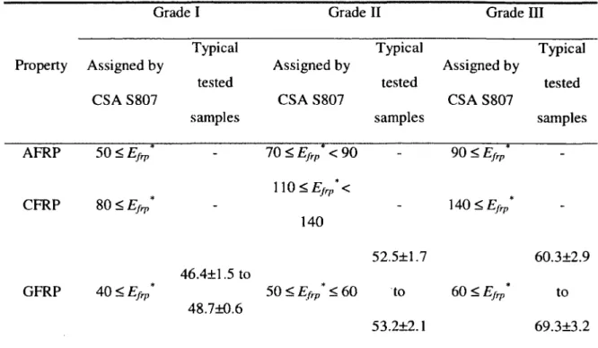
However, many attempts were proposed to classify the FRP bars product into categories such as surface textures, so that each category has their own rules and models. Recently, the CAN/CSA-S807 [2010] classified the FRP bars by considering their elastic modulus. This classification was refereed by Grade I, II, and III. Grade I being the lowest value of elastic modulus and Grade III being the highest value o f elastic modulus. Table 2-2 shows the ranges for each grade, in addition, typical ranges of tested samples included in this research program. Yet, the table did not specify certain rules and laws for each grade.
C hapter 2: L iteratu re R eview
Table 2-2 Grades o f FRP bars corresponding to their minimum modulus of elasticity, (GPa) with typical tested samples
Grade I Grade II Grade III
Property Assigned by CSA S807 Typical tested samples Assigned by CSA S807 Typical tested samples Assigned by CSA S807 Typical tested samples AFRP 50 < E fr; - 70 < E fr p* < 90 - 90 < E frp* -CFRP 80 < E frp -1 -10 < E f rp* < 140 - 140 < E frp* -GFRP 40 < E frp* 46.4+1.5 to 48.7+0.6 50 < E frp * < 60 52.5±1.7 to 53.2±2.1 60 < E frp * 60.3+2.9 to 69.3+3.2 Efrp is the actual elastic m odulus o f FRP bars resulted from testing.
2.3 Maintaining service state
Serviceability limit states (SLS) are limits for reinforced concrete members to ensure their structural integrity under service conditions. As mentioned in the previous section, FRP reinforced concrete members are governed by service limit state rather than ultimate limit state due to their lower elastic modulus and different bond behaviour.
The service limit state is defined generally through many aspects as concurred by researchers, codes and guidelines [ACI 440.1R-06, 2006; ISIS Manual No.3, 2007; CAN/CSA-S806, 2012; JSCE., 1997; IStructE., 1999; CNR-DT 203., 2006], These aspects are limiting the strains in FRP by fraction from their ultimate strains each according to FRP type,
C h apter 2: L iteratu re R eview
30 % of ultimate load, deflection and crack width limits. Also, the situation can be extended to other materials such as concrete.
Stresses in concrete usually limited the developed compressive stress to prevent the longitudinal cracks and micro-cracks from occurrence. No codes or guidelines, prescribed explicitly a specific limits on concrete compression stresses, however, from the design o f flexural capacity. It can be understood that the linear range in which equal to a value o f 0 .4 5 /’, is the appropriate limit for concrete stresses under service condition. On other hand, stresses in FRP reinforcing bars are limited explicitly in two terms reduction for environmental deterioration and limits under sustained loads.
Table 2-3 shows the limits assigned by different existing codes and guidelines.it is clear that both factors, environmental conditions and sustained loads, leads to serve reductions from the ultimate strength o f bar which means slight portion of the FRP strength were used (values are between 0.2 to 0.55 times the ultimate strength).
Other limits were specified such as 30 % o f the ultimate load. This limit was deduced from that o f steel. The steel reinforced concrete members are governed by strength or ultimate limit state. Thus, giving Ma = <p/(aioad) Mn = 0.67M„ when the strength reduction factor tp = 0.9 and the load factor [a/„a</ = 1.33 fo r dead-to-live load ratio o f 2:1] which correspond to roughly 30% of nominal moment capacity M n for FRP reinforced concrete sections to ensure that serviceability requirements (crack width and deflection) are satisfied.
C h apter 2: L iteratu re R eview
Table 2-3 Reduction factor used in the existing guidelines
Factor FRP Type ACI 440.1R-06 CE CAN/CSA S806-12 (pFRP JSCE 1997 l/yfm IStructE i/y m CNR-DT-203 4a Reduction for GFRP 0.70-0.80 0.50 0.77 0.70-0.80 “material environmental AFRP 0.80-0.90 0.60 0.87 0.80-0.90 factor” deterioration CFRP 0.90-1.0 0.75 0.87 0.90-1.0 0.8 x Stress m
GFRP 0.20 0.25 “creep limits not 0.30
Stress limit for AFRP 0.30 0.35 failure specified 0.50
sustained load strength”
CFRP 0.55 0.65 0.90
< 0.7
However, [Bischoff 2005] suggested to lower service load levels to about 0.30M n or less to ensure strains in FRP reinforcement are within the acceptable lim it especially where service load related to strength requirement (Ma = 0.49M n when tp = 0.65 fo r p > 1.4pb). Other limits such as crack width and deflection limits were used to control serviceability of FRP reinforced member. These limits were discussed in the following sections.
Control o f cracking:
In general, cracking usually controlled to prevent leakage of fluid in structures that support water or any other liquids and to prevent corrosion o f reinforcement which in turn weakened the durability of structure. In steel reinforced concrete members, the primary reason for crack
C hapter 2: L itera tu re R eview
width limitations is the corrosion of reinforcement. As FRP reinforcing bars are corrosion resistant, thus, the crack width limit was relaxed by all codes and guidelines. For the steel reinforced concrete member, most codes and guidelines limited the maximum crack width to about 0.3 mm, however, others relaxed the limit to 0.4 mm in case o f no aggressive exposure by means no risk o f corrosion or attack. In the ACI 318 [2008], the crack width limit was replaced by bar spacing closet to tension force of the beam. CAN/CSA-A23.3 [2004] distinguishes between exterior and interior exposures, by values of 0.3 and 0.4 mm as limit for maximum crack width, respectively.
The limitation for FRP reinforced member was relaxed to 0.5 mm for exterior exposure and 0.7 mm for interior exposure [ACI 440.1R-06, 2006; ISIS Manual No.3, 2007]. Other codes and guidelines used the limit o f 0.5 mm only in both cases [JSCE, 1997]. Furthermore, ISIS Manual No.3 [2007] suggested controlling the crack width by limiting the maximum strain in FRP to 2000 microstrains. This was obtained through comparing with steel crack width limit. In steel reinforced concrete member, the stress limit in steel reinforcement at service is at 60% of f y. When f y = 400 MPa, the allowable strain in steel bars in service es is equal to 1200 microstrains. At the same time, the crack width was limited by 0.4 and 0.3 mm for interior and exterior exposure in comparison to 0.7 and 0.5 mm for FRP reinforced elements.
Thus, the allowed crack width in FRP reinforced members is about 1.5 to 1.7 times that of steel reinforced. For that reason, it was assumed the strain limit should be around 2000 microstrains for FRP reinforced concrete member which represents 5/3 ratio from 1200 microstrains for steel reinforced concrete member. This ratio was deduced from crack width
C h apter 2: L iteratu re R eview
limit difference. Likewise, CAN/CSA-S806 [2012] defines the quantity z not to exceed 45 kN/mm for interior exposure and 38 kN/m for exterior exposure.
Control o f deflection:
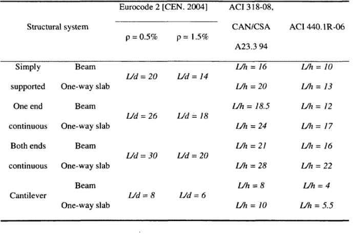
Codes and guidelines proposed different deflection limitations for relative parts of elements to the supports. All limitations were provided so that the deformation of a member or structure shall not affects its proper functioning or appearance. Thus to control deflection the codes and guidelines suggested minimum thickness calculated empirically (Table 2-4).
Some of these codes and guidelines set an equation to calculate the thickness required [ACI 440.1R-06, 2006; CEB-FIP., 1990],
Table 2-4 shows the minimum thickness required through typical codes and guidelines to control the deflection
Structural system Eurocode 2 [CEN. 2004] p = 0.5% p = 1.5% ACI 318-08, CAN/CSA A23.3 94 ACI 440.1R-06 Simply Beam U h = 16 U h = 10 L/d = 20 L/d = 14
supported One-way slab L/h = 20 U h = 13
One end Beam IJh = 18.5 U h = 12
U d = 26 L/d = 18
continuous One-way slab U h = 24 L/h = 17
Both ends Beam U h = 21 U h = 16
U d = 30 L/d = 20
continuous One-way slab U h = 28 L/h = 22
Beam U h = 8 L/h = 4
Cantilever L/d = 8 L/d = 6
C hapter 2: L iteratu re R eview
Table 2-5 shows the deflection limits adopted from steel reinforced members codes and guidelines [ACI 318, 2008]
Type of member Deflection to be considered
Deflection limitation Flat roofs not supporting or attached to non-
structural elements likely to be damaged by Immediate deflection due to live load L 1/180'‘
large deflections.
Floors not supporting or attached to non-
structural elements likely to be damaged by Immediate deflection due to live load L 1/360*
large deflections.
Roof or floor construction supporting or attached to non-structural elements likely to
That part of the total deflection occurring
after attachment of non-structural elements 1/480*
be damaged by large deflections.
Roof or floor construction supporting or attached to non-structural elements not
(sum of long-term deflection due to all
sustained loads and the immediate
deflection due to any additional live load)+ 1/240*
likely to be damaged by large deflections.
Limit not intended to safeguard against ponding. Ponding should be checked by suitable calculations o f d eflection, including added deflections due to ponded water, and considering long-term effects o f all sustained loads, camber, construction tolerances, and reliability o f provisions for drainage.
f Long-term deflection shall be determined in accordance w ith 9.5.2.5 or 9.5 .4 .3 , but may be reduced by am ount o f deflection calculated to occur before attachment o f non-structural elem ents. This amount shall be determ ined on basis o f accepted engineering data relating to tim e-deflection characteristics o f mem bers sim ilar to those b ein g considered. * Limit m ay be exceeded if adequate m easures are taken to prevent damage to supported or attached elem ents.
8 Lim it shall not be greater than tolerance provided for non-structural elem ents. Lim it may be exceed ed i f cam ber is provided so that total deflection minus cam ber does not exceed lim it
![Figure 2.2 Analytical approximation to the concrete compressive stress-strain curve [MacGregor 1997]](https://thumb-eu.123doks.com/thumbv2/123doknet/5406663.126104/31.920.154.793.96.390/figure-analytical-approximation-concrete-compressive-stress-strain-macgregor.webp)
![Table 2-1 Typical tensile properties of FRP and steel reinforcing bars [fib., 2007]](https://thumb-eu.123doks.com/thumbv2/123doknet/5406663.126104/36.919.148.808.498.857/table-typical-tensile-properties-frp-steel-reinforcing-bars.webp)