ISMRE'2018
CFD Modeling of Thermophysical Properties
Influence on The Heat Transfer in Metal Foam Heat
Sinks
Boulahrouz SalimDepartment of Mechanical Engineering Abbes Laghrour University Khenchela, 40000, Algeria. boulahrouz_salim@yahoo.fr
Chahaoui Oualid
Department of Mechanical Engineering Abbes Laghrour University Khenchela, 40000, Algeria.
oualid.chahaoui@yahoo.fr
Abdelmadjid Chehhat Department of Mechanical Engineering
Abbes Laghrour University Khenchela, 40000, Algeria.
achehhat@gmail.com Ghelani Laala
Department of Mechanical Engineering Abbes Laghrour University Khenchela, 40000, Algeria.
ghilanilaala@yahoo.fr
Abdelaziz Aboudi
Department of Mechanical Engineering Abbes Laghrour University Khenchela, 40000, Algeria. abboudiabdalaziz@yahoo.fr
Chermime Brahim
Department of Mechanical Engineering Abbes Laghrour University Khenchela, 40000, Algeria.
cherbrah@yahoo.fr Abstract— This study presents a CFD simulation by
COMSOL multiphysics software of a metal foam heat sink used for cooling electronic power component. The simulation is a transient 3D of air laminar flow through a channel equipped with a plate-electronic component system cooled by a metal foam heat sink. The goal is to determine the thermohydraulic behavior of the system. The foam heat sink is considered as a porous medium, the Darcy-Forchheimer-Brinkman model is used. We discussed the effects of air velocity, heat flux dissipated by the electronic device and the type of metal foam on the system phenomenology.
Keywords—metallic foam, heat sink, comsol, simulation.
I. INTRODUCTION
The use of open-cell metal foams have been widely increasing given by its diverse properties in various areas including aerospace, electronics and automotive. These cellular materials are considered one of the most promising enhanced surfaces by virtue of their intrinsic multifunctional features: high heat transfer area to volume ratio, good stiffness and strength, enhanced flow mixing capability. Therefore, metal foams have considerable possible applications in heat exchangers [1], fuel cells [2], metal foam reactors [3], solar air receivers [4], compact heat sinks for power electronics [5, 6]. Metallic foams are used for other important industrial applications such as: cladding on buildings, strain isolation, geothermal opera-tions, petroleum reservoirs, cryogenics, catalytic beds, com-pact heat exchangers for airborne equipment, air-cooled condensers for air conditioning and refrigeration systems [7, 8]. Several investigations on the determination of the heat transfer and fluid flow characteristics of metallic foam have been conducted over the last twenty years. Bhattacharya et al. [9] provided analytical and experimental results for the effective thermal conductivity for high porosity metal foams. They used a range of high porosity materials of 90 < ε < 98% and 5, 10, 20 and 40 PPI pore densities. The analytical model represented the foam by a two-dimensional array of hexagonal cells. The porosity and the pore density were used to describe the porous media. Experimental data with aluminum foams using air and water as the fluid media were used to validate the analytical solutions. Their experimental work also made use of the Forchheimer equation to describe the flow parameters. Phanikumar and Mahajan [10] numerically and experimentally studied the buoyancy
induced flow in a high porosity aluminum foam heated from below and indicated the two-equation energy model is a better model when fluid/porous interfaces are involved. Haji-Sheikh and Vafai [11] provided analysis of heat transfer in porous media imbedded inside ducts of different shapes, by solving the governing equations assuming local thermal equilibrium, and applying a constant-wall-temperature boundary condition. Alvarez–Hernandez [12] and Dukhan [13] presented experimental results for the pressure drop of airflow through samples of open cell aluminum foam for various porosities and pore densities. Minkowycz and Haji-Sheikh [14] solved the local-thermal-equilibrium equations for the case of parallel plates and circular porous passages including the effect of axial conduction. Kopanidis et al. [15] presented a 3D numerical simulation methodology for the flow and heat transfer at the pore scale level of high porosity open cell metal foam. The conjugate flow and temperature fields were obtained by solution of the Navier–Stokes and energy equations for two different foam pore densities under various flow and temperature conditions. Chen et al. [16] presented a numerical investigation for enhanced heat transfer from multiple discrete heated sources in a horizontal channel by metal-foam porous layer. Both Darcy–Brinkman Forchheimer flow model and two-equation energy model based on local thermal non-equilibrium were used to characterize the thermo-flow fields inside the porous regions. A stream function–vorticity analysis solution was used to resolve the coupled governing equations for the porous/ fluid composite system. Bai and Chung [17] developed a simplified analytical model and a unit-cell CFD model to predict the heat transfer capability and the pressure drop in metal foams. Dukhan and Ali [18] presented results of a systematic experimental study targeting the effect of foam sample diameter and wall effects on the viscous and form contributions to the pressure drop for air flow through aluminum foam. Ranut et al. [19] presented a 3D approach based on the X-ray computed microtomography (μ-CT) technique. The results were performed on three different cell aluminum foams samples and showed that open-cell aluminum foams are effective means for enhancing heat transfer.
In this paper, we present a CFD simulation of heat transfer and air flow through a channel equipped with an electronic plate - device system cooled by a metal foam heat sink. The COMSOL multiphysics software is used to solve the equations and numerically simulate the studied system
using the finite element method. The effects of the air velocity, the heat flux dissipated by the electronic component and the metallic foam on the system phenomenology.
II. THERMO-FLUID MODEL A. Problem Description
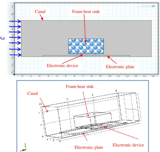
We consider a laminar flow of air through a channel with an electronic component with a metal foam heat sink (Figures 1 and 2). The objective is to determine the thermohydraulic behavior of the system under an imposed heat flux dissipated by the electronic device, and a constant air velocity at the inlet of the channel. we try to discuss the effects of parameters like thermal flux, air velocity and the type of metal foam on the system’s phenomenology.
B. Assumptions
For a simple formulation of the mathematical model we will consider the following hypotheses:
the porous medium (foam heat sink) is isotropic and homogeneous.
The flowing fluid is Newtonian, viscous and incompressible.
The flow is laminar.
The thermal dispersion is negligible.
The viscous dissipation in the energy equation is negligible.
The interactions between the heat and mass transfers known under the name of effects Soret and Dufour respectively are negligible.
The thermophysical properties of the fluid (other than the density) are constant and are evaluated at the reference temperature and concentration. C. Mathematical formulation
Under the above assumptions, the two dimensional steady state macroscopic conservation equations for mass, momentum and energy of solid and fluid phases are as follows; • Continuity equation: 0 y v x u (1)
• Momentum equations: x-momentum equation:
) ( ) ( 2 2 2 2 2 y u x u u V K C K u x p y u v x u u f F f
(2) y-momentum equation: ) ( ) ( 2 2 2 2 2 y v x v v V K C K v y p y v v x v u f F f
(3)• Energy conservation equations:
Energy conservation equation for the fluid phase:
sf sf
s f
f d fe f d fe f f f p T T a h y T k k y x T k k x y T v x T u C ) ( ) ( ) ( (4)Energy conservation equation for the solid phase:
f s
sf sf s se s se h a T T y T k y x T k x ( ) ( ) 0 (5)The dimensionless parameters used in the present study are:
wx i
f wx w f sf x f sf sf fs i w i k T T H q k H h Nu k H h Nu H u H q T T H y H x X 1 , Re , , Y , f (6)Calmidi [21, 22] developed a model for df/dp as a function of
porosity after modification to reflect the difference between the open cell represent and the three-dimensional dodecahedron structure. The fiber diameter, df, is measured by using a
microscope. The pore diameter dp is estimated by counting the
number of pores in a given length of material.
function) (shape 1 , 1 3 1 18 . 1 0.04 1 G e G d d p f (7) The properties of porous matrix of metal foam, K and CF, formomentum equation are taken from Calmidi [22] as follows:
63 . 1 132 . 0 1 00212 . 0 p f F d d C (8)
11 . 1 224 . 0 2 0.000731 p f p d d d K (9) The thermal properties of metal foam, kfe, kse, kd and αsf, forenergy equation are taken from the literature [23 - 26] and are shown as follows:
air for 0.181 B , 1 0.763 fe se f s eff k k k B k k (10) air for t) coefficien dispersion the ( 0.06 where , C KV kd p (11)
(1 )/0.04
2 1 59 . 0 3 e d d a p f sf (12) 5 f d 37 . 0 6 . 0 f d 37 . 0 5 . 0 f d 37 . 0 4 . 0 10 Re 1000 , Pr Re 26 . 0 1000 Re 40 , Pr Re 51 . 0 40 Re 1 , Pr Re 75 . 0 f d f d f d f f sf sf k d h Nu (13) v d V where f f d Re (14)Figure 1: Open cell aluminum metal foam [1].
Figure 2: Schematic diagram of the metal foam cooling system.
Figure 3: Automatically generated mesh of the channel with the electronic component-plate system and metal foam heat sink.
Foam heat sink Canal
Electronic plate Electronic device
Air
Canal
Foam heat sink
Electronic device Electronic plate
Table 1. Properties of the metal foam [20]. Material ppi (pore-per inch) ε (%) dp (m) k (W.m-1.K-1) Al Cu Gr 40 40 40 95 95 95 3.3x10⁻³ 3.3x10⁻³ 3.3x10⁻³ 393 170 1300 D. Boundary conditions
The following boundary conditions are imposed on the model above. All conditions at the limits are physically significant:
- for t = 0, u = v = 0, T = T0, P = P0.
- for t > 0
at x = 0, y=0 and y=H (upstream of the canal) u = u0, v=0, T = T0, P = P0.
at x = L, y=0 and y=H (downstream of the canal), u = u0, v=0, T = T0, P = P0.
at y = H, x=0 and x=L (upper wall of the canal), u = v = 0,
at y = 0, x=0 and x=L (lower wall of the canal), u = v = 0, at y = 0.2 cm, x=6.5 cm et x=8.5 cm (electronic component-foam interface), = (1,25..1,7 MW/m3) imposed thermal flux.
E. Mesh consistency
In order to determine to which number of elements the solution of the partial differential equations (PDEs) govern the adopted model, a study of the consistency of mesh is necessary. The COMSOL mesh uses triangular elements with a refinement of local triangular element. The metal foam model has been solved five different times. The number of elements used to create the mesh (500 elements, 1030 elements, 1630 elements, 3130 elements and 6606 elements) was adopted in order to determine the most effective mesh size (in terms of the change of the resulting temperatures compared to the calculation time). Figures 4.a and b show the temperature profiles inside the metal foam with respect to the dimensionless axes Y and X, respectively. The solution is constant with variation less than 1E-03% to the number of elements (N) = 6606 elements.
III. RESULTS AND DISCUSSION A. Effect of air velocity at the entrance of the canal
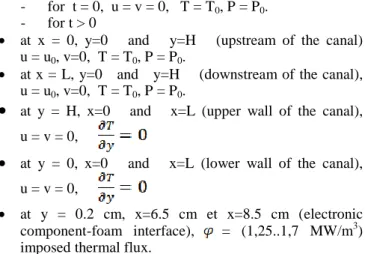
The transient 3D simulation of the air flow through the channel comprising the electronic component-plate system with the aluminum foam heat sink, under the conditions of a 1,25 MW/m3 component heat flux and air velocity at the canal entrance u0 ϵ [30,70] cm/s in a time interval t = 3600 s
is presented. Figures (5.a, b and c) show the distribution of transient 3D temperature within the channel under the conditions mentioned above. The downstream of the channel and the top of the heat sink is almost at room temperature, the entire flow dissipated by the electronic component is transferred to the plate on the one hand, and absorbed by the foam sink on the other hand this part of flux is dissipated by the mixed conduction-convection heat transfer towards the air (coolant).
The increasing effect of air velocity u0 ϵ [30,70] cm/s
influences convective heat transfer within the channel, and especially at the aluminum foam sink. The temperature at the sink dissipates from 305 K to 299 K, then to 296 K respectively, which has a great influence on the cooling of the electronic component. Figures (6.a, b and c) show the distribution of the transient 3D velocity within the channel under the conditions mentioned above. The air velocity is average upstream of the channel, low at the level of the foam, and height above the foam.
B. Effect of heat flux of electronic device
Figures (7.a, b and c) show the distribution of transient 3D temperature within the channel under the conditions of a channel input velocity u0 = 30 cm/s and a time interval
t = 3600 s, and for an increase in heat flux dissipated by the electronic component qsource ϵ [1.25, 1.7] MW/m3. The
downstream of the channel and the top of the heat sink is almost at room temperature, the entire flow dissipated by the electronic component is transferred to the plate on the one hand, and absorbed by the foam sink on the other hand this part of flux is dissipated by conduction-convection mixed heat transfer towards the air (coolant).
The effect of the increase of the thermal flux dissipated by the electronic component qsource ϵ [1.25, 1.7] MW/m3
influences the heat transfer coupled convection-conduction in towards the foam heat sink.
System dimensions are given by: - Canal length L = 15 cm, - Canal height H = 5 cm,
- Electronic plate length L’= 10 cm - Electronic plate thickness H’= 0,2 cm - Electronic device length L’’= 2 cm - Electronic device thickness H’’ = 0,2 cm - Foam heat sink length L’’’= 4 cm - Foam heat sink thickness H’’’ = 2 cm (a)
Figure 4: mesh consistency for temperature versus X = x / L.
Figure 5: 3D temperature distribution for the aluminum foam heat sink for different air velocities at qsource = 1.25 MW/m3 and t = 3600s.
Figure 6: 3D velocity distribution for the aluminum foam heat sink for different air velocities at qsource = 1.25 MW/m3 and t = 3600s.
Figure 7: 3D temperature distribution for the aluminum foam heat sink for different thermal flux at u0 = 30 cm/s and t = 3600s.
Figure 8: 3D velocity distribution for the aluminum foam heat sink for different thermal flux at u0 = 30 cm/s and t = 3600s.
u0=30 cm/s u0=50 cm/s u0=70 cm/s
u0=30 cm/s u0=50 cm/s
u0=70 cm/s
qsource=1.25 MW/m3 qsource=1.5 MW/m3 qsource=1.75 MW/m3
qsource=1.25 MW/m3 qsource=1.5 MW/m3 qsource=1.75 MW/m
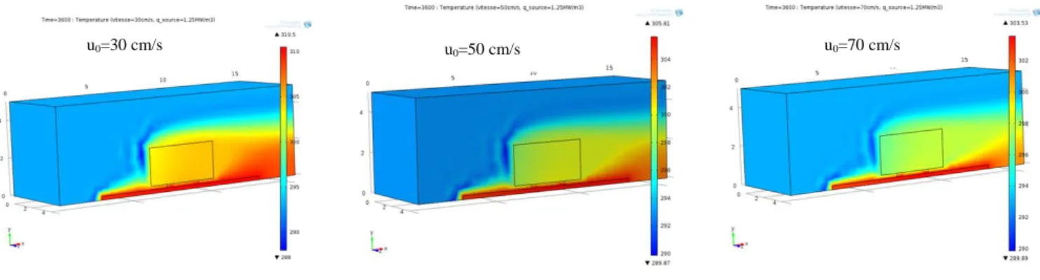
Figure 9 : 3D temperature distribution for (a) aluminum, (b) copper and (c) graphite, (d) comparison of temperature profiles for the three metals at the metallic foam-component interface.
Figure 10: 3D velocity distribution for (a) aluminum, (b) copper and (c) graphite, (d) comparison of velocity profiles for the three metals at the metallic foam-component interface.
(a) Aluminum (b) Copper
(c) Graphite
(a) Aluminum (b) Copper
C. Effect of the metal’s foam heat sink
The phenomenology of the heat transfer within the channel for the three types of metal’s foam heat sink is as follows: downstream of the channel and the top of the heat sink is almost at room temperature, the entire flux dissipated by the electronic component is transferred to the electronic plate on the one hand, and absorbed by the foam heat sink on the other hand, the flux is dissipated by the mixed conduction-convection heat transfer towards the air (heat transfer fluid) (figs 9.a, b and c). The phenomenology of the heat transport within the channel is identical for the three metals (aluminum, copper and graphite), the difference lies in the values of the temperatures. There are three areas: component-plate area, sink area and upstream-above channel area, each area is at a different temperature. For aluminum, the temperature distribution in the three zones is respectively 304 K, 299 and 294 K. for copper: 305 K, 300 and 292.5 K, and for graphite: 305 K, 298.5 and 293 K. The comparison of temperature profiles at the component-foam interface (figure 9.d) shows that the graphite foam is better in cooling followed by aluminum and copper foams.
Figures (10.a, b and c), the air velocity is average value at the entrance of the channel, low in the foam heat sink, and height above the foam. This behavior is almost identical for the three metals (aluminum, copper and graphite). At the median plane of the foam (Figure 10.d), the comparison of velocity profiles shows almost identical profiles. In the graphite foam, the speed is slightly higher than those in aluminum and copper.
IV. CONCLUSION
A CFD simulation of heat transfer and air flow through a channel equipped with an electronic component-plate system cooled by a metal foam heat sink was presented. The Darcy-Forchheimer-Brinkman model of airflow within a porous medium has been adopted from the literature. The COMSOL multiphysics software is used to solve equations and numerically simulate the studied system using the finite element method. The effects of the air velocity [20, 70] cm/s, the heat flux dissipated by the electronic component [1,25..1,7] MW/m3 and the nature of the foam used as dissipator (Aluminum, Copper and Graphite) on the phenomenology of the system are examined.
The following conclusions can be mentioned:
The adopted mesh consistency analysis proves that the CFD model made by COMSOL software generates the most efficient mesh, giving better and more accurate numerical results.
Under the conditions of a constant imposed heat flux and a constant air velocity at the inlet, three temperature zones can be distinguished: the highest zone is situated at the level of the electronic plate-component pair, the lowest zone is located in the lover of the canal, and that of average temperature is at the level of the metal foam heatsink, which plays the role of an absorber of calories dissipated by the component.
The hydrodynamic phenomenology of the flow under the conditions envisaged, shows that the speed is average in
lover of the channel at the entrance, weak at the level of the dissipator in foam, and strong above this last one. The effect of increasing the air velocity at the inlet of the
channel promotes heat transfer by convection at the dissipator and in air towards the channel, which promotes the cooling of the component electronic.
The effect of the flux increase is minimal on the thermohydraulic phenomenology of the channel provided with the electronic plate-component system with a metal foam dissipator.
NOMENCLATURE CF : friction coefficient (dimensionless)
Cp : heat capacity of fluid
df : fiber diameter
dp : pore diameter
H : height of foam block
hsf : convection heat transfer coefficient
K : permeability of the porous medium k : thermal conductivity
L : length of foam block Nux : local Nusselt number
Nusf : fluid-to-solid Nusselt number
p : pressure
Pr : Prandtl number (dimensionless) ppi : number of pores per inch Re : Reynolds number (dimensionless)
Redf : Reynolds number based on the fiber diameter
Redp : Reynolds number based on the pore diameter
qw : specific heat flux
T : temperature
Tw,x : local wall temperature
Ti : temperature entering foam
U : dimensionless velocity in the x-direction u : velocity component in the x-direction uD : Darcian velocity
ui : average velocity entering foam
v : velocity component in the y-direction V : dimensionless velocity in the y-direction W : width of foam sample
X, Y : dimensionless Cartesian coordinates x, y : Cartesian coordinates
Greek symbols ε : porosity ρ : density of fluid α : specific surface area ∆ : Change
: dynamic viscosity ν : kinematic viscosity
σ : surface area per unit volume of foam ϴ : dimensionless temperature
ϴw, x : dimensionless local wall temperature
Subscripts d : thermal dispersion f : fluid fe : fluid effective i : inlet s : solid se : solid effective w : wall REFERENCES
[1] Z. Dai, K. Nawaz, Y. Park, Q. Chen and A. M. Jacobi, A comparison of metal–foam heat exchangers to compact multilouver designs for air-side heat transfer applications, Heat Transfer Eng, 33 (1) ( 2012) 21–30.
[2] B. Boyd and K. Hooman, Air-cooled micro-porous heat exchangers for thermal management of fuel cells, Int. Commun. Heat Mass Transfer, 39 (2012) 363–367.
[3] C. Hutter, D. Büchi, V. Zuber and Ph. Rudolf von Rohr, Heat transfer in metal foams and designed porous media, Chem. Eng. Sci, 66 (2011) 3806–3814.
[4] Z. Wu, C. Caliot, G. Flamant and Z. Wang, Numerical simulation of convective heat transfer between air flow and ceramic foams to optimise volumetric solar air receiver performances, Int. J. Heat Mass Transfer, 54 (2011) 1527–1537.
[5] X. Ji, J. Xu and A. M. Abanda, Copper foam based vapor chamber for high heat flux dissipation, Exp. Therm. Fluid Sci, 40 (2012) 93–102. [6] Z. M. Wan, G. Q. Guo, K. L. Su, Z. K. Tu and W. Liu, Experimental
analysis of flow and heat transfer in a miniature porous heat sink for high heat flux application, Int. J. Heat Mass Transfer, 55 (2012) 4437–4441.
[7] C.Y. Zhao. 2012. Review on thermal transport in high porosity cellular metal foams with open cells, Int. J. Heat Mass Transfer 55. 3618–3632.
[8] S. Mancin, C. Zilio, A. Diani and L. Rossetto, Air forced convection through metal foams: Experimental results and modeling, Int. J. Heat Mass Transfer, 62 (2013) 112–123.
[9] A. Bhattacharya, V. V. Calmidi and R. L. Mahajan, Thermophysical Properties of High Porosity Metal Foams, Int. J. Heat Mass Transfer, 45 (2002) 1017-1031.
[10] M. S. Phanikumar and R. L. Mahajan, Non-Darcy natural convection in high Porosity metal foams, Int. J. Heat Mass Transfer, 45 (2002) 3781–3793.
[11] A. Haji-Sheikh and K. Vafai, Analysis of flow and heat transfer in porous media imbedded inside various-shaped ducts, Int. J. Heat Mass Transfer, 47 (2004) 1889–1905.
[12] A.R. Alvarez-Hernandez. Combined Flow and Heat Transfer Characterization of Open Cell Aluminum Foams, M.Sc. Thesis University of Puerto Rico, (2005).
[13] N. Dukhan, Correlations for the pressure drop for flow through metal foam, Exp. Fluids, 41 (2006) 665–672.
[14] W.J. Minkowycz and A. Haji-Sheikh, Heat transfer in parallel plates and circular porous passages with axial conduction, Int. J. Heat Mass Transfer, 49 (2006) 2381–2390.
[15] A. Kopanidis, A. Theodorakakos, E. Gavaises and D. Bouris, 3D numerical simulation of flow and conjugate heat transfer through a pore scale model of high porosity open cell metal foam, Int. J. Heat Mass Transfer, 53 (2010) 2539–2550.
[16] C. Chen, P. Huang and H. Hwang, Enhanced forced convective cooling of heat sources by metal-foam porous layers, Int. J. Heat Mass Transfer, 58 (2013) 356–373.
[17] M. Bai and J.N. Chung, Analytical and numerical prediction of heat transfer and pressure drop in open-cell metal foams, Int. J. Thermal Sciences, 50 (2011) 869–880.
[18] N. Dukhan and M. Ali, Strong wall and transverse size effects on pressure drop of flow through open-cell metal foam, Int. J. Thermal Sciences, 57 (2012) 85–91.
[19] P. Ranut, E. Nobilea and L. Mancini, High resolution microtomography-based CFD simulation of flow and heat transfer in aluminum metal foams, Applied Thermal Engineering, xxx (2013) 1– 11.
[20] N. Dukhan and K. Chen, Heat transfer measurements in metal foam subjected to constant heat flux, Experimental Thermal and Fluid Science, 32 (2007) 624–631.
[21] A. Bhattacharya, V.V. Calmidi and R.L. Mahajan, Thermophysical properties of high porosity metal foams, Int. J. Heat Mass Transfer, 45 (2002) 1017–1031.
[22] V.V. Calmidi, Transport phenomena in high porosity metal foams, PhD. Thesis, University of Colorado, Boulder, CO, (1998).
[23] V.V. Calmidi and R.L. Mahajan, The effective thermal conductivity of high porosity metal foams, ASME J. Heat Transfer, 121 (1999) 466–471.
[24] D.L. Koch, J.F. Brady, The effective diffusivity of fibrous media, AIChE J 32 (1986) 575–591.
[25] V.V. Calmidi and R.L. Mahajan, Forced convection in high porosity metal foams, ASME J. Heat Transfer, 122 (2000) 557–565.
[26] A. Zhukauskas, Heat Transfer from Tubes in Cross Flow, in: J.P. Hartnett, T.F.Irvine Jr. (Eds.), Advances in Heat Transfer, vol. 8, Academic Press, New York,(1972).
[27] E. Thomas and K. Karan, Methodology for determining volumetric convection coefficients in metallic foam monoliths coated with ceramic catalyst support, Thermal Issues in Emerging Technologies, ThETA 2, Cairo, Egypt, (2008).