HAL Id: hal-01737026
https://hal.archives-ouvertes.fr/hal-01737026
Submitted on 19 Mar 2018
HAL is a multi-disciplinary open access
archive for the deposit and dissemination of
sci-entific research documents, whether they are
pub-lished or not. The documents may come from
teaching and research institutions in France or
abroad, or from public or private research centers.
L’archive ouverte pluridisciplinaire HAL, est
destinée au dépôt et à la diffusion de documents
scientifiques de niveau recherche, publiés ou non,
émanant des établissements d’enseignement et de
recherche français ou étrangers, des laboratoires
publics ou privés.
Reliable navigation planning implementation on a
two-wheeled mobile robot
Pierre-André Crépon, Adina Panchea, Alexandre Chapoutot
To cite this version:
Pierre-André Crépon, Adina Panchea, Alexandre Chapoutot. Reliable navigation planning
imple-mentation on a two-wheeled mobile robot. The Second IEEE International Conference on Robotic
Computing, Jan 2018, Laguna Hills, California, United States. 2018, �10.1109/IRC.2018.00035�.
�hal-01737026�
Reliable navigation planning implementation
on a two-wheeled mobile robot
Pierre-Andr´e Cr´epon
ENSTA ParisTech, Palaiseau, France [email protected]
Adina M. Panchea
LIX, ´Ecole Polytechnique, Palaiseau, France [email protected]
Alexandre Chapoutot
U2IS, ENSTA ParisTech, Palaiseau, France
Abstract—Autonomous mobile robots must be equipped with appropriate planification and control navigation systems in order to obtain robust behaviours. This study aims at dealing with this kind of problems when implementing on a two wheeled mobile robot. The planning navigation system uses our previously proposed reliable and safe navigation planning algorithm based on the incremental sampling-based planning algorithm, e.g., the widely-used Rapidly-exploring Random Tree (RRT), while the control navigation level consists in a go to goal controller strategy. Through experiments, we demonstrate the usefulness of robust navigation planner in an autonomous navigation schemes, where uncertain localization has to be taken into account.
I. INTRODUCTION
One of the objectives in the field of the autonomous naviga-tion of mobile robots is the development of mobile platforms that robustly operate in complex or populated environments while offering various services without human interactions. A challenge for the autonomous navigation’s planner level is related to the guarantee of the system’s safety. To this end, in this study, we use a previously proposed reliable motion plan-ner algorithm [3] based on Rapidly-exploring Random Trees (RRT) principles [1], which covers the whole configuration space and easily integrates complex robot models, and solved in an interval analysis [2] framework. More precisely, we consider while planning, the uncertainties from a visual local-ization provided by camera, bounded with know bounds. For navigation control algorithms an interesting survey is proposed in [4], while in this study a go to goal strategy is used. Briefly, the main contribution of this paper is the implementation on a real mobile robot application of an navigation planner under DynIBEX1, while the visual localisation information is bounded with known bounds.
II. PROBLEMSTATEMENT
Context Given a mission, which consists in starting from an initial and a goal configurations provided by a visual sensor (camera) to the motion planning level, waypoints are computed and then sent to the controller level so that a mobile robot can reach the goal point while avoiding static obstacles.
Problem Given unique initial and goal positions, find collision-free paths and drive a mobile robot from the initial to the goal position.
1http://perso.ensta-paristech.fr/∼chapoutot/dynibex/
Figure 1. Autonomous navigation architecture
Experimental architecture: The mobile robot has to be driven in a two-dimensional static configuration space of size 1.2m × 1.8m × 2πrad, from an initial state to a desired one while avoiding polygons shaped obstacles. A brief description of the experimental navigation architecture is given in Fig.1
and it is as follows: First, the static configuration space, with free and non-admissible region subsets, is provided. Then, a QR code tracking package along with visual sensor (a camera), is used to specify the initial and final configurations. Then, for the given configuration space the planner will generate waypoints for a collision-free path and send it to the Arduino board via radio communication server based Xbee modules which will make the mobile robot reaching the final region subset.
Solution First we create a two-wheel mobile robot con-figuration which is localized by a visual sensor, receives the commands information via radio transmission from the navigation planning level sends sequence of control policy or waypoints given by the robust navigation planner, namely BoxRRT. Hence the mobile robot can reach to the desired configuration following the architecture illustrates on Fig. 1.
III. NAVIGATION PLANNING LEVEL
First the given initial configuration [sinit] is added to the
exploration tree G (Line 1). Then, a state [srand] ⊂ Sfree
is randomly chosen by the procedure random-box-GoalBias (Line 4). The nearest-neighbor procedure from Line 5 returns the closest vertex [snear] to [srand] in the tree G, according
the Hausdorff distance between two intervals metric d. The select inputprocedure provides a control input u = [v ω] ∈ [u], with v the linear and ω the angular speed. The control input is exhibited by using a go-to-goal principle by orienting the mobile robot towards the target and going straight ahead until it’s reaching the goal. Then, in the prediction procedure, the differential system which can the evolution of the mobile robot system: ˙s= f (s(t), u(t)) is integrated over a fix time interval ∆t with the initial condition [snear] and a constant
control input u (given at Line 6) and will result in a new state [snew] (Line 7). If it can be proved that all state values
along the trajectory between [snear] and [snew] lie in Sfree
being a collision free path, then the path between [snear]
and [snew] is considered reliable and [snew] is added to G
as a new vertex and connected to its parent [snear] though
the G.add-guaranteed-vertex procedure. Otherwise, [snew] is
not added to G. Lines 4 to 11 are repeated until a chosen number of iterations K is reached or until a path is found meaning [snew] = [sgoal], or most likely when [snew] ⊂ [sgoal].
Note that we have [sinit] = Hull(Sinit), [sobs] = Hull(Sobs) and
[sgoal] = Int(Sgoal) to ensure the soundness of the proposed
algorithm.
input : {stateinit, stategoal} ⊂ Sfree, ∆t ∈ R+, K ∈ N
output: G
1 G.init(stateinit), i ← 0; 2 repeat
3 staterand← random(i);
4 [snear] ← nearest-box-neighbor(G, [srand]);
5 [snew] ← new-box-state([srand], [snear], u, ∆t, [sgoal]); 6 if collision-free-path ([snear], [snew], u, ∆t) then 7 G.add-guaranteed-vertex([snew]);
8 G.add-guaranteed-edge([snear], [snew], u, ∆t); 9 return /0;
10 until i++ < MaxIter;
11 return G or Failure if no such path exists;
Algorithm 1: BoxRRT planner algorithm
IV. EXPERIMENTAL RESULTS
All simulations and experimental tests were performed on an Intel Core m7-6Y75 CPU at 1.20GHz×4. The used soft-ware for the BoxRRT planner consists in DynIBEX, while the middleware used for the experimentations consists in Robot Operating System (ROS).
The differential system which describes the evolution of the mobile robot is represented by the kinematic model of an unicycle robot type: ˙x= v cos θ , y˙= v sin θ , θ = ω ,˙ with (x y) the position and θ the orientation w.r.t. a frame attached to the environment. The control input u = [v ω] is represented by the linear v ∈ [−0.4; 0.4] m/s and the angular δ ∈ [−10; 10] rad/s velocities respectively. The latter values were determined experimentally.The reported CPU values are the mean of the CPU obtained after 100 iterations. Although, the obtained CPU performances for all three investigated configurations
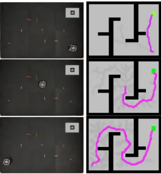
Figure 2. Planning visualization
remains less than 70s. For all trials the navigation planners found waypoints for free-collision paths. The purpose of this study is to introduce the BoxRRT navigation algorithm for real application and to presents the advantages of this planner usage, when using localisation information provided by visual means and which depends on QR code can be perturbed due to some external perturbations. In the latter hypothesis and if one utilises the navigation planners provided by the OMPL [5] the mobile robot needs to be physically placed at the precise desired location. While for the BoxRRT planner an imprecise initial position can be fixed and a tube is provided without no user intervention. Moreover, as long as the robot stays inside the provided tube of trajectories we are certain that the robot achieves the task with no collision.
V. CONCLUSIONS AND FUTURE WORKS
In this study, our previously proposed BoxRRT navigation planner is implemented on a real mobile robot application for the first time. In future work we plan to provide the robust and reliable motion planner based on an online library.
ACKNOWLEDGMENT
This work was supported by DGA MRIS. REFERENCES
[1] S. M. LaValle. Rapidly-exploring random trees: a new tool for path planning. Technical report, Iowa State University, 1998.
[2] R. E. Moore. Interval Analysis. Prentice-Hall, 1966.
[3] A. M. Panchea, A. Chapoutot and D. Filliat. Extended Reliable Robust Motion Planners. In CDC, 2017, to appear.
[4] B. Paden, M. Cap, S. Z. Yong, D. Yershov, E. Frazzoli A Survey of Motion Planning and Control Techniques for Self-Driving Urban Vehicles. IEEE Transactions on intelligent vehicles, 1(1):33–55, 2016. [5] I.A. S¸ucan, M. Moll and L.E. Kavraki. The Open Motion Planning