Any correspondence concerning this service should be sent
to the repository administrator:
tech-oatao@listes-diff.inp-toulouse.fr
This is an author’s version published in:
http://oatao.univ-toulouse.fr/22441
Official URL
DOI :
https://doi.org/10.1109/HPCS.2018.00050
Open Archive Toulouse Archive Ouverte
OATAO is an open access repository that collects the work of Toulouse
researchers and makes it freely available over the web where possible
To cite this version:
Motie, Yassine and Belghache, Elhadi and Nketsa,
Alexandre and Georgé, Jean-Pierre Interoperability based Dynamic Data
Mediation using Adaptive Multi-Agent Systems for Co-Simulation. (2018)
In: 16th International Conference on High Performance Computing and
Simulation (HPCS 2018), 16 July 2018 - 20 July 2018 (Orléans, France).
Yassine Motie
LAAS-IRIT, University of Toulouse
Toulouse, France Yassine.Motie@irit.fr
Elhadi Belghache
IRIT, University of ToulouseToulouse, France Elhadi.Belghache@irit.fr
Alexandre Nketsa
LAAS-CNRS Toulouse, France Alex@laas.frJean-Pierre Georg´e
IRIT, University of ToulouseToulouse, France Jean-Pierre.George@irit.fr
Abstract—A co-simulation is the coupling of several simulation tools where each one handles part of a modular problem which allows each designer to interact with the complex system in order to retain its business expertise and continue to use its own digital tools. For this co-simulation to work, the ability to exchange data between the tools in meaningful ways, known as Interoperability, is required.
This paper describes the design of such interoperability based on the FMI (Functional Mock up Interface) standard and a dynamic data mediation using adaptive multi-agent systems for a co-simulation. It is currently being applied in neOCampus, the ambient campus of the University of Toulouse III - Paul Sabatier. Index Terms—Interoperability; Mediation; Co-Simulation; Adaptive Multi-Agent Systems;
I. INTRODUCTION
A co-simulation is a set of interacting simulation units, each one needs Input data and produces Output data. A simulation unit is the composition of a simulator (solver) with a dynamic system (model of a real environment characterized by a state and a notion of evolution rules). The outputs of a simulation unit might be the inputs of others. The progress of the simulated time in each simulation unit is controlled by an orchestrator, called also a master algorithm. This last one, based upon a co-simulation scenario, moves data from outputs to inputs. Therefore, the matching process between the inputs and outputs is difficult especially in open cyberphysical envi-ronments where components1join and leave the co-simulation
on the fly, like in the neOCampus operation of the University of Toulouse III - Paul Sabatier [1].
[2] described a new co-simulation framework interoper-ability based FMI (Functional Mock up Interface) standard for the structural interoperability part and data mediation for semantic interoperability part. In this work, we propose a
dynamic mediation for adaptation of the data which allows to go further towards the development of global and open simulation environment. The idea is to take advantage of the self-adaptation and openness capability of Adaptive Multi-Agent Systems (AMAS) through DREAM [3] and AMOEBA
1A component is an autonomous deployment entity which encapsulates the
software code showing only its interfaces
[4] (see section III) which need no knowledge about the data and their application field.
The paper is organized as follows, firstly we present the interface used to reach a structural interoperability, then the Collective Artificial Intelligence used to achieve a semantic interoperability, in order to build our co-simulation framework. We continue with the application of the latter neOCampus operation and give a conclusion and future work.
II. STRUCTURALINTEROPERABILITY OF THE
COMPONENTS A. Interoperability
Interoperability can be defined as the ability of two or more entities to communicate and cooperate despite differences in the implementation language, the execution environment, or the model abstraction [5]. Two types of interoperability have been distinguished, process-oriented interoperability that aims to adapt software code using overload and dynamic link mechanisms, and data-oriented (or object-oriented) interop-erability, which aims to adapt data (by coercion mechanism). We focused on the last one, which leads us to distinguish two main levels of interoperability. The structural one, which is discussed in this part, is supported by middleware architects and vendors who are trying to establish different interopera-tional standards. The substantive (or semantic) interoperability (contents meaning) that makes our components understand each other correctly and co-simulate effectively.
Among the different standards of simulation interoperabil-ity, the two most well known are HLA (High-Level Architec-ture) and FMI. In HLA federate (components) are connected to a central Run-Time Infrastructure (RTI). In FMI, components are FMUs (Functional Mock up Unit) and a master must be written to transfer data between FMUs and order the execution of a time step. To avoid the obligation imposed in HLA to use RTI libraries from the same provider and usually of the same version in order for applications to interoperate, we chose the standard FMI [6]. FMI uses a master-slave architecture as a simulation interoperability standard. FMI is a standard which minimizes the customization of the exported model. It is an independent tool that facilitates the exchange of models
Interoperability
based Dynamic Data Mediation
using
Adaptive Multi-Agent Systems
for
Co-Simulation
between different tools and which therefore reduces the effort of integration by proposing approaches that are specific to it.
B. FMI Functional Mockup Interface
FMI is a standard interface for the solution of coupled time dependent systems, consisting of continuous or discrete time subsystems. It provides interfaces between master and slaves and addresses both data exchange and algorithmic problems. Simple and sophisticated master algorithms are supported. However, the master algorithm itself is not part of FMI for co-simulation and has to be defined [7] [8]. FMI supports different working modes, particularly: (1) model exchange (when a modeling environment can generate C code of a dynamic system model that can be utilized by other modeling and simulation environments), and (2) co-simulation (when an interface standard is provided for coupling simulation tools in a co-simulation environment)
The use of FMI can be summarized in 4 steps:
• The design step: The package of the model of simulation in one component FMU embedding the modeling, and transformation (publication of the FMU which contains a xml file and the model code or its file). The main challenge is to fill-up the gap between the semantics of FMI and the semantics of the source formalism of the various calculation models (state machines, discrete event, data flow or timed automata) [9].
• The composition step: The model of the subsystem is joined to the complex system by establishing the connection graph of the simulation components.
• The deployment step: The FMUs are made available to
the slave simulators. This can be made offline (manually by the user) or online (automatically by the master and where the user specifies in which network the instances of the FMUs are transferred).
• The simulation step: The master is responsible for the
life cycle of FMUs instances during the execution of the simulation.
C. Co-Simulation Steps
In our previous work [2] we designed a co-simulation framework interoperability performing a co-simulation based on a black box component approach. We defined communi-cation ports and guaranteed the possibility of connection by respecting data types and the direction of the ports following the FMI standard. We designed a mediation approach to ensure the unambiguous information exchange. We noticed that the semantic interoperability based on mediation was integrated to our framework in an ad-hoc way. This took a heavy work investment as each component needed a hand-made encapsulated mediator.
We now want to automate this process using DreAMoeba, the extension of DREAM2 with AMOEBA3 (see III-C), as a
black box component in the co-simulation framework, which
2DREAM stands for Dynamic data Relation Extraction using Adaptive
Multi-agent system
3”AMOEBA”stands for Agnostic MOdEl Builder by self-Adaptation
is able to link dynamically correlated inputs and outputs and hence to continuously adapt the structural interoperability and carry out the semantical one.
In the next section, we present both DREAM and AMOEBA two collective artificial intelligence based tools.
III. COLLECTIVEARTIFICIALINTELLIGENCE FOR
SEMANTICINTEROPERABILITY
In this section, we present the tools used to achieve our new semantic interoperability and the theory behind them.
A. Adaptive Multi-Agent Systems Theory
Both DREAM and AMOEBA rely on a bio-inspired col-lective artificial intelligence (Adaptive Multi-Agent Systems), defined as follows:
1) Multi-Agent Systems: A Multi-Agent System (MAS) [10] is defined as a system composed of autonomous agents which pursue individual objectives and which interact in a common environment to solve a common task. The autonomy of an agent is a fundamental characteristic: an agent is capable of reacting to its environment and acts from its own decision, relying only on a limited and localized knowledge of the environment, using a set of skills and tools.
2) Self-Adaptive Multi-Agent Systems: A self-Adaptive Multi-Agent System (AMAS) is a MAS able to adapt itself: adjust itself, organize itself, heal itself, etc. [11] to remain in a well-functioning state after a perturbation. It relies on the fact that the agents do not follow a global directive towards the solving of the problem but collectively build this solving. This produces an emergent [12] problem solving process.
B. Dynamic Data Relation Extraction using AMAS
DREAM2[3] is an adaptive multi-agent system that extracts
relations between data streams, on the fly, based on their dynamics correlation. DREAM is able to find data streams that evolve in the same way, even if there is a time delay between them, thanks to a new correlation metric called Dynamics
Correlation, which allows to study (perceive and evaluate) data dynamics4 by combining a conventional statistical analytics
tool and a new physical analytics tool.
the statistical analytics tool is an incremental version of Pearson’s correlation coefficient r [13], defined as follows:
r(A, B) = Pn i=1(aibi) − n ¯A ¯B nσAσB (III.1) ¯ Ai= Si
i with Si= Si−1+ Ai, S0= 0 (III.2) σAi=
Qi
i − ¯A
2
i with Qi= Qi−1+ A2i, Q0= 0 (III.3)
Where,
- A, B are two variables (data features). - ¯X is the mean of X.
- σX is the standard deviation of X.
- n is the number of data points (values).
4Dynamics means the behavior or the evolution, in other words changes
The new physical analytics tool, called Phase Space
Simi-larity metric, is a comparison between two data streams dy-namics (evolution) using their dydy-namics abstraction, the Phase
Space. This metric is given with the following equations:
(psxAi, psyAi) = (Ai− Ai−1, Ai+1− Ai) (III.4)
P SA= {(psxAi, psyAi), ∀i ∈ [1, n − 1]} (III.5)
LP SD(Ai, Bi) = e−0.5( √|psx Ai−psxBi|−√|psyAi−psyBi|) 2 (III.6) LP SS(Ai, Bi, m) = Pi j=i−m+1LP SD(Aj, Bj)2 m , m≥ 1 (III.7)
The Dynamics Correlation metric is combination of the two previous metrics according to the following procedure:
Algorithm 1: Dynamics Correlation
1 if LP SS2≥ 0.7 and P artial r2≥ 0.01 then 2 return M ax(LP SS2, r2); //it is a true Dynamics
Correlation
3 if LP SS2≥ 0.7 and P artial r2<0.01 then 4 return -1; //it is a false Dynamics Correlation 5 if LP SS2≥ 0.7 and P artial r2≥ 0.01 then 6 return 0; //it is not a Dynamics Correlation
For a system of n inputs, it takes n(n−1)2 calls of the dynamics correlation tool to examine all the possible relations, which corresponds to a temporal complexity of O(n2) if
computed sequentially or a spatial complexity if computed in the same time, in either ways, this high complexity prevents the system to scale up.
Thence, for the sake of designing a component that pro-duces a dynamic graph model of the data relations on the fly, DREAM incorporates the dynamics correlation into an AMAS to focus only on the most probably correlated data and therefore reduces the computing power and the time to find all the data relations.
C. Agnostic MOdEl Builder by self-Adaptation
AMOEBA3[4] is composed of agents that build an agnostic
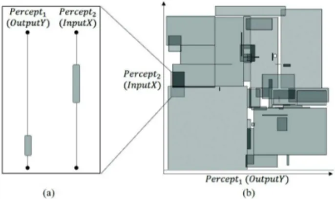
(without knowledge of the meaning) model of AMOEBA inputs, or ”percepts”, on the fly. These agents, called contexts, can be summarized as sets of percepts data ranges wherein each data point from one percept range corresponds to the data in all the other percept ranges (see figure1-a). All the context agents constitute a mapping of co-occurring data in the whole data space (see figure1-b). Moreover, a context agent has a confidence proportional to its percepts data co-occurring frequency.
We use AMOEBA, as an unsupervised learner5, to provide
a data translation function (described in IV-B). Consequently, the more inputs and data AMOEBA gets the higher is the
5Learns by itself without an expert telling the correctness of the learning
result (feedback)
Fig. 1: An example of AMOEBA context agents. (a) A context agent and its inputs ranges. (b) The mapping of a two dimensional data spaces (graphical representation of the context agents)
confidence in the model accuracy. This translation function provided by AMOEBA insures the semantical interoperability of the data dynamically correlated by DREAM. This process is explained in the next section.
IV. DYNAMICDATAMEDIATION
In our previous work, we set up an individual mediator for each component, using a context mediation, to make the subsystems understand each others data. However, the creation and maintenance of such mediation model, as a standard used by all the subsystems, requires considerable amount of time and efforts. This mediation model leads to define three types of integration rules:
1) constraint rules that reduce the objects to be considered according to predicates,
2) merge rules that aggregate instances of classes of similar, 3) and join rules that combine information from multiple object
classes based on one or more common properties. We distinguished two types of mediation:
1) Schema mediation which provides better extensibility and often better scalability (object interfaces, rule-based lan-guage).
2) Context mediation seeks to discover data that is semantically close, it is able to locate and adapt information to ensure complete transparency. We can therefore take advantage of the robustness of the mediation schema approach and combine it with the semantic approximation techniques of context mediation. This semantic mediation will be used to correlate, aggregate and dispatch data with respect to the control that we want to enforce on data produced or consumed.
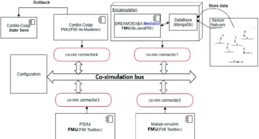
Therefore, we extend our co-simulation framework with a new component for dynamic data mediation, called
”DreAMoeba”(see figure 2), operating as follows:
1) Use DREAM to link the subsystems dynamically, each link is described with an (Output, Input) couple (IV-A).
Fig. 2: Co-simulation Architecture using DreAMoeba mediator 2) For each data couple query, use AMOEBA to translate the
data form Output to Input (IV-B).
A. Dynamic Subsystem-to-Subsystem Graph Model
A Subsystem-to-Subsystem Graph Model (SSGM) is a con-nection graph between the subsystems, encapsulated in FMUs, which displays their communications bridges and therefore describes which outputs from one subsystem are connected to the inputs of another.
When one wants to start a co-simulation, he has to describe manually SSGM at the composition step. This is a hard and time consuming task considering, in the one hand, that it requires some expert-domain knowledge about the data and, in the other hand, when dealing with real large cyberphysical environments the number of available data is high. Moreover, once this SSGM is established, it can’t be modified during the simulation step for the sake of an interactive and dynamic integration of a new subsystem. This requires a shut down of the system and then an update of the SSGM with new subsystems and finally a restart of the co-simulation.
Hereafter, we describe how the use of DREAM can reduce, and ultimately get ride of, the human interaction with the co-simulation framework. For a better understanding, we virtually split DREAM’s behavior in two.
1) Initialization Behavior: All the salves inputs and outputs (figure 3-a) are considered as input data streams for DREAM which builds the dynamics correlations graph for the data streams (figure 3-b). In addition, we extend DREAM’s agents with a filtering behavior in order to discard the links (dynamics correlations) between the data streams of the same subsystem and links between data streams of the same type (input-input, output-output), because such links are irrelevant to build a subsystem-to-subsystem graph model (figure 3-b). Besides, we leave to the users the choice, if desired, of a specific subsystem to which they want to link, resulting in the
subsystem-to-subsystem graph model(figure 3-c).
2) Nominal Behavior: DREAM is able to handle large amounts of data streams leading to a huge number of links and consequently to ({output1, output2. . . outputN}-input) couples. In such situations, where one input can be linked to several outputs, DREAM keeps only the strongest link (link with the highest Dynamics Correlation metric value). As you can see in figure 3, the input InB3 is linked with OutA2, OutB1, OutC1 and OutC2. However, DREAM discards (OutB1-InB3) because they are of the same subsystem B. Moreover, DREAM discards (OutA2-InB3) and (OutC2-InB3) as they are weaker than (OutC1-InB3) regarding their Dynamics Correlation strengths. In addition, DREAM is self-adaptive to its environment (see III-B). In other words, it can update the SSGM on-the-fly. This continuous adaptation allows our co-simulation framework to cope with changes occurring in the cyberphysical environment. These changes are:
• the evolution of the existing subsystems inputs and outputs. DREAM removes links between inputs and outputs of different subsystems that are not dynamically correlated anymore and links the newly dynamically correlated ones.
• the arrival of new subsystems. DREAM provides, for the
new subsystems, links with existing subsystems and re-places previous links with stronger ones, if found.
• and most importantly, the departure of an already present subsystem in the co-simulation. In this case, DREAM finds, if they exist, other relations to replace the links destroyed by the subsystem departure from the co-simulation.
B. Data Translation using AMOEBA
By virtue of its genericity6, DREAM doesn’t process high-level semantics i.e. it doesn’t handle the meaning of the data like temperature, luminosity, CO2, energy consumption, etc. Hence, it finds heterogeneous links (luminosity-temperature, humidity-CO2. . . ) which is problematic knowing that data can have different domains and different semantics.
Fig. 3: Example of Subsystem-to-Subsystem Graph Model building with DREAM.
Thus, we combine DREAM with a second self-adaptive artificial intelligence, called ”AMOEBA” (see III-C), able to act as a translator between heterogeneous data couples
(Output, Input). This translator is a matching function between the Output data and the most probable Input data. Ideally, we would have a homogeneous mapping of the data space such that there are context agents, with only one data point per each percept (AMOEBA input) range, that cover all the data space. However in cyberphysical environments some data are missing or noisy, which leads to heterogeneous mapping with overlapping context agents of different sizes (see figure1-b). Therefore, AMOEBA has to reduce the set of the contexts that map the Output data, using if needed, the other percepts data and their confidence, then producing the Input data by returning the mean value of all the remaining context Input ranges, as follows:
C. Model Calibration
As we described it in subsection IV-A, DREAM continu-ously updates the links of the SSGM in order to keep only the best ones. These updates are more frequent during DREAM’s initialization phase until it stabilizes. For this reason, we need a model calibration phase to generate a first more stable SSGM before introducing the subsystems in the co-simulation.
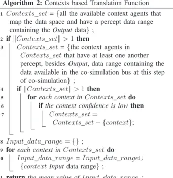
Algorithm 2: Contexts based Translation Function
1 Contexts set ={all the available context agents that
map the data space and have a percept data range containing the Output data} ;
2 if kContexts setk > 1 then
3 Contexts set ={the context agents in
Contexts set that have at least one another percept, besides Output, data range containing the data available in the co-simulation bus at this step of co-simulation} ;
4 ifkContexts setk > 1 then
5 for each context in Contexts set do 6 if the context confidence is low then 7 Contexts set=
Contexts set− {context};
8 Input data range= {} ;
9 for each context in Contexts set do
10 Input data range = Input data range∪
{context Input data range} ;
11 return the mean value of Input data range ;
Similarly, AMOEBA requires a calibration in order to provide a translator model used for the dynamic data mediation.
This model calibration, can be seen as the training of a machine learner. Thus, we need a database containing, for each subsystem, the data used by its input and provided by its outputs during a test run, to generate a first SSGM and translator model then start the co-simulation with them.
V. NEOCAMPUSUSECASE
We took the neOCampus operation [1] as use case because it’s considered as a smart city where several data streams come from heterogeneous sensors placed inside and outside the buildings (CO2, temperature, humidity, luminosity, human presence, energy and fluid consumption, ...). It’s also a com-plex system as each expert interacts with data differently using a specific field within simulation to design the campus of the future, that eases campus users life, reduces the ecological impact by controlling energy and fluids consumption.
A. Different Simulators Used
We took as example some simulators using different kinds of data. One, implemented in Matlab Simulink, works on reducing the energetic consumption using a black box neural network heat pump model and ensuring a comfortable desired temperature in the rooms by heating and cooling when it is necessary. It requires from sensors the Electric power (Kw) and the indoor temperature and provides the optimal temperature with a specific time step.
Another, implemented with the Powersims toolbox of simulink [14] using Maximum Power Point Tracking makes it possible to follow the maximum power point of a non-linear electric generator. It requires the values of the Photovoltaic
current and the voltage and provides a Converter control setpoint
Another, implemented in Cooja Contiki7 [15], which
al-lows large and small networks of Contiki nodes to be sim-ulated in order to evaluate the performances (energy, delays) of IoT networks, using the protocol CCN (Content Centric Networking) applied on a network of sensors. This simulator, developed in C++ under linux OS, requires interest (requests sent by users containing the name of the data such as the temperature) and provides the value of this data.
As the collection of sensors data is stored in a NoSQL database (mongodb), we use them as a training set for DreAMoeba which is a java simulation made to mediate data. It requires data provided from the other components to make correlations and translations then, provides the right dynamically linked data couples, as described in section IV and illustrated with a use case scenario (see V-C). We have also built a knowledge base from sensors data that provides real-time data and relationship between them in order to build later an ontology on which to map the data provided.
B. Co-simulation engine
The design approach of neOCampus is necessarily scalable and adaptive, which directs our work towards the development of global and open simulation environment. As we said before, we adopted the component approach and described the general FMI’s way of working II-B. This last follows a master-slave architecture, and we mentioned that:
• a master algorithm needs to be defined in order to syn-chronize the simulation of all subsystems and to proceed in communication steps,
• the data exchange between subsystems is connected via
MPI, TCP/IP, Sockets,
• the mapping between outputs to inputs has to be initialized. We used CosiMate (a co-simulation environment), as in [2], to save the efforts of dealing with synchronization between our subsystems (avoiding the definition of a master algorithm). To perform this integration, CosiMate provides libraries to make the customization easier. The libraries contain (1) I/O ports compiled and described for the simulator/language used. (2) I/O ports description. This description depends on the environment in which the ports are to be used: for example, a header file for C/C++ language is provided.
CosiMate provides synchronization methods that take into account the different behaviors of the languages and the simulators used. Thus, when a simulation is performed on a network, CosiMate considers the intrinsic constraints of the communication medium. CosiMate self-adapts to the network configuration, offering a co-simulation based on a multi-client multi-server to avoid unnecessary communications be-tween simulators instantiating local routers for each computer in the co-simulation. Thereby, Cosimate manages access to the co-simulation bus, used in this distributed model as a
7an operating system for networked, memory-constrained systems with a
focus on low-power wireless Internet of Things devices
communication protocol. It coordinates the data by the bus controller. It also handles the integration of time [16] which is different between embedded software systems, hardware and the surrounding environment.
In our case and according to the different simulators mentioned previously, we constructed an FMU’s component for each one either by using FMI toolbox like for MAT-LAB/Simulink, or a wrapper using FMI Library from Modelon for the simulator using Contiki. We made it easy to connect all the simulators knowing that for example, Simulink is supported by Cosimate but Contiki is not. However, the CosiMate FMI connector can load and run all FMI models compatible with FMI 1.0/2.0 for the co-simulation mode. As we said before, each of our FMU files is a zip file that contains a file named modelDescription.xml and one or more platform-dependent shared libraries. The XML files are used to describe how a model running in a simulation environment is connected to the CosiMate bus. We should mention that CosiMate allows execution in the native simulation environment, users can easily work in their familiar environment controlling, debugging, and monitoring simulations as if they are running in a stand alone mode integration. We can also use remote procedure: if the model is to be run on a remote machine. The CosiMate Spy tool is used to monitor and control the co-simulation components and processes. It acts as a reader of the CosiMate bus without modifying data exchanges or simulations synchronization during the co-simulation.
C. DreAMoeba Mediator
One of the problems encountered is the mediation part, since we want to achieve a semantic interoperability we used DreAMoeba (see IV). In order to grasp how it works, let’s take the following neOCampus co-simulation environment:
• a room equipped with several sensors (luminosity, humidity, co2, presence detection, heaters energy consumption).
• Matlab Simulink (see V-A) for optimizing the temperature and electric power consumption in the room.
As described in IV-C, we first calibrate DreAMoeba, which leads to discover the (room luminosity, Matlab Simulink
tem-perature input)and (room heaters energy consumption, Matlab
Simulink electric power input) couples. The latter couple is quite understandable since its Output and Input are about the same entity, the electric power used for heating the room. However, the former is less understandable considering, at first glance, their semantic dissimilarity. Nonetheless, DreAMoeba analyses the data deeper than what human hypothesis allow by studying their dynamics correlation mainly through their
phase spaces8. So, as you can see in figure 4 the two phase
spaces are similar, meaning the luminosity and the temperature behave fairly in the same way.
The data translation (IV-B) insured by AMOEBA for the (room luminosity, Matlab Simulink temperature input) is de-scribed in example algorithm 3.
Fig. 4: Luminosity and temperature data recorded by neO-Campus sensors during one week.
Algorithm 3: Example of the data translation on the toy neOCampus use case
1 if Luminosity≥ 20 then
2 AMOEBA returns a unique temperature as a result
of the homogeneous mapping of the data space when Luminosity≥ 20.;
3 In other words, each Luminosity data≥ 20
corresponds to a single temperature data ;
4 if Luminosity <20 then
5 Several temperatures are possible and according
to the data translation function (IV-B) AMOEBA return the mean temperature ;
For the sake of a more accurate translation, we add to AMOEBA one or more new percepts from the data Outputs available in the co-simulation environment. For example, by adding only the humidity percept to AMOEBA, it creates a third dimension to the data space, which allows AMOEBA to reduce the number of contexts that cover the temperature data and thus AMOEBA returns only one temperature data. To sum up, the more AMOEBA has percepts the higher is the data space dimension, that leads to less overlapping context agents and in consequence the more accurate is the data mediation.
VI. CONCLUSION ANDFUTUREWORK
Our architecture has been implemented and our modeling works well: we took as example the 4 simulators and used FMI for co-simulation in order to generate a slaves FMUs and solve the structural problems. Our DreAMoeba component which is used to ensure the mediation, in order to achieve the semantic interoperability, was encapsulated using JavaFMI. It is necessary to mention that our framework allows the integration of all types of simulators, knowing that Cosimate allows the co-simulation between FMI and also non-FMI models. Simulators which are not supported by Cosimate are wrapped as an FMUs components in order to plug them to our cosimate bus.
DREAM, as a black box, offers openness and self-healing features (make new connections and replace lost connections on the fly) to our co-simulation framework when combined
with an self-adaptive data translator will provide autonomous semantic interoperability.
Furthermore, these new features, without taking into account the semantic aspect through the data translation, can be applied independently to improve the current tools relying on FMI by (semi-)automatize the linking process between the slaves inputs and outputs. Moreover we would like, as future work, to approach semantic interoperability using ontology for the comparison purposes
VII. ACKNOWLEDGEMENT
We thank the Occitanie Region and the neOCampus oper-ation [1], which provided the funding and the testing ground in order to achieve this work.
REFERENCES
[1] M.-P. Gleizes, J. Boes, B. Lartigue, and F. Thi´ebolt, “neocampus: A demonstrator of connected, innovative, intelligent and sustainable cam-pus,” in International Conference on Intelligent Interactive Multimedia Systems and Services. Springer, 2017, pp. 482–491.
[2] Y. Motie, A. Nketsa, and P. Truillet, “A co-simulation framework interoperability for Neo-campus project (regular paper),” in European Simulation and Modelling Conference (ESM), Lisbon, 25/10/2017-27/10/2017. EUROSIS, 2017.
[3] E. Belghache, J.-P. Georg´e, and M.-P. Gleizes, “DREAM: Dynamic data Relation Extraction using Adaptive Multi-agent systems (regular paper),” in IEEE International Conference on Digital Information Management (ICDIM). IEEE, 2017.
[4] N. Verstaevel, J. Boes, J. Nigon, D. D’Amico, and M.-P. Gleizes, “Life-long Machine Learning with Adaptive Multi-Agent Systems (regular paper),” in International Conference on Agents and Artificial Intelligence (ICAART), vol. 2. SciTePress, 2017, pp. 275–286.
[5] H. Kohar, P. Wegner, and L. Smit, “System for setting ambient param-eters,” Sep. 10 1996, uS Patent 5,554,979.
[6] T. Blochwitz, M. Otter, M. Arnold, C. Bausch, H. Elmqvist, A. Jung-hanns, J. Mauß, M. Monteiro, T. Neidhold, D. Neumerkel et al., “The functional mockup interface for tool independent exchange of simulation models,” in Proceedings of the 8th International Modelica Conference; March 20th-22nd; Technical Univeristy; Dresden; Germany, no. 063. Link¨oping University Electronic Press, 2011, pp. 105–114.
[7] M. Consortium et al., “Functional mock-up interface for co-simulation,” Accessed March, vol. 1, p. 2013, 2010.
[8] O. Enge-Rosenblatt, C. Clauß, A. Schneider, and P. Schneider, “Func-tional digital mock-up and the func“Func-tional mock-up interface-two comple-mentary approaches for a comprehensive investigation of heterogeneous systems,” in Proceedings of the 8th International Modelica Conference; March 20th-22nd; Technical Univeristy; Dresden; Germany, no. 063. Link¨oping University Electronic Press, 2011, pp. 748–755.
[9] S. Tripakis, “Bridging the semantic gap between heterogeneous model-ing formalisms and fmi,” in Embedded Computer Systems: Architectures, Modeling, and Simulation (SAMOS). IEEE, 2015, pp. 60–69. [10] G. Weiß, Multiagent Systems, A modern Approach to Distributed
Arti-ficial Systems. MIT Press, 1999.
[11] G. Di Marzo Serugendo, M.-P. Gleizes, and A. Karageorgos, Self-organising Software: From Natural to Artificial Adaptation. Berlin, Heidelberg: Springer Berlin Heidelberg, 2011.
[12] P. A. Corning, “The re-emergence of emergence, and the causal role of synergy in emergent evolution,” Synthese, vol. 185, no. 2, pp. 295–317, Mar. 2012, wOS:000303530600009.
[13] B. E. Cooper, “Correlation and Function Fitting,” in Statistics for Experimentalists. Elsevier, May 2014, pp. 206–212.
[14] S. Khader, A. Hadad, and A. A. Abu-Aisheh, “The application of psim & matlab/simulink in power electronics courses,” in Global Engineering Education Conference (EDUCON). IEEE, 2011, pp. 118–121. [15] A. Dunkels, B. Gronvall, and T. Voigt, “Contiki-a lightweight and
flexible operating system for tiny networked sensors,” in Local Computer Networks. IEEE, 2004, pp. 455–462.
[16] S. Yoo and K. Choi, “Optimistic timed hw-sw cosimulation,” in in Proc. of APCHDL’97. Citeseer, 1997.