OATAO is an open access repository that collects the work of Toulouse
researchers and makes it freely available over the web where possible
Any correspondence concerning this service should be sent
to the repository administrator:
[email protected]
This is an author’s version published in:
http://oatao.univ-toulouse.fr/25089
To cite this version:
Boisson, Marylou
and Legras, Laurent and Andrieu, Eric
and Laffont,
Lydia
Role of irradiation and irradiation defects on the oxidation first stages
of a 316L austenitic stainless steel. (2019) Corrosion Science, 161. 108194.
ISSN 0010-938X
Role of irradiation and irradiation defects on the oxidation first stages of a
316L austenitic stainless steel
M. Boisson
a,b, L. Legras
b, E. Andrieu
a, L. Laffont
a,⁎aCIRIMAT, Université de Toulouse, CNRS, ENSIACET, 4 Allée Emile Monso, BP 44362, 31030, Toulouse Cedex 4, France bEDF R&D, EDF Lab Les Renardières – MMC, Avenue des Renardières – Ecuelles, 77818, Moret sur Loing, France
A R T I C L E I N F O Keywords: A. Stainless steel B. TEM B. STEM C. Oxidation A B S T R A C T
The role of irradiation and irradiation defects on the oxidation first stages of 316 L alloy was investigated. A sample with both a proton pre-irradiated and an unirradiated area was exposed to a simulated PWR environment during 24 hours. Irradiation defects and Radiation Induced Segregation at grain boundary and on irradiation defects were characterized and quantified and their effect on the oxidation was evaluated. Irradiation affects the morphology, thickness and chemistry of the oxide layers formed. It enhances the oxidation kinetic and induces the formation of an inner oxide richer in chromium. Defects induced by irradiation act as preferential nucleation sites.
1. Introduction
Since the 316 L alloy possess a high corrosion resistance thanks to the formation of a thin oxide film when exposed to aqueous solutions, it is currently used as a constituent for the baffle to former bolts in French Pressurised Water Reactors (PWRs). These bolts are subjected to a heavy neutron irradiation at temperatures ranging from 300 °C to 380 °C. In such conditions the bolts are simultaneously exposed to a corrosive environment at a high temperature and under mechanical stresses but also to the neutron flux emitted by the reactor core. This can lead to the cracking of a few bolts by a degradation mechanism called Irradiation Assisted Stress Corrosion Cracking (IASCC). IASCC is a major concern for the maintenance of nuclear power plants and a complex phenomenon. Irradiation is providing an enhancement of the susceptibility of the material to Stress Corrosion Cracking (SCC). Since the rupture of the oxide film formed is the first step in the SCC corrosion process, the nature, structure and chemistry of the oxide formed are key parameter to better understand and predict SCC initiation. It is there-fore of primary concern to study the influence of irradiation on the oxide formed on top of austenitic stainless steels.
In the literature, the oxide formed on austenitic stainless steel ex-posed to PWR media is reported to be duplex and of spinel structure (M3O4) [1–5]. The inner oxide layer is chromium rich, protective and described as a mixed iron/chromium spinel ((Ni,Fe)Cr2O4) while the outer oxide is found to be crystallites of geometric shapes of magnetite (Fe3O4). Many authors observed a nickel enrichment below the metal/
oxide interface [5–7]. The inner oxide layer is formed by anionic dif-fusion whereas the outer crystallites grow from a cationic difdif-fusion mechanism coupled with a precipitation mechanism of dissolved ca-tions in the medium, originating from a diffusion process within the inner layer [1,7,8]. Soulas [5] demonstrated that the inner oxide layer share an epitaxial relationship with the substrate after 24 hours oxi-dation but many authors observed a polycrystalline oxide [6,9,10].
Irradiation is known to induce changes in the bulk material like the formation of frank loops and cavities but also Radiation Induced Segregation (RIS) on grain boundaries as well as on irradiation defects [11–13]. Proton irradiation was shown to be an effective tool to emu-late the PWRs neutron irradiation and faithfully reproduce the loop and cavity population and the RIS [14,15]. Transmission Electron Micro-scopy (TEM) is the main tool used for the characterization and quan-tification of irradiation defects. Electron Energy Loss Spectroscopy (EELS) and Energy Dispersive X-ray Spectroscopy (EDXS) are used to study qualitatively and quantitatively the RIS on grain boundary. However, it is difficult, due to the small size and density of irradiation defects, to detect and quantify chemical modifications on them using TEM. These small segregations can be detected using Atom Probe To-mography (APT) but the nature of the objects on which RIS occurs cannot be found out using APT. Using TEM would allow to link the defects to the segregation occurring on them.
Only a few studies focused on the link between irradiation induced defects and the corrosion of austenitic stainless steels in PWR primary water. In addition, no work studied the effect of irradiation on the
⁎Corresponding author at: CIRIMAT, Université de Toulouse, CNRS, INPT, UPS, ENSIACET, 4 Allée Emile Monso, BP 44362, 31030, Toulouse Cedex 4, France. E-mail address:[email protected](L. Laffont).
2.3. Oxidation
The oxidation was made using a specific corrosion loop [5]. The high pressure and high temperature part of the loop is made of Tita-nium to avoid metallic contamination coming from the circuit. Ion concentration in the water is brought to a minimum by using a 400 liters mixing tank and ions concentrations were controlled before and after the test. The sample was exposed to simulated PWR water at 325 °C and 155 bar for 24 hours in a dedicated cell coupled to the main loop which allows to perform short time oxidations. In this cell, the sample was in contact with the PWR simulated medium only during the oxidation time. The environment was made of 1000 ppm of boron, 2 ppm of Li, 30 cc/kg of dissolved hydrogen and less than 5 ppb of dissolved oxygen. Argon was used to flush out any unwanted oxygen inside the cell and the sample was heated to the test temperature under argon flux and 5% hydrogen to avoid high temperature oxidation be-fore introducing the medium. At the end of the exposure, the medium was flushed out by an argon flux and the cell was sealed with the argon inside for the cooling down of the cell before its opening.
2.4. Characterizations
Sample observation after oxidation and thin foils were prepared using a FEI Dual Beam HELIOS nanolab 600. Image analysis was rea-lised on the Scanning Electron Microscopy (SEM) images using the ImageJ software [6] to evaluate the outer oxide coverage. Observations and chemical analyses were made on similar grain orientations since Soulas and Matthiew et al. previously shown that they affect the oxi-dation kinetic [5,22].
TEM foils were further thinned and cleaned in a Precision Ion Polishing System (PIPS) II ion polishing system until the desired thickness was reached. Doing so, the artefacts induced during the la-mellae extraction and thinning in the FIB were erased [23,24]. Trans-mission Electron Microscopy (TEM) analyses and characterization were realised using a FEI Tecnai Osiris 200 kV Scanning TEM (STEM) cou-pled with a Charge-Coucou-pled Device (CCD) camera. TEM analyses were made to investigate the effect of irradiation on the alloy as well as the oxide scales formed.
This TEM is equipped with a Super-X SDD Energy Dispersive X-ray spectroscopy (EDXS) detector as well as QUANTUM Gatan Imaging Filter (GIF) allowing to perform EDXS and Electron Energy Loss Spectroscopy (EELS) and Energy Filtered Transmission Electron Microscopy (EFTEM) mapping. Thanks to the DigitalMicrograph soft-ware, joint EDXS/EELS spectra on a same area were acquired. The DualEELS technology was used to record simultaneously two spectra from different energy and perform accurate EELS quantifications. For the EELS quantification, white lines were excluded from the quantifi-cation analysis as they strongly depend upon the chemical state of the specie and are not well modelled in cross-section calculations. EDXS quantifications performed without oxygen since the O-Kα x-ray line overlaps the Cr-Lα one. For both EELS and EDXS analyses, composition profiles were determined using line analyses averaged with a probe beam diameter below 1 nm. The acquisitions lasted for several hours up to a few days depending on the acquisition. Quantification were rea-lised without oxygen to provide ratios of metallic species and to write the spinel oxides accordingly to AB2O4. No uncertainties were calcu-lated in this work. Results can be assimicalcu-lated to semi-quantitative ones but will be referred in the following to quantitative since enough counts
Element C Cr Ni Mo Mn Si N S P Cu O Fe
Wt. % 0.027 17.1 11.5 2.58 1.9 0.4 0.051 0.005 0.028 0.2 0.009 Bal.
oxidation first stages. In previous works, irradiation was not found to change the oxide structure. Irradiation nonetheless affects the outer and inner oxides. On irradiated materials, the number of crystallites is al-ways reported higher but Gupta and Dumerval et al. observed smaller crystallites [16,17] whereas Fukuya and Deng et al. bigger ones [9,18]. As for the inner oxide the literature agrees that inner oxide layers formed on an irradiated area are richer in chromium but some works attest that the inner oxide is thicker [16,18] while other that it is thinner [17,19]. These different o xidation b ehaviour p robably arise from the different i rradiation a nd o xidation c onditions ( dose, tem-perature, oxidation duration, etc.). Nonetheless, these first results have pointed out some effects of irradiation defects on the oxidation of 316 L alloy in PWR media but their role on diffusion, oxidation kinetic and oxidation mechanisms still remains unclear.
The aim of this paper is to study how irradiation can modify the oxides scales formed on oxidised 316 L and overall affect the oxidation process. This is why the oxides morphology, structure and chemistry where investigated with regards to the concentration of irradiation defects at the surface during the oxidation first stages.
2. Material and methods
2.1. Sample preparation
The studied material is a commercial heat of a solution annealed 316 L alloy. Its chemical composition is presented in Table 1. The metal sheet was hot-rolled and then solution annealed between 1050 and 1150 °C. A sample was machined using Electrical Discharge Machining (EDM) with the following dimensions: 10.85 mm x 11.85 mm x 0.7 mm from the metal sheet. It was mechanically polished on both sides to insure a good thermal transfer during irradiation. The side exposed to the PWR medium was polished down to a colloidal silica suspension. This was made using a specific polishing which was implemented to obtain a sample without any induced hardening or dislocations brought by the polishing steps.
2.2. Proton pre-irradiation
Irradiation conditions were chosen to emulate the neutron irradia-tion occurring in PWR. The proton pre-irradiairradia-tion was performed at the CEMHTI of Orleans. The diameter of the irradiated zone was of 4 mm, so that the sample had both irradiated and unirradiated regions. This directly enabled comparative studies of the oxides formed on irradiated and unirradiated areas on a sample with the exact same oxidation conditions. An irradiation dose of 1.5 dpa was chosen to be close to the saturation of the dislocation loops and the RIS phenomenon [11–13]. It was realised at 380 ± 7 °C with a dose rate close to 1.06 × 10⁻⁵ dpa/s and using 1.5 MeV protons. A Stopping and Range of Ions in Matter (SRIM) [20] calculation was performed with Kinchin-Pease cascades using a displacement energy of 40 eV [21]. It showed that defects were created to a depth of 15 μm. After the irradiation, the sample was fur-ther polished to reach the irradiation plateau of 1 dpa at a depth of about 2 μm. Before oxidation, the sample was polished using an argon ion polishing (Precision Etching and Coating System (PECS) II from Gatan) to remove the native chromium rich oxide and to remove the carbon contamination induced by the EBSD maps.
Table 1
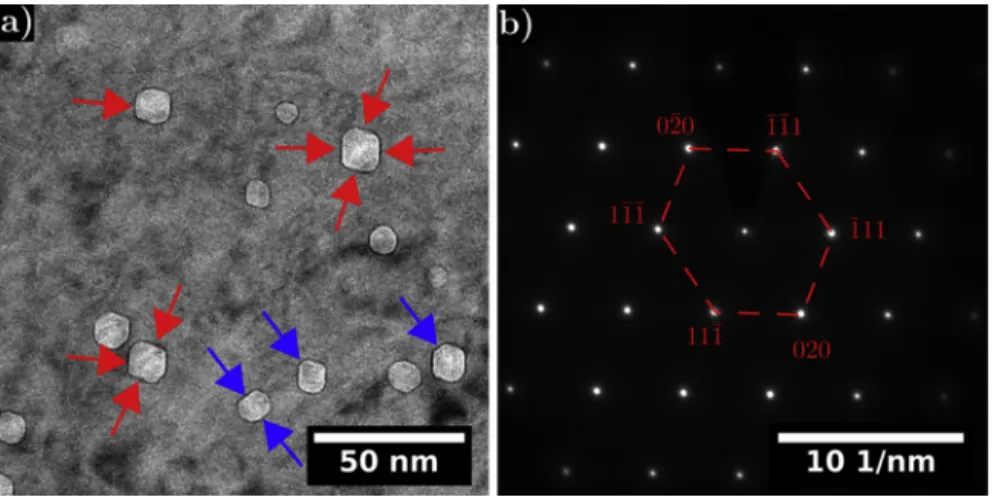
hexagons stretched along one direction. To gain information on the orientation of each facet, the diffraction pattern (Fig. 2b) was compared to the facets of the cavities. Over the six facets, four of them lie in {111} planes (shown by the red arrows) while two lie in {020} planes (shown by the blue arrows) as evidenced inFig. 2a).
3.2. Radiation Induced Segregation on irradiation defects
Radiation Induced Segregation (RIS) around both the cavities and the loops was investigated in TEM. Quantifications were performed on an area 60 ± 10 nm thick.Fig. 3 presents the Cr, Fe, Ni, Si and Mn EDXS mapping of a cavity.Fig. 4 introduces the atomic composition profiles across a cavity and the tip of a Frank loop edge-on. Both the cavity and the Frank loop are segregated. They are nickel and silicon enriched while depleted in chromium, iron and manganese. On both defects the segregation is not homogeneous and the maximum amount of segregation is around ΔCr ≈ − 3–6 at. %, ΔNi ≈ + 8–13 at. % and ΔSi ≈ + 3–5 at. %. InFig. 4, the iron segregation possesses a M-shaped profile indicating that iron is pushed back from the defects. By super-imposing the STEM Bright Field (BF) image and the chemical map, it appears that segregation occurs on the void surfaces (Fig. 3). On the edge-on loop analysed inFig. 4, the segregation is especially marked at the loop tips due to a geometric effect. Indeed, the contribution of segregation at the loops extremities in the foil depth is higher. There-fore, our TEM analysis revealed the presence of irradiation defects (Frank loops and cavities) in the 316 L alloy induced by the proton ir-radiation. Similar intragranular segregation on irradiation defects was already evidenced by Atom Probe Tomography (APT) [27–29] in agreement with our results. To the author knowledge, solely Edwards et al. [26] and Fukuya et al. [30] reported segregation on voids or dislocations using TEM but did not present any imaging of it. For the first time, TEM analyses of the RIS intragranular segregation permitted to link the segregated area to the defect nature. These should be com-bined to APT measurements to provide even more accurate chemical compositions. In addition, these results on a proton pre-irradiated 316 L alloy are similar to those on a decommissioned baffle-to-former bolt [24]. Our results demonstrate proton irradiation is an efficient tool to emulate the neutron induced microstructure and microchemistry. 3.3. Effect of irradiation on the oxide morphology and thickness
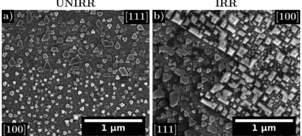
After 24 hours oxidation, SEM images reveal the presence of an outer oxide in the form of small crystallites on both the unirradiated (Fig. 5a) and the irradiated (Fig. 5b) areas of the 316 L sample. The outer layer formed on both regions were compared after oxidation. Bigger and more numerous crystallites are present in the irradiated area inducing a higher outer oxide coverage (75 ± 5 % in the irradiated area vs 58 ± 5 % in the unirradiated one). Their sizes range between
Fig. 1. Frank loops imaged in TEM a) diffraction pattern on [101] zone axis in 2-beam conditions along 1/2 [1-3-1] (red circle: objective aperture used to image the
loops, the scale used in the diffraction pattern is representative of the reciprocal space), b) and c) DF images on the rel-rod streak imaging one loop family edge-on.
were each time obtained to perform the quantifications presented. Frank loops were imaged thanks to the Rel-Rod Dark Field (DF) technique in two-beam conditions. To do so the sample was oriented close to [101] zone axis with g = 1/2 < 131 > . The loops were quantified o n a n a rea b ig e nough t o b e r epresentative a nd w ith a magnification allowing to image small loops. The total loop density was obtained by multiplying by four the measured density of the imaged family as the loop distribution was considered isotropic along {111} crystallographic plane. The quantification of the size and density of the loops was made by performing a loop threshold using the ImageJ software [25]. Cavities or voids were imaged using the under/over focus technique. They appear surrounded by a dark fringe in under-focus condition while surrounded by a bright fringe in over-under-focus condition. Cavities size and density were quantified using the ImageJ software [25]. Efforts were made to estimate the uncertainties at best. Therefore, the lamella thickness and the measured defects number were considered to estimate the densities uncertainties. The standard de-viation and the uncertainty on the measurement itself were taken into consideration to estimate the sizes uncertainties. Thickness measure-ments of the local areas where the defects were imaged were performed by acquiring an unfiltered image and a zero-loss image from the same area under identical conditions.
3. Results and discussion
3.1. Characterization of irradiation defects
The microstructure induced by the proton irradiation in the studied 316 L consisted of dislocation loops and cavities. Fig. 1a) shows the diffraction pattern on the 316 L matrix. It was obtained by tilting away from [101] zone axis along g = 1/2 [1–3] in order to be in two-waves condition. Circled in red in the image is a white streak also called Rel-Rod induced by the presence of Frank loops. By selecting this streak with the objective diaphragm, the Frank loops edge-on are imaged as presented in the Dark Field (DF) images of Fig. 1b) and c). The loops have sizes ranging from 3 nm to 92 nm with an average size of 21 ± 14. The total loop density is of 2 ± 1 x 10²² m−3. These values are consistent with other results both on proton and neutron irradiated austenitic stainless steels [13,14,24,26].
Fig. 2a) show the cavity distribution under-focus on the 316 L alloy proton irradiated. Their sizes range from 1 nm to 20 nm with an average size of 11 ± 2 nm and a density close to 5 ± 2 x 10²¹ m−3. Once again, these results are consistent with others both on proton and neutron irradiated austenitic stainless steels [13,14,24,26]. It confirms that proton irradiation is an efficient tool to simulate the neutron mi-crostructure (Frank loops and cavities). When the cavities reach a suf-ficient size they appear faceted with facets all parallel from one faceted void to the other. These faceted cavities can be described as regular
10 and 120 nm. Fukuya et al. [9] and Deng et al. [18] observed a higher number and a bigger size of crystallites as the irradiation dose increase in accordance with our results. Differences in the open literature re-garding the outer oxide might originate from the different oxidation durations. In our case we investigated a short oxidation time whereas most studies focus on longer oxidation durations and thus cannot an-ticipate the effect of irradiation on the oxidation nucleation and growth during the oxidation first stages. In addition, after 24 hours oxidation, specific shapes are observed depending upon the crystallographic or-ientation of the underlying metal grain in both the irradiated and unirradiated regions as seen inFig. 5a) and b). This is consistent with Soulas’ results [5]. On [100] grain orientation squared based pyramids are observed whereas flat triangles are seen on top of [111] grain or-ientation (Fig. 5). No differences in the crystallites shapes were noticed
between the irradiated and unirradiated area on a same grain orienta-tion.
TEM cross-section imaging of the oxide formed in both the irra-diated and unirrairra-diated region highlighted the presence of a duplex oxide (Fig. 6). The duplex character of the oxide is not affected by ir-radiation as expected from the literature [9,17–19]. The outer crystal-lites are formed on top of the inner oxide layer. As previously observed on the SEM images, the outer crystallites are bigger on the irradiated area than on the unirradiated one. Nevertheless, the inner oxide layer is thicker on the irradiated area compared to that formed on the uni-rradiated one (53 ± 6 nm vs 10 ± 2 nm). Fig. 7shows TEM bright field images over-focus of the oxide layers formed in the a) and b) unirradiated and c) and d) irradiated area. Since the same sample preparation was used, the brighter regions in the inner oxide layer Fig. 2. a) TEM BF under-focus imaging of the cavities distribution (facets lying in {111} planes are shown by the red arrows, facets lying in {020} planes showed by
the blue arrows) and b) associated diffraction pattern in [101] zone axis (the scale used in the diffraction patterns is representative of the reciprocal space).
Fig. 3. HAADF image and associated EDXS mapping of Cr, Fe, Ni, Si and Mn on the cavity framed in red.
formed on the irradiated area are not due to a thickness difference coming from the foil preparation but are thought to be porosities formed during the oxidation process. The inner oxide layer is dense and continuous in the unirradiated area whereas it is porous in the irra-diated area. Further STEM High Angle Annular Dark Field (HAADF) images at grain boundaries were realised to look upon the oxide pe-netration at the grain boundaries as shown inFig. 8a) and b) in the unirradiated and irradiated regions respectively. These evidence that the intergranular oxide penetration is deeper in the irradiated area (141 ± 2 nm) than in the unirradiated area (42 ± 2 nm). The pre-sence of cavities induced by the proton irradiation at the metal/oxide interface is evidenced inFigs. 6b) and9a). Similarly,Fig. 9b) and c) reveal the presence of Frank loops at the metal/oxide interface. No preferential oxidation around these defects is observed suggesting that they do not affect the oxidation front.
3.4. Effect of irradiation on the oxide structure
Even if in previous works irradiation was not found to modify the oxide structure, this assumption was verified and the oxide scales formed were looked upon using High Resolution TEM (HRTEM). This HRTEM analysis and associated Fast Fourier Transforms (FFTs) are introduced inFigs. 10 and 11for the unirradiated and irradiation area respectively. InFig. 10a), a HRTEM image of the metal, inner oxide and outer oxide is introduced. FFTs of the metal, inner oxide and outer oxide are presented inFig. 10b)–d) which are the red, green and blue
framed areas respectively. For the irradiated area, since the oxide is thicker, both oxides and the matrix could not be imaged at the same time on one HRTEM image. The overall oxide is depicted inFig. 11a) and the HRTEM image introduced inFig. 11b) focus on the metal/oxide interface. In the green framed area is presented a FFT of the inner oxide layer. The Inverse FFT (IFFT) of the area framed in red inFig. 11b) is shown inFig. 11c). In both the unirradiated and irradiated regions, the inner and outer oxides are indexed as spinel phase AB2O4(space group Fd-3 m). This is consistent with previous finding and, as expected from the literature, irradiation do not affect the crystallographic structure of the oxide layers [9,19].
In the FFTs obtained on the inner oxide layer (green frames of
Figs. 10c) and11b), no rings suggesting the presence of nanocrystals with an “isotropic” crystallographic orientation distribution can be observed. Indeed, isolated spots are present on the FFTs at specific diffraction angles indicating the presence of an oriented oxide. In
Fig. 10e) the FFTs of the inner oxide and the metal are superimposed. The spinel inner oxides are indexed in the same zone axis as the sub-strate (Fig. 10e). This reveals that a cube/cube epitaxial orientation relationship exists and is established between the inner oxide and the underlying metal grain. The presence of such relationship between the inner layer and the substrate was already mentioned by Soulas on an unirradiated 316 L [5]. Our results show that irradiation do not modify the epitaxial orientation relationships established between the oxide layers and the substrate. Nevertheless, as it can be seen inFig. 11c), the inner oxide layer is heavily strained. The inner oxide region circled in Fig. 5. SEM SE images (5 kV) on a [100]/[111] grain boundary on a) the unirradiated area and b) the irradiated area.
Fig. 6. STEM HAADF images of the oxide formed on a
same grain orientation a) on the unirradiated area and b) on the irradiated area (some outer oxide crystallites are shown by the blue arrows, the inner oxide layers are shown by the red arrows).
Fig. 7. TEM BF images over-focused of the oxide formed on a same grain orientation a) and b) on the unirradiated area, c) and d) on the irradiated area (the cavities
cyan is not well oriented (off-axis) whereas the region of the inner oxide circled in magenta is well oriented and on-axis. Numerous defects (point defects, dislocations, etc) are believed to be present and would distort the lattice. The presence of a defective monocrystal is in dis-agreement with the finding of several authors who reported the for-mation of a polycrystalline oxide [6,9,10].
Regarding the outer crystallites, the faceted ones are in the same zone axis as the inner layer (respectively blue and green frames in
Fig. 10d) and c). InFig. 10f), the FFTs of the inner oxide and outer oxide are superimposed. It reveals that the crystallites grew on the inner oxide layer sharing an epitaxial twin-like relationship with a (-1-11) twin plane. Since the same crystallites morphologies were observed on both the irradiated and unirradiated areas (Fig. 5), it is likely that
crystallites in the irradiated region also grew onto the inner oxide layer sharing the same epitaxial twin-like relationship.
3.5. Effect of irradiation on the chemistry of the oxides
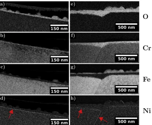
In this work, to assess the effect of irradiation on the oxides chemistry, we firstly used EFTEM imaging to visualise enrichment in a given element.Fig. 12shows the EFTEM mapping of the oxide on both the irradiated and unirradiated regions for the oxygen, iron, chromium and nickel. On each map, the regions rich in the map element appear light. The oxide formed after the 24 hours oxidation is visible on the oxygen maps in Fig. 12a) and e). The iron and chromium maps (Fig. 12b), c), f) and g) evidence that the outer crystallites are iron-rich Fig. 8. STEM HAADF images of the oxide penetration at the grain boundary a) in the unirradiated area and b) in the irradiated area.
Fig. 9. TEM a) BF image over-focus of the oxide formed on a same grain orientation on the unirradiated area and on the irradiated area respectively with the cavities
shown by the red arrows and associated zooms, b) BF image of a Frank loop in the irradiated area and c) associated DF image of the Frank loop (2-beam conditions close to [101] zone axis).
Fig. 10. a) HRTEM image of the metal/inner oxide interface in the unirradiated area in [101] zone axis, b) FFT of the red framed matrix area, c) FFT of the green
framed inner oxide area, d) FFT of the blue framed outer oxide area, e) superimposition of the diffraction spots of the inner oxide and the matrix from the FFTs and f) superimposition of the diffraction spots of the inner and outer oxides from the FFTs.
whereas the inner oxide layer is chromium rich. A slight nickel en-richment is also seen at the metal/oxide interface as evidenced by red arrows inFig. 12d) and h). No distinct change can be observed in the qualitative chemistry of the oxide scales between the irradiated and unirradiated area. This is consistent with previous finding [5,6,9,17,19].
Further EDXS, EELS analyses allowed to quantify the enrichments seen in EFTEM mapping. Both EELS and EDXS analyses were performed on the oxides formed in the unirradiated and proton pre-irradiated areas.Fig. 13reveals the composition profile across both the outer and inner oxides a) in the unirradiated and b) the irradiated areas.Fig. 13a) confirm that the outer oxide is magnetite (Fe3O4) and that the inner oxide is a mixed iron/chromium spinel oxide. Since the outer/inner oxide interface is not perfectly planar, between 10 and 15 nm in
Fig. 13a), the chromium content progressively increase while the iron content decease before reaching stability. In addition, this EELS line-scan reveals that a small amount of nickel is included into the inner oxide layer. The inner oxide layer can thus be describe as (FeCrNi)3O4.
At the metal/oxide interface (∼26 nm), a clear nickel enrichment coupled with a slight chromium depletion is noticed as already ob-served in the EFTEM map (Fig. 12d). All these observations are in agreement with other TEM analyses of the oxide scales on unirradiated materials [5,6,9,17,19].
The EELS linescan in the irradiated region presented inFig. 13b) reveals a duplex behaviour of the inner oxide layer and the presence of an outer oxide iron rich and containing a small amount of nickel. At ∼ 122 nm, as on the unirradiated area, a peak of nickel is visible and highlight a thin nickel enrichment at the metal/oxide interface. Close to 97 nm onFig. 13b), the chromium/iron ratio is reversed but the nickel content remain constant between the two regions. Toward the medium/ outer oxide the oxide layer is chromium rich while toward the metal the inner oxide is iron-rich. Such duplex inner oxide was only seen on the irradiated area. Since the area close to the metal/oxide interface is poorer in chromium it is less protective than the outer part. These two part of the inner oxide will possess different properties with respect to the anionic transport within the oxide. On the irradiated area, the inner Fig. 11. a) TEM BF image of the oxide formed in the irradiated area b) HRTEM image of the metal/inner oxide interface framed in yellow in a) in [111] zone axis and
associated FFT in the green framed area with the bandpass mask diameter drawn in blue c) IFFT of the area framed in red in a) with a well oriented region circled in magenta and a strained one circled in cyan.
Fig. 12. EFTEM mapping of oxygen, chromium, iron and nickel in the a), b), c), d) unirradiated area and e), f), g), h) irradiated area respectively, red arrows
oxide was mainly a chromium rich oxide and only small areas exhibited this duplex behaviour.
The results from the quantitative analyses on the inner oxide in the unirradiated area and on the one formed in the irradiated area in the chromium rich region are introduced inTable 2. In this table the results are presented both for the EELS and EDXS analyses. As previously mentioned, the quantification presented in Table 2 were obtained without oxygen. The chromium over chromium/nickel/iron ratios were calculated and the inner spinel oxides are described as AB2O4with A divalent metal cations and B trivalent ones. Overall, from EELS and EDXS analyses, the inner oxide can be written accordingly to (NixFe1-x) (CryFe1-y)2O4 with 0.6 ≥ x ≥ 0.3 and 0.9 ≥ y ≥ 0.65. Nickel was al-ways better detected in the EDXS analyses. It relates to EELS sensitivity being lower at higher energy losses while Ni K-line is well detected and quantified in EDXS analysis. A higher amount of chromium is detected in the inner oxide layer formed on the irradiated area (Cr/ (Cr + Fe + Ni)unirr≈0.50 vs Cr/(Cr + Fe + Ni)irr≈0.56). The forma-tion of oxide richer in chromium onto irradiated materials was already reported by several authors [16,17,19].
Using the crystal field theory, we can predict the spinel type (normal or inverse) of the oxides as the stabilization energy of the different spinels can be calculated [31]. The AB2O4 spinel type is defined ac-cording to the distribution of the A and B cations in the cell. In a normal spinel, the B cations are on octahedral sites and the A cations on tet-rahedral sites, whereas in an inverse spinel the A cations are in octa-hedral sites and the B cations half in tetraocta-hedral sites and half in oc-tahedral sites. Normal spinels can be written [A2+](B3+)
2O4 and
inverse spinels [B3+](B3+A2+)O
4 where square brackets represent tetrahedral sites and parentheses octahedral sites.
For an isolated atom, the energy level of the five 3d atomic orbitals are degenerated and possess the same energy. However, cations in oc-tahedric or tetrahedric environments will be subjected to an electro-static field due to the presence of 6 or 4 ligands respectively. It will cause a splitting Δ of the d-orbitals in two sets with different energies. For the octahedral configuration, three orbitals are stabilised and at a lower energy than the other two. The lower orbitals are referred to as t2gand the higher ones as eg. The tetrahedral configuration also pos-sesses two sets of district orbitals, e (lower energy) and t2(higher en-ergy). The crystal field splitting energy are referred as to Δoand Δtfor octahedral and tetrahedral symmetry respectively.
Ni2+, Fe2+, Fe3+ and Cr3+ are all transition metals with [Ar] 4s03d8, [Ar]4s03d6, [Ar]4s03d5and [Ar]4s03d3electron configuration respectively. For the iron ions, Fe3+ is a high spin system with no Crystal Field Stabilization Energy (CFSE) while Fe2+has a higher CFSE (CFSE = -0.4 Δo). This explain the inverse spinel configuration of Fe3O4 ([Fe3+](Fe2+Fe3+)O
4) since the divalent ion has more gain in octa-hedral geometry than the trivalent ion. Looking upon a FeCr2O4spinel oxide, Cr3+ is a high-spin ion with a higher CFSE than the divalent high-spin Fe2+ion (CSFE
Cr3+= -1.2 Δo> CFSEFe2+). Therefore, Cr3+ occupy the octahedral sites resulting in a normal spinel configuration ([Fe2+](Cr3+)
2O4) as opposed to a NiFe2O4oxide. Indeed, CFSENi2+= -1.2 Δoand Ni2+will be in the octahedral sites and Fe3+in tetrahedral sites ([Fe3+](Ni2+Fe3+)
2O4). In our case, for a mixed iron/nickel/ chromium spinel, Ni2+ and Cr3+ cations, having higher CFSE than Fig. 13. EELS quantitative profiles on the oxide formed on a same grain orientation a) in the unirradiated area and b) in the irradiated area.
Table 2
EDXS and EELS quantitative analyses of the inner oxides formed on the unirradiated and irradiated areas on a same grain orientation.
Analysed area Method Cr
(at. %) Fe (at. %) Ni (at. %) Cr/(Cr + Fe + Ni) AB2O4(A: M
2+, B: M3+)
Unirradiated EELS 50 36 14 0.50 (Ni0.4Fe0.6)(Cr1.5Fe0.5)O4
EDXS 44 37 19 0.44 (Ni0.6Fe0.4)(Cr1.3Fe0.7)O4
Irradiated EELS 56 27 17 0.56 (Ni0.4Fe0.6)(Cr1.7Fe0.3)O4
EDXS 49 33 18 0.49 (Ni0.5Fe0.5)(Cr1.5Fe0.5)O4
Table 3
EDXS and EELS quantitative analyses of the inner oxides formed on the unirradiated and irradiated areas on a same grain orientation and associated description of the oxides using the crystal field theory.
Analysed area Method AB2O4 [A](B)2O4(square brackets represent tetrahedral sites and parentheses octahedral sites)
Unirradiated EELS (Ni0.4Fe0.6)(Cr1.5Fe0.5)O4 [Fe0.52+Fe3+0.5](Ni2+0.4Cr3+1.5Fe2+0.1)O4
EDXS (Ni0.6Fe0.4)(Cr1.3Fe0.7)O4 [Fe2+0.3Fe3+0.7](Ni2+0.6Cr3+1.3Fe2+0.1)O4
Irradiated EELS (Ni0.4Fe0.6)(Cr1.7Fe0.3)O4 [Fe0.62+Fe3+0.3Ni2+0.1](Ni2+0.3Cr3+1.7)O4
Fe2+and Fe3+ions, they will occupy in priority octahedral sites while the iron cations can occupy both tetrahedral and octahedral sites.
Table 3present the description of the spinel inner oxides in the uni-rradiated and iuni-rradiated areas using the results from the EELS and EDXS analyses and the crystal field theory. This analysis could not be sub-stantiated by experimental results on the metal valence state but still provides a valuable chemical description of the oxides. Nonetheless, one should remember that metal valence state will in addition be af-fected by strain and irradiation.
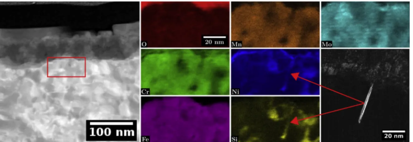
To better understand where from such differences in the oxide composition might arise, chemical mapping was performed at the metal/oxide interface to investigate the role of irradiation defects.
Fig. 14shows the TEM EDXS analysis made at the metal/oxide interface of O, Cr, Fe, Mn, Ni, Si, Mo. This specific region was chosen to obtain chemical maps of irradiation defects at the metal/oxide interface since a Frank loop is lying edge-on at the oxidation front as shown in the DF image of the loop. This figure highlights that irradiation defects remain segregated near the oxidation front. The Frank loop is still enriched in nickel and silicon and depleted in chromium and iron. However, silicon appear to be depleted from the Frank loop tip located at the oxide front. Silicon probably left the loop tip and is diluted into the surrounding substrate or into the medium as none can be found in the inner oxide layer. No oxygen penetration can be observed toward the loop in-dicating that no preferential oxidation of the irradiation defects seems to occur at the oxide front. Apart from the silicon, segregation around irradiation defects is not destabilised by the oxidation front and the oxidation process.
EDXS mapping of the grain boundary oxidation in the irradiated area is introduced inFig. 15with the O, Cr, Fe, Ni, S, Mn, P, Si and Mo maps. As expected the grain boundary is segregated due to RIS. It is chromium, iron, manganese and molybdenum depleted and nickel, phosphorus and silicon enriched (Fig. 15). By investigating the tip of the intergranular oxidation/RIS, it appears that the silicon and
phosphorus contents progressively decrease going from the inter-granular RIS toward the oxidation front over 10 nm whereas the Ni tends to accumulate at the tip of the oxide penetration without being included into the oxide. The nickel content reaches ∼ 50 at. % in the oxide penetration tip near region. These observations suggest that si-licon and phosphorus are preferentially dissolved into the medium. This behaviour is alike to the one observed for the loop lying at the metal/ oxide interface as silicon was also found to be sucked probably into the medium (Fig. 14).
The sulphur map ofFig. 15evidences a sulphur enrichment at the metal/oxide interface. To confirm its presence, inFig. 16, two EDXS spectra were extracted, one from the matrix and the other on the be-lieved S-enriched area. As the Kα line of sulphur is really close to the molybdenum Lα line, the spectra were normalised on the Mo-Kα line and attention was paid on the relative intensity of the overall S-Kα and Mo-Kα lines. Since there is a clear increase of intensity of the S-Kα line compared to the Mo-Lα line, it indicates that sulphur is indeed genu-inely detected and present at the metal/oxide interface. Tice et al. [32] and West et al. [33] also evidenced sulphur at the metal/oxide. Even if the lamella was extracted away from any visible inclusion, it is believed that such sulphur comes from the dissolution of a nearby MnS inclusion commonly observed in commercial 316 L.
4. Discussion
The experimental results presented above allowed to study the ef-fects of irradiation and especially the effect of irradiation deef-fects such as Frank loops and cavities and those of RIS on the oxides morphology, structure and chemistry.
4.1. Effect of irradiation on the surface oxide structure
Irradiation do not modify the duplex character of the oxide nor the Fig. 14. STEM HAADF image and associated EDXS quantitative maps of O, Cr, Fe, Mn, Ni, Si and Mo near the metal/oxide interface and the DF image associated with
the Frank loop detected.
oxides spinel structure (Figs. 10 and 11). In both regions, the outer crystallites possess favoured crystallites morphologies contingent on the underlying metal grain orientation (Fig. 5) and are made of magnetite (Fe3O4). This hints towards the existence of a crystallographic or-ientation relationship between the substrate and the oxide scales. It also suggests that irradiation do not affect the establishment of the epitaxial relationship. The HRTEM analysis revealed that the chromium rich inner oxide layers are heavily strained oxides sharing a cube/cube epitaxial orientation relationship with the underlying metal grain. Therefore, the presence of irradiation defects near the metal/oxide in-terface as seen inFig. 9do not disturb the establishment of the epitaxial relationship nor the oxide epitaxial growth.
4.2. Effect of irradiation on the surface oxide morphology
The initial microstructure of the irradiated 316 L was found to play a key role in the germination and growth of the outer oxide since changes in size and density of crystallites were observed (Fig. 5). Irra-diation defects enhance the outer oxide nucleation and act as pre-ferential nucleation sites for the crystallite nucleation during the oxi-dation first steps inducing the observed higher number of crystallites. Since the outer oxide layer is formed by cationic diffusion within the inner oxide layer and by a dissolution/reprecipitation process [1,8], the bigger size of outer crystallites in the irradiated area reveals that dif-fusion of cation through the inner oxide layer is faster.
In this work we also observed that the oxide formed on top of the irradiated area is thicker and porous as seen inFig. 7. It is likely that the porosities arise from imbalanced flux of cationic and anionic species due to irradiation. These porosities provide interconnections between the media and the inner oxide layer/substrate. They act as preferential diffusion paths and are responsible for the faster diffusion of oxygen and metallic cation and therefore the enhanced growth of the outer and inner oxide layers in the irradiated area. This porous oxide is less protective than the one formed on the unirradiated area. The ob-servation of thicker oxides on irradiated material as evidenced inFig. 6
reveals that irradiation promotes the oxidation kinetic. The oxidation kinetic is up to 5 time faster on the irradiated area after 24 hours oxi-dation. Among the authors having studied the effect of irradiation for longer oxidation duration, Gupta [34] and Deng [18] also highlighted that irradiation enhances the oxidation kinetic. Both of them reported
oxidation kinetics between almost 2 and 4 time faster on the irradiated samples for oxidation during 360 and 500 hours respectively which is coherent with our results. Nonetheless, as the oxidation duration in-creases and once the oxide is established the oxidation kinetic is be-lieved to slow down. This would explain the slightly lower oxidation kinetic obtain at longer oxidation time. Since inner oxides are thicker on irradiated areas, it indicates that oxygen diffusion through the inner oxide layer is faster on irradiated regions. This enhanced diffusion should result from the high concentration of defects (point defects, dislocations, porosities, etc.) in the oxide scale [8]. However this is contrary to the findings of Perrin et al. who used tracer experiments and observed that oxygen diffusion was slower in the inner oxide layer [19]. This might results from the sample preparation. Indeed, samples in which cold-work is induced by the polishing have faster oxidation ki-netics as revealed by Warzee et al. and Ziemniak et al. [35,36]. How-ever, when irradiated this cold-work will disappear since, as shown by Pokor et al. [37], the initial network of dislocations tends to disappear under irradiation. Therefore, for a sample in which the polishing brought cold-work, the irradiated area will be cold-work free and oxygen diffusion will be slower resulting is thinner oxides. This would explain the slower oxygen diffusion in the irradiated area observed by Perrin et al. [19]. Nevertheless, this assumption has to be confirmed with more observations and tracers experiments. In addition, sample polishing have to be controlled and validation of the results obtained in this work using mechanically polished proton (or neutron) irradiated samples is needed to see if the induced cold-work overcome the influ-ence of irradiation.
4.3. Effect of irradiation on the surface oxide chemistry
Irradiation defects such as Frank loops and cavities are present at the metal/oxide interface and are not preferentially oxidised as pre-viously seen inFigs. 9 and 14. Nonetheless, they are thought to promote the metallic cation diffusion toward the metal/oxide interface. This results in the formation of the observed inner oxides richer in chromium (Fig. 13). Such behaviour was already reported by several authors [16,17,19]. The literature attest that oxygen diffusion through the inner layer is slower for Cr-rich oxides [7]. Nonetheless, the presence of porosities in the inner oxide layer acting as diffusion short-cuts is the primarily process responsible for the enhanced growth of the inner Fig. 16. EDXS spectra extracted from the areas framed in red in the previous quantitative mapping of the grain boundary oxidation, red and blue framed areas in the
penetration morphology, depth etc, several grain boundaries of dif-ferent natures should further be investigated.
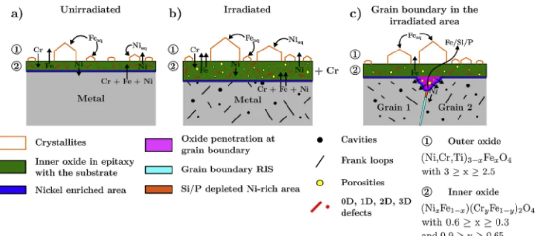
4.5. Synthesis: oxidation mechanism of unirradiated and irradiated 316L exposed to PWR environment during short time
By combining the morphological, structural and structural results,
Fig. 17explains the effect of irradiation on the stainless steel oxidation.
Fig. 17a) depicts the oxidation occurring in the unirradiated area. In this regions, a duplex oxide is formed and composed of faceted outer crystallites and an inner oxide in epitaxy with the substrate. This inner oxide is formed by an anionic diffusion mechanism and grows toward the metal whereas the outer oxide layer is formed by cationic diffusion within the inner oxide layer and by a dissolution/reprecipitation pro-cess [1,8,19]. The inner oxide layer is a mixed iron/chromium/nickel spinel oxide which contains defects and is strained. The outer crystal-lites are made of magnetite. At the metal oxide/interface a thin nickel enrichment is present and arise from the nickel rejection from the inner oxide. When irradiation defects are presents as shown inFig. 17b), the metallic ions diffusion is enhanced by their presence and the inner oxide layer is richer in chromium. In the oxidation first stages these defects act as preferential nucleation sites for the outer crystallites in-ducing a higher number of crystallites. These will grow faster as will the inner oxide layer due to the presence of porosities in the inner oxide enhancing cation and anion diffusions through the inner layer. There-fore, on irradiated materials, the inner oxide layer will be thicker and porous. As for oxidation at grain boundaries (Fig. 17c), the RIS occur-ring in irradiated materials promotes the oxidation at grain boundaries and induces deeper oxide penetration. RIS was also found affected by the oxidation front and below the oxide penetration the silicon and phosphorus content gradually increase before reaching their RIS con-tent while nickel accumulates in this region due to its rejection from the oxide.
5. Conclusion
A solution annealed 316 L sample was irradiated using 1.5 MeV protons at 380 °C to 1.5 dpa. This study presents the comparison of the oxide formed both in the irradiated and unirradiated region of the sample oxidised in nominal PWR environment.
The following conclusions can be drawn:
- Proton irradiation is an efficient tool to simulate the neutron in-duced microstructure.
- Irradiation does not affect the duplex character of the oxide nor modify the spinel structure of the oxide and the cube/cube epitaxial orientation relationship established between the oxide scales and the substrate.
Fig. 17. Schematic of the oxidation mechanism of unirradiated and irradiated 316 L austenitic stainless steel exposed to PWR medium during short time oxidations. oxide layer in the irradiated area and not the chromium content.
Cau-tion must be exercised and the protectiveness of the inner oxide layer cannot be only related to the inner layer chromium content. In our work, the fast diffusing paths induced by the porosities overstep the slower oxygen diffusion in Cr-rich oxides.
On the irradiated region a duplex character of the inner oxide layer was highlighted in Fig. 13b). Such behaviour was not observed on the whole oxide scale but only in some scarce areas. In these regions, the outer part of the inner oxide layer is chromium-rich while the inner part is iron-rich. Such inner region will be less protective as it is less mium-rich. A higher density of segregated defects (depleted in chro-mium) initially present in the observed iron-rich areas could be re-sponsible for this oxidation behaviour. Indeed, the substrate below the oxidation front will thereby be locally depleted in chromium and thus an iron-rich oxide will be formed.
4.4. Effect of irradiation on the grain boundary oxidation
The grain boundaries act as diffusion s hort-cuts a nd a re pre-ferentially oxidised. While intergranular corrosion occurs at the grain boundary in both the unirradiated and irradiated region, the deeper oxide penetration in the irradiated area indicates a promoted inter-granular corrosion by irradiation. RIS is likely to be responsible for this preferential oxidation. The low chromium content at grain boundaries induced by RIS (Fig. 15) would increase the grain boundary sensitivity, resulting in higher corrosion susceptibility. Terachi et al. [27] pre-viously reported that the oxidation kinetic is linked to the alloy chro-mium content. The less chrochro-mium in the alloy, the more oxidation is promoted. Even if surface and grain boundary oxidations differ, it is likely that a preferential oxidation would occur at grain boundaries depleted in chromium by the RIS. Nevertheless, this is dependent on the nature of the grain boundary. Grain boundary type and nature are re-lated to the RIS occurring and therefore so is their oxidation behaviour [38,39].
The segregation induced by irradiation was found affected by the oxidation front (Fig. 15). Silicon and phosphorus contents gradually decreased toward the oxide penetration. This suggests that both are sucked from the grain boundary and potentially dissolved into the medium. Such behaviour was already observed on the loop lying at the metal/oxide interface. Nickel, is however preferentially segregated at the oxide tip and accumulate ahead of the oxide front. It is rejected from the oxide toward the metal during its formation and growth. In-deed, iron and chromium possess a higher affinity to oxygen than nickel thus the rate of incorporation of the latter in the oxide is the smallest.
In a nutshell, random grain boundaries in irradiated area will be sensitised by RIS and the chemical composition changes at grain boundaries induced by RIS affect t he o xidation a nd o verall S CC re-sistance. Since grain boundary nature can play a role on the oxide
References
[1] D.H. Lister, R.D. Davidson, E. McAlpine, The mechanism and kinetics of corrosion product release from stainless steel in lithiated high temperature water, Corros. Sci. 27 (1987) 113–140,https://doi.org/10.1016/0010-938X(87)90068-0.
[2] M. Da Cunha Belo, M. Walls, N.E. Hakiki, J. Corset, E. Picquenard, G. Sagon, D. Noel, Composition, structure and properties of the oxide films formed on the stainless steel 316L in a primary type PWR environment, Corros. Sci. 40 (1998) 447–463,https://doi.org/10.1016/S0010-938X(97)00158-3.
[3] B. Stellwag, The mechanism of oxide film formation on austenitic stainless steels in high temperature water, Corros. Sci. 40 (1998) 337–370,https://doi.org/10.1016/ S0010-938X(97)00140-6.
[4] R.L. Tapping, R.D. Davidson, E. McAlpine, D.H. Lister, The composition and mor-phology of oxide films formed on type 304 stainless steel in lithiated high tem-perature water, Corros. Sci. 26 (1986) 563–576, https://doi.org/10.1016/0010-938X(86)90024-7.
[5] R. Soulas, M. Cheynet, E.F. Rauch, T. Neisius, L. Legras, C. Domain, Y. Bréchet, TEM investigations of the oxide layers formed on a 316L alloy in simulated PWR en-vironment, J. Mater. Sci. 48 (2013) 2861–2871, https://doi.org/10.1007/s10853-012-6975-0.
[6] T. Terachi, K. Fujii, K. Arioka, Microstructural characterization of SCC crack tip and oxide film for SUS 316 stainless steel in simulated PWR primary water at 320 °C, J. Nucl. Sci. Technol. 42 (2005) 225–232,https://doi.org/10.3327/jnst.42.225. [7] T. Terachi, T. Yamada, T. Miyamoto, K. Arioka, K. Fukuya, Corrosion behavior of
stainless steels in simulated PWR Primary Water effect of chromium content in alloys and dissolved hydrogen, J. Nucl. Sci. Technol. 45 (2008) 975–984,https:// doi.org/10.1080/18811248.2008.9711883.
[8] D.D. Macdonald, The history of the point defect model for the passive state: a brief review of film growth aspects, Electrochimica Acta 56 (2011) 1761–1772,https:// doi.org/10.1016/j.electacta.2010.11.005.
[9] K. Fukuya, H. Nishioka, K. Fujii, Y. Kitsunai, Characterization of surface oxides formed on irradiated stainless steels in simulated PWR primary water, Proc. of the International Symposium Fontevraud VIII (2014),https://inis.iaea.org/search/ search.aspx?orig_q=RN:46081624.
[10] Y.Z. Huang, J.M. Titchmarsh, TEM investigation of intergranular stress corrosion cracking for 316 stainless steel in PWR environment, Acta Mater. 54 (2006) 635–641,https://doi.org/10.1016/j.actamat.2005.10.011.
[11] S.M. Bruemmer, E.P. Simonen, P.M. Scott, P.L. Andresen, G.S. Was, J.L. Nelson, Radiation-induced material changes and susceptibility to intergranular failure of light-water-reactor core internals, J. Nucl. Mater. 274 (1999) 299–314,https://doi. org/10.1016/S0022-3115(99)00075-6.
[12] S.J. Zinkle, P.J. Maziasz, R.E. Stoller, Dose dependence of the microstructural evolution in neutron-irradiated austenitic stainless steel, J. Nucl. Mater. 206 (1993) 266–286,https://doi.org/10.1016/0022-3115(93)90128-L.
[13] D.J. Edwards, E.P. Simonen, S.M. Bruemmer, Evolution of fine-scale defects in stainless steels neutron-irradiated at 275 °C, J. Nucl. Mater. 317 (2003) 13–31,
https://doi.org/10.1016/S0022-3115(03)00002-3.
[14] K.J. Stephenson, G.S. Was, Comparison of the microstructure, deformation and crack initiation behavior of austenitic stainless steel irradiated in-reactor or with protons, J. Nucl. Mater. 456 (2015) 85–98,https://doi.org/10.1016/j.jnucmat. 2014.08.021.
[15] G.S. Was, J.T. Busby, T. Allen, E.A. Kenik, A. Jensson, S.M. Bruemmer, J. Gan, A.D. Edwards, P.M. Scott, P.L. Andreson, Emulation of neutron irradiation effects with protons: validation of principle », J. Nucl. Mater. 300 (2002) 198–216,https:// doi.org/10.1016/S0022-3115(01)00751-6.
[16] J. Gupta, J. Hure, B. Tanguy, L. Laffont, M.C. Lafont, E. Andrieu, Characterization of ion irradiation effects on the microstructure, hardness, deformation and crack in-itiation behavior of austenitic stainless steel: heavy ions vs protons, J. Nucl. Mat. 501 (2018) 45–58,https://doi.org/10.1016/j.jnucmat.2018.01.013.
[17] M. Dumerval, S. Perrin, L. Marchetti, M. Sennour, F. Jomard, S. Vaubaillon, Y. Wouters, Effect of implantation defects on the corrosion of 316L stainless steels in primary medium of pressurized water reactors, Corros. Sci. 107 (2016) 1–8,
https://doi.org/10.1016/j.corsci.2016.02.007.
[18] P. Deng, Q. Peng, E.-H. Han, W. Ke, C. Sun, Z. Jiao, Effect of irradiation on corrosion of 304 nuclear grade stainless steel in simulated PWR primary water, Corros. Sci. 127 (2017) 91–100,https://doi.org/10.1016/j.corsci.2017.08.010.
[19] S. Perrin, L. Marchetti, C. Duhamel, M. Sennour, F. Jomard, Influence of irradiation on the oxide film formed on 316L stainless steel in PWR Primary Water, Oxid. Met. 80 (2013) 623–633,https://doi.org/10.1007/s11085-013-9401-3.
[20] J.F. Ziegler, M.D. Ziegler, J.P. Biersack, SRIM — The Stopping and Range of Ions in Matter, Nucl. Instrum. Methods Phys. Res. Sect. B Beam Interact. Mater. At. 268 (2010) 1818–1823,https://doi.org/10.1016/j.nimb.2010.02.091.
[21] R.E. Stoller, M.B. Toloczko, G.S. Was, A.G. Certain, S. Dwaraknath, F.A. Garner, On the use of SRIM for computing radiation damage exposure, Nucl. Instrum. Methods Phys. Res. Sect. B Beam Interact. Mater. At. 310 (2013) 75–80,https://doi.org/10. 1016/j.nimb.2013.05.008.
[22] R.P. Matthews, R.D. Knusten, J.E. Westraadt, T. Couvant, Intergranular oxidation of 316L stainless steel in the PWR primary water environment, Corros. Sci. 125 (2017) 175–183,https://doi.org/10.1016/j.corsci.2017.06.023.
[23] L. Legras, M.L. Lescoat, S. Jublot-Leclerc, A. Gentils, Optimisation of TEM pre-paration in metallic materials using low voltage ions, Proc. of the European Microscopy Congress (2016),https://doi.org/10.1002/9783527808465.EMC2016. 5973.
[24] M. Boisson, L. Legras, E. Fargeas, P. Cuvillier, R. Mercier, S. Miloudi, J. Tarabay, M. Roch, TEM investigations of the microstructure and oxides at the tip of inter-granular cracks of a baffle former bolt irradiated up to 10 dpa, Proc. of the International Symposium Fontevraud IX, Avignon, France, 2018.
[25] C.A. Schneider, W.S. Rasband, K.W. Eliceiri, NIH Image to ImageJ: 25 years of image analysis », Nat. Methods 9 (2012) 671,https://doi.org/10.1038/nmeth. 2089.
[26] D.J. Edwards, E.P. Simonen, F.A. Garner, L.R. Greenwood, B.M. Oliver, S.M. Bruemmer, Influence of irradiation temperature and dose gradients on the microstructural evolution in neutron-irradiated 316SS, J. Nucl. Mater. 317 (2003) 32–45,https://doi.org/10.1016/S0022-3115(03)00003-5.
[27] L. Legras, A. Volgin, B. Radiguet, P. Pareige, C. Pokor, B. Decamps, T. Couvant, N. Huin, R. Soulas, Using Microscopy to Help with the Understanding of Degradation Mechanisms Observed in Materials of Pressurized Water Reactors, J. Mater. Sci. Eng. B 7 (2017) 187–220,https://doi.org/10.17265/2161-6221/2017. 9-10.002.
[28] A. Etienne, B. Radiguet, N.J. Cunningham, G.R. Odette, P. Pareige, Atomic scale investigation of radiation-induced segregation in austenitic stainless steels, J. Nucl. Mater. 406 (2010) 244–250,https://doi.org/10.1016/j.jnucmat.2010.08.043. [29] Z. Jiao, G.S. Was, Novel features of induced segregation and
radiation-induced precipitation in austenitic stainless steels, Acta Mater. 59 (2011) 1220–1238,https://doi.org/10.1016/j.actamat.2010.10.055.
[30] K. Fukuya, K. Fujii, H. Nishioka, Y. Kitsunai, Evolution of microstructure and mi-crochemistry in cold-worked 316 stainless steels under PWR irradiation, J. Nucl. Sci. Technol. 43 (2006) 159–173,https://doi.org/10.1080/18811248.2006. 9711078.
[31] J. Van Vleck, Theory of the variations in paramagnetic anisotropy among different salts of the iron group, Phys. Rev. 41 (1932) 208.
[32] D. Tice, N. Platts, A. Panteli, J. Stairmand, D. Swan, Influence of steel sulfur content on corrosion fatigue crack growth of types 304 and 316 stainless steels in high temperature water, Proceedings of the 17th International Conference on Environmental Degradation of Materials in Nuclear Power Systems–Water Reactors, Ottawa, Ontario, Canada, 2015.
[33] E. West, T. Nolan, A. Lucente, D. Morton, N. Lewis, R. Morris, J. Mullen, G. Newsome, Effect of sulfur on the SCC and corrosion fatigue performance of stainless steel, Proc. of the International Symposium Fontevraud VIII (2014). [34] J. Gupta, Intergranular stress corrosion cracking of ion irradiated 304L stainless
steel in PWR environment, PhD thesis INP Toulouse, 2016.
[35] M. Warzee, J. Hennaut, M. Maurice, C. Sonnen, J. Waty, P. Berge, Effect of surface treatment on the corrosion of stainless steels in high temperature water and steam, J. Electrochem. Soc. 112 (1965) 670–674,https://doi.org/10.1149/1.2423661. [36] S.E. Ziemniak, M. Hanson, P.C. Sander, Electropolishing effects on corrosion
be-havior of 304 stainless steel in high temperature, hydrogenated water, Corros. Sci. 50 (9) (2008) 2465–2477.
[37] C. Pokor, Y. Brechet, P. Dubuisson, J.-P. Massoud, A. Barbu, Irradiation damage in 304 and 316 stainless steels: experimental investigation and modeling. Part I: Evolution of the microstructure, J. Nucl. Mater. 326 (2004) 19–29,https://doi.org/ 10.1016/j.jnucmat.2003.11.007.
[38] N. Sakaguchi, M. Endo, S. Watanabe, H. Kinoshita, S. Yamashita, H. Kokawa, Radiation-induced segregation and corrosion behavior on Σ3 coincidence site lat-tice and random grain boundaries in proton-irradiated type 316L austenitic stain-less steel, J. Nucl. Mater. 434 (2013) 65–71,https://doi.org/10.1016/j.jnucmat. 2012.11.036.
[39] C.M. Barr, G.A. Vetterick, K.A. Unocic, K. Hattar, X.-M. Bai, M.L. Taheri, Anisotropic radiation-induced segregation in 316L austenitic stainless steel with grain boundary character, Acta Mater. 67 (2014) 145–155,https://doi.org/10. 1016/j.actamat.2013.11.060.
M.Irradiation defects act as preferential nucleation sites for the tallite nucleation inducing the formation of more numerous crys-tallites on irradiated material.
MI.Irradiation enhances the oxidation kinetic and thicker inner oxides as well as bigger crystallites are formed due to the porosity of the inner oxide.
MII.Inner oxides are richer in chromium on irradiated materials as ir-radiation defects enhanced diffusion.
MIII.RIS promote grain boundary oxidation and affect the oxidation front by inducing a depleted Si/P area.E
![Fig. 1. Frank loops imaged in TEM a) diffraction pattern on [101] zone axis in 2-beam conditions along 1/2 [1-3-1] (red circle: objective aperture used to image the](https://thumb-eu.123doks.com/thumbv2/123doknet/2966912.82119/4.892.126.771.874.1088/frank-imaged-diffraction-pattern-conditions-circle-objective-aperture.webp)
![Fig. 10. a) HRTEM image of the metal/inner oxide interface in the unirradiated area in [101] zone axis, b) FFT of the red framed matrix area, c) FFT of the green](https://thumb-eu.123doks.com/thumbv2/123doknet/2966912.82119/7.892.119.776.797.1057/hrtem-image-metal-interface-unirradiated-framed-matrix-green.webp)