ÉCOLE DE TECHNOLOGIE SUPÉRIEURE UNIVERSITÉ DU QUÉBEC
THESIS PRESENTED TO
ÉCOLE DE TECHNOLOGIE SUPÉRIEURE
IN PARTIAL FULFILLEMENT OF THE REQUIREMENTS FOR THE DEGREE OF DOCTOR OF PHILOSOPHY
PH. D.
BY
Farzad RAFIEIAN SICHANI
STUDY OF VIBRATIONS AND INSTABILITY IN A ROBOTIC GRINDING PROCESS
MONTRÉAL, 29 JANUARY 2014 © Copyright 2014 reserved by Farzad Rafieian Sichani
© Copyright reserved
It is forbidden to reproduce, save or share the content of this document either in whole or in parts. The reader who wishes to print or save this document on any media must first get the permission of the author.
BOARD OF EXAMINERS
THIS THESIS HAS BEEN EVALUATED BY THE FOLLOWING BOARD OF EXAMINERS
Prof. Zhaoheng Liu, Thesis Supervisor
Department of Mechanical Engineering at École de technologie supérieure
Prof. Ilian Bonev, President of the Board of Examiners
Department of Automated Manufacturing Engineering at École de technologie supérieure
Prof. Marc Thomas, Member of the Jury
Department of Mechanical Engineering at École de technologie supérieure
Prof. Jérôme Antoni, Independent External Evaluator
Laboratoire Vibrations Acoustique at Institut national des sciences appliquées de Lyon
Dr. Serafettin Engin, External Evaluator Pratt & Whitney Canada
THIS THESIS WAS PRENSENTED AND DEFENDED
IN THE PRESENCE OF A BOARD OF EXAMINERS AND PUBLIC 10 JANUARY 2014
ACKNOWLEDGMENT
I would like to express my sincere thanks to my supervisor, Professor Zhaoheng Liu, whose invaluable advice, directions and inspiring ideas made the successful completion of this thesis possible. The lessons I learned from his forbearance throughout my study are priceless. My special thanks are extended to Mr. Bruce Hazel whose directions in this thesis, toward industrial needs, taught me critical thinking to conduct practical research. I am also grateful to him for having contributed the result from his years of experience into this research work. Throughout this thesis, I have been privileged to collaborate with Professor Marc Thomas whose advices on experimental vibration analysis have significantly improved my work. Thanks for the support from the staff at DYNAMO and SCOMPI laboratories in ÉTS as well. Various experimental contents of this thesis were conducted with the aid of the technical, engineering and brainstorming research support from the SCOMPI team at Hydro-Québec’s research institute (IREQ) with whom I earned a unique team work experience. The collaborations from the Robotics and Civil Department of IREQ is appreciated in this regard. I am thankful to Jacques Michaud for his wonderful help in gearing up my experimental test rig. I built up working proficiency in French language communication through the patient friendly atmosphere of working with him.
Thanks to the Natural Sciences and Engineering Research Council of Canada (NSERC) and École de technologie supérieure (ÉTS) for the financial support of this research.
I’m indebted to my beloved family for completion of this stage in my life. I extend my warmest wishes to my sisters, Shahrzad and Shirin in their lives. Without the peace of mind provided through their warmest support, from overseas, this work could not be accomplished. And my dearest love to friends with whom the moments of getting together had great influence during my stay in Montréal throughout the past years.
DEDICATION
To my parents, Shahnaz Navaei and Ali Rafieian, whose unconditional love was the fuel to my drive toward this end.
STUDY OF VIBRATIONS AND INSTABILITY IN A ROBOTIC GRINDING PROCESS
Farzad RAFIEIAN SICHANI
RÉSUMÉ
La dynamique vibratoire d'un procédé de meulage robotisé est étudiée dans cette thèse. Le procédé de meulage robotisé étudié est en cours de développement à l'Institut de recherche d'Hydro-Québec (IREQ) pour des opérations de maintenance sur les équipements hydroélectriques. L’application consiste à profiler des grandes pièces à géométrie complexe avec un taux d’enlèvement de matière élevé. Cette application est différente du meulage conventionnel dans lequel une couche mince est enlevée en tant que procédure de finition. Les vibrations importantes inhérentes au procédé constituent un défi majeur pour cette technologie. Cependant, la manœuvrabilité que le robot apporte dans les opérations est parfois la seule solution réalisable pour l'usinage dans les endroits difficiles à atteindre. Les caractéristiques principales du porte-outil robotisé qui affectent sa dynamique vibratoire, telles que sa flexibilité importante et sa dynamique variant selon sa configuration sont étudiées. L'objectif est d'étudier les vibrations et l'instabilité basé sur une compréhension appropriée de la dynamique instantanée du processus d'enlèvement de matière effectué par le robot multi-corps articulé. Considérant que l'instabilité vibratoire dans l'usinage est due aux interactions entre la dynamique du processus de coupe et la dynamique de la structure du porte-outil, deux axes de recherche sont menés.
Une étude expérimentale, confirmée par des simulations numériques, est réalisée sur la dynamique vibratoire stationnaire du processus. On a observé qu’en raison de la flexibilité du robot, l'enlèvement de matière est régi par des vibro-impacts, survenant principalement à la fréquence de rotation de l’outil, entre la meule et la pièce. Une analyse angulaire des impacts cycliques dans les oscillations du procédé est utilisée pour caractériser le comportement de «coupe par impact». La fréquence de rotation instantanée mesurée de la meule est exprimée selon la position angulaire et le nombre de rotation pour suivre l’évolution dynamique du régime d’impact. Cette «carte de coupe par impact» est également utilisée pour valider une hypothèse plausible du déplacement du point de contact pour l'usure uniforme des meules. On observe que la décélération mesurée de la vitesse angulaire instantanée, comme une transitoire qui est excitée de façon impulsive par des impacts de coupe, est très bien corrélée à la puissance de meulage. L’utilisation de la mesure en temps réel de la décélération et du nombre d'impacts par tours dans la stratégie de contrôle permettra d'améliorer l'estimation du taux d’enlèvement de métal.
Un modèle de coupe par impact pour enlèvement de métal a été utilisé pour estimer la puissance de meulage nécessaire dans une tâche de meulage robotisé. D’abord, les coefficients du modèle ont été identifiés expérimentalement. Des essais de meulage robotisé ont été effectués à puissance constante. Il a été démontré qu'une entaille uniforme avec une
profondeur de coupe cible peut être réalisée en présence des oscillations d’impacts stabilisées. L'amplitude des ondulations sur la surface finie se trouve être beaucoup plus petite que l'amplitude des oscillations de la meule. Le modèle dynamique à vibro-impact contribue à l'amélioration de la productivité de la stratégie d'enlèvement de matière à taux contrôlé utilisée pour le profilage. En effet, le nombre d’itération de meulage/mesure requis pour atteindre un niveau de tolérance donné sur la surface est fonction de l’incertitude du modèle d'enlèvement de matière.
Par la suite, l’effet du phénomène de broutage régénératif sur la limite de stabilité du procédé a été étudié. L'étude a montré que la flexibilité du robot localise le problème de broutage régénératif pour meulage robotisé à l'extrême supérieur droit du premier lobe sur la charte de la stabilité. Dans cette région, la limite de fonctionnement stable est définie par de très grandes valeurs de gain. Ceci est différent de l'usinage traditionnel qui se trouve à l'intérieur de la «zone des lobes» sur le diagramme des lobes de stabilité. La dynamique d'impact cyclique de l'enlèvement de matière est utilisée pour identifier l'instabilité dans cette région. La limite de fonctionnement stable est identifiée à partir de simulations numériques des coupes par impacts. La frontière se trouve à être très proche de la limite prévue en utilisant la méthode traditionnelle d'analyse du broutage régénératif. On peut conclure que le grand gain est intrinsèque à l'usinage robotisé. La dynamique des impacts de l'enlèvement de matière due à la flexibilité du robot doit être considérée pour comprendre ces grandes valeurs de gain, ne se produisant pas dans l'usinage conventionnel. Des expériences sont effectuées pour confirmer la nouvelle formulation du problème de broutage régénératif dans le meulage robotisé.
Un deuxième axe de recherche a été mené pour mettre l'accent sur la dynamique du porte-outil robotisé. L'objectif est de fournir un modèle pour étudier l'effet de la configuration du robot sur la dynamique des vibrations et l'instabilité dans le procédé. Un modèle dynamique multi-corps à 6-DDL est développé pour le robot. L’analyse modale expérimentale sur la structure du robot a été utilisée pour valider les formes des modes et les fréquences naturelles prédites par le modèle. Une discussion traite de la façon dont l'outil de modélisation développé peut servir à l’étude d’instabilité par le couplage des modes dans l'usinage robotisé.
L’étude des vibrations et de l'instabilité dans cette thèse contribuent à la compréhension des dynamiques vibratoires qui régissent le procédé de meulage robotisé. La poursuite du développement de l'approche robotisée de profilage de précision de pièces industrielles s'appuie sur de telles bases de compréhension.
Mots-clés: Broutage d'usinage robotisé; coupe par impact, fréquence de rotation instantanée;
encodeur rotatif; analyse angulaire; modèle d'enlèvement de matière; identification des paramètres; profilage de surface robotisé.
STUDY OF VIBRATIONS AND INSTABILITY IN A ROBOTIC GRINDING PROCESS
Farzad RAFIEIAN SICHANI
ABSTRACT
The vibratory dynamics of the grinding process performed by a robot arm is studied in this thesis. The robotic grinding process under development at Hydro-Québec’s research institute (IREQ) for maintenance operations on hydropower equipment is a high material removal rate task used for profiling large parts and complex geometries. The profiling application is unlike conventional grinding in which, a thin layer of material is removed as a finishing procedure. One major hurdle for this technology is the significant vibrations inherent to the process. However, the maneuverability that the robot brings into the operations makes it, sometimes, the only practical solution for machining in hard-to-reach areas. The main features of the robotic tool holder which affect its vibratory dynamics, i.e. the robot’s high compliance and its configuration-dependent dynamics are studied. The objective is to investigate vibrations and instability based upon appropriate understandings of the instantaneous dynamics of the material removal process performed by the articulated multi-body robot arm. Since vibrational instability in material removal is caused by the interactions between the dynamics of the cutting process and the tool holder’s structural dynamics, two lines of research are conducted accordingly.
An experimental investigation substantiated by numerical simulations is carried out on the steady vibratory dynamics of the process. Due to the compliance of the robot arm, material removal is found governed by vibro-impacts, occurring mainly at the spindle’s rotational frequency, between the cutter and the workpiece. The “impact-cutting” behavior is characterized through angular analysis of the cyclic impacting oscillations. The measured instantaneous rotational frequency of the spindle during robotic grinding is mapped into a representation suited for monitoring the dynamic evolutions in the impacting regime. The “impact-cutting map” was also used to validate a plausible hypothesis for uniform disk wear when exhibiting an impact-cutting operation. The measured drop in the instantaneous angular speed, as a transient which is excited impulsively by the cutting impacts, was found well correlated to grinding power. The practical significance of this latter result is considered as to integrate the real-time measurement of the speed drop and the number of impacts per spindle revolutions into the robot control strategy in order to improve the metal removal estimation. In a following step, an impact-cutting model for metal removal was used to estimate the grinding power required for a grinding task performed by the robot. Constant coefficients of the model were first identified experimentally. Robotic grinding tests were performed while setting the target grinding power in the control strategy based upon the impact-cutting model. It was demonstrated that a uniform cut with a target rate of metal removal and a target cutting depth can be achieved in presence of stabilized impacting oscillations. The waviness amplitude on the finished surface is found to be much smaller than the amplitude of
vibro-impact oscillations. The knowledge about vibro-vibro-impact oscillations present in the process helps improving the strategy of controlled material removal rate employed in the robot control strategy. The iterative procedure of grinding/profile scanning to reach the desired tolerance level on the surface can be improved based upon the estimation of the material removal rate by the impact-cutting model.
The limit of stable impact cutting due to regenerative chatter was investigated next. The investigation resulted into understanding that the high compliance of the robot arm locates the problem of robotic grinding regenerative chatter on the far upper right of the first lobe on the stability chart. In this region, the limit of stable operation is defined by very large gain values. This is different from traditional machining which is located inside the “lobes zone” on the stability lobes diagram. The cyclic impacting dynamics of material removal is invoked to investigate instability in this region. The limit of stable operation is identified from numerical simulations of impact-cutting. The boundary is found to be very close to the margin predicted using the traditional approach for regenerative chatter analysis. It is concluded that the large gain is typical for robotic grinding. The impacting dynamics of material removal due to robot compliance must be considered to understand such large gain values, never occurring in conventional grinding. Experiments are performed to substantiate the new understanding regarding the problem of regenerative chatter in robotic grinding. A second line of research was focused on the robotic tool holder’s structural dynamics. The goal was to provide a modeling tool for an investigation of the effect of robot’s configuration-dependent dynamics on vibrations and instability in the process. A 6-DOF multi-body dynamic model was developed for the robot manipulator. Experimental modal analysis on the robot structure was used to validate the mode shapes and natural frequencies predicted by the model. A discussion is provided about how the developed modeling tool can serve an investigation of mode-coupling chatter in robotic machining.
The study of vibrations and instability in this thesis contribute into understanding the vibratory dynamics that govern the robotic grinding process. Further development of the robotized technology for precision profiling of industrial parts relies on such understanding bases.
Keywords: Robotic machining chatter; Impact cutting; Instantaneous rotational frequency;
Rotary encoder; Angular analysis; Material removal model; Parameter identification; Robotized surface profiling.
TABLE OF CONTENTS
Page
INTRODUCTION ...1
CHAPTER 1 Background and Literature Review ...7
1.1 Machining with Flexible Manipulators ...7
1.1.1 The SCOMPI Robot ... 8
1.2 Machining chatter ...10
1.2.1 Regenerative Chatter ... 11
1.2.2 Mode Coupling Chatter... 13
1.2.3 Forced vibration ... 14
CHAPTER 2 Angular Analysis of the Cyclic Impacting Oscillations ...17
2.1 Introduction ...17
2.2 Impact-Cutting Material Removal in Robotic Grinding ...19
2.2.1 SDOF dynamic model... 19
2.2.1.1 Cutting force ... 22
2.2.1.2 Piecewise Linear Restoring Force Function ... 23
2.2.2 Cyclic Impacting Oscillations ... 24
2.2.3 Angular Position of a Cutting Impact ... 26
2.3 Test Setup and Material ...29
2.3.1 Angular Sampling and Measurement of Instantaneous Rotational Frequency ... 30
2.4 Evaluation of the Experimental Methodology ...33
2.4.1 Paint Removal ... 35
2.4.2 High-speed Camera Observations ... 35
2.4.3 Angular Speed / Vibration Measurements ... 37
2.4.4 Impact-cutting Map ... 40
2.5 Robotic Grinding Experiments ...43
2.6 Correlation between Angular Speed Variation and Metal Removal ...49
2.7 Summary ...52
CHAPTER 3 Vibro-impact Dynamics of Material Removal in Robotic Grinding ...55
3.1 Introduction ...55
3.2 Nonlinear Frequency Response Characteristics ...58
3.3 Impact Cutting Model ...62
3.3.1 Kinematics of a Cutting Impact ... 62
3.3.2 Impact-Cutting Dynamic Force Model ... 67
3.3.3 Grinding Power versus the Metal Removal Rate ... 71
3.4 Experimental Validation of the Impact-Cutting Model ...72
3.4.1 Test rig, Material and Experimental Procedures ... 72
3.4.2 Tests ... 80
3.4.2.1 Single-pass Robotic Grinding Tests... 80
3.4.2.2 Multi-pass Robotic Grinding Tests ... 81
3.4.3 Experimental Evidences of the Impact-Cutting Behavior ... 82
3.4.3.1 High-speed Camera Observations ... 82
3.4.3.2 Vibration/Instantaneous Rotational Frequency Measurements . 83 3.4.3.3 Surface Profile Measurements ... 86
3.4.4 Experimental Identification of Parameters ... 87
3.5 Comparison between the Measured and Target Depth of Cut ...90
3.6 Summary ...93
CHAPTER 4 The Problem of Regenerative Chatter Revisited for Robotic Grinding ...95
4.1 Introduction ...95
4.2 Impact-Cutting Regenerative Chatter ...101
4.2.1 Stabilized Impact Cutting ... 103
4.2.2 Unstable Impact Cutting ... 105
4.3 Discussion on the Margins of Stable Cutting ...107
4.3.1 Numerical Simulation of the Impact-Cutting Responses ... 108
4.3.2 Linearized Impact-Cutting Model ... 109
4.4 Experimental Results ...113
4.4.1 Tests ... 113
4.4.2 Experimental Evidence from the Stability Margin ... 115
4.5 Summary ...118
CHAPTER 5 A 6-DOF Multi-body Dynamic Model for Vibration Analysis of the Articulated Structure of a Robot in Machining ...121
5.1 Introduction ...121
5.2 Dynamic Model of the Robotic Tool-holder Structure ...123
5.3 Simulation Results ...125
5.3.1 Frequency Response Curves ... 126
5.3.2 Mode Shapes ... 127
5.4 Modal Testing on the Robot Structure ...130
5.5 Discussion about Eigendirections of a Robot Structure ...134
5.6 Summary ...136
CONCLUSION 139 RECOMMENDATIONS ...147
APPENDIX A 6-DOF Multi-body Dynamic Model for the Articulated Structure of the SCOMPI Robot ...151
A.1 DH Parameters and Coordinate Systems ...151
A.2 Dynamic Equations ...152
A.2.1 Inertia Matrix ... 153
A.2.2 Gravitational Generalized Force ... 154
A.2.4 Joints’ Stiffness ... 156
A.2.5 Joints’ Damping ... 158
APPENDIX B Transformation Matrices, Jacobian Matrix and the Links’ Inertia Tensors for the SCOMPI Robot ...161
B.1 Links’ Transformation matrices ...161
B.2 Jacobian matrix ...163
B.3 Links’ Inertia Tensors ...165
B.4 Links’ Sub-Jacobian matrices ...167 REFERENCES 171
LIST OF TABLES
Page Table 2-1 Equipment used to perform Tests (1-7) ... 33 Table 2-2 Robotic grinding test with an imposed impact-cutting behavior ... 34 Table 2-3 Robotic grinding tests to investigate the impacting oscillations
of material removal ... 44 Table 3-1 Equipment used in the setup shown in Figure 3.9 ... 79 Table 3-2 Single-pass grinding tests to investigate the vibro-impact
dynamics in robotic grinding ... 80 Table 3-3 Multi-pass robotic grinding tests to investigate the
impact-cutting model for material removal ... 82 Table 4-1 Single-pass grinding tests to demonstrate the existence of
LIST OF FIGURES
Page
Figure 1.1 The SCOMPI robot ... 9
Figure 1.2 Regeneration of surface waviness in machining ... 11
Figure 1.3 Stability lobes diagram for regenerative chatter in machining ... 12
Figure 1.4 Mode-coupling instability in machining adapted from (Tlusty and Polacek, 1963) ... 13
Figure 2.1 Machining with a flexible robot ... 20
Figure 2.2 Deflection measured in 4-pass robotic grinding ... 21
Figure 2.3 Average cutting force in traverse robotic grinding ... 23
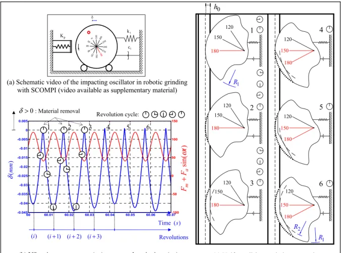
Figure 2.4 SDOF response using typical parameters: ke =163kN m, 3 2 4911 10 c k = × kN m , 4fn = Hz, kt =17.2kN m, 27 t m = kg, ξ =0.1, 80Fm= N, 0.2mu = kg, e=0.5mm, 6000rpm Ω = , E=6.8mm, ε =0.02mm, 0.33μ = . ... 25
Figure 2.5 Angular position of cutting impacts and uniform disk wear in robotic grinding ... 27
Figure 2.6 Test setup using the angular sampling technique ... 31
Figure 2.7 Disk with angle markings, bump, balancing protrusion and edge painted white ... 34
Figure 2.8 Paint removal after single-pass robotic grinding ... 35
Figure 2.9 High-speed video (2500 fps) of imposed cutting impacts (video available as supplementary material) ... 36
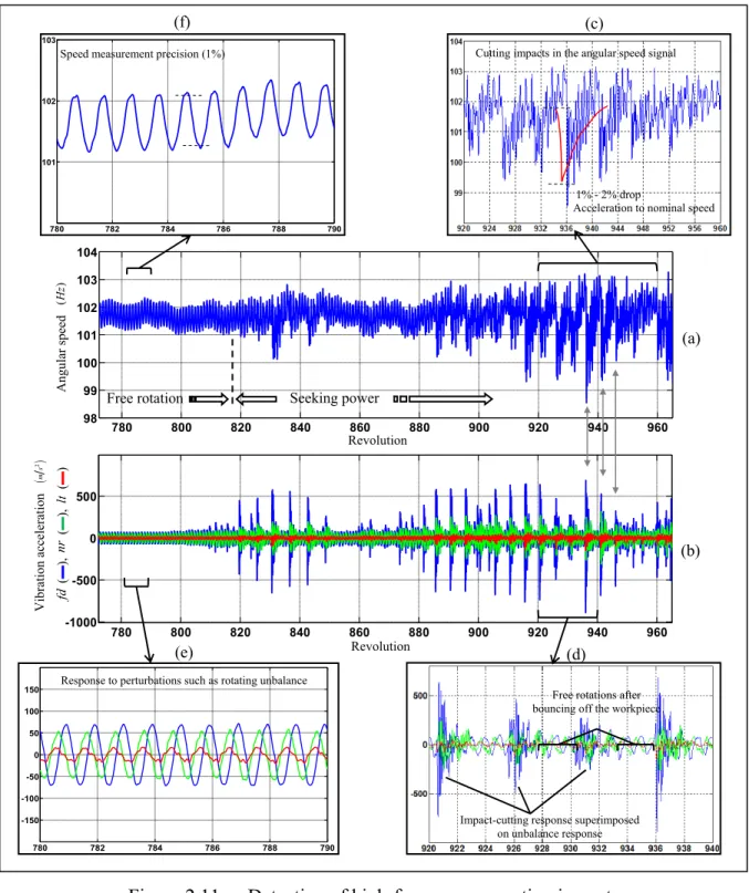
Figure 2.10 Triaxial vibrations (feed fd , normal nr, lateral lt) and rotational frequency in single-pass grinding (overview) ... 38
Figure 2.11 Detection of high-frequency repeating impacts in robotic
grinding (detailed views) ... 39 Figure 2.12 Impact-cutting map from the speed signal ... 41 Figure 2.13 Impact-cutting map from the speed signal based on the
experiment with the bump showing (─) a major regime of 2
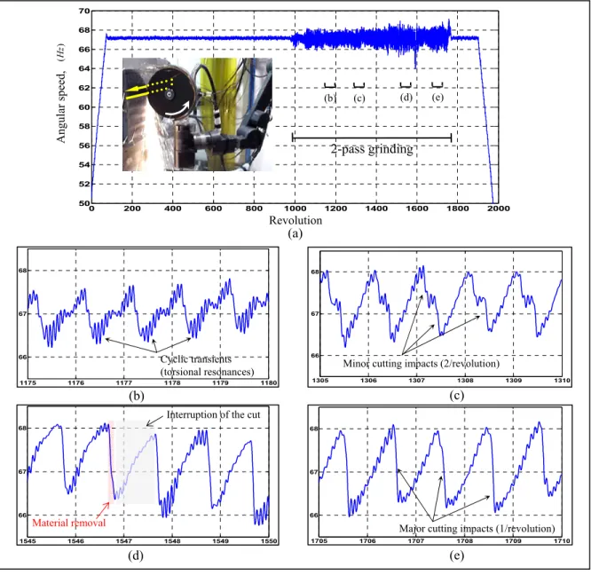
impacts/revolution and (…) minor oscillations ... 42 Figure 2.14 Discrete cutting events from rotational speed measurements
in Test (2) at 4000 rpm ... 45 Figure 2.15 Discrete cutting events from rotational speed measurements
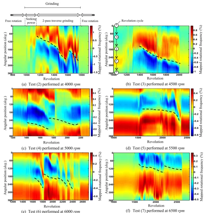
in Test (6) at 6000 rpm ... 46 Figure 2.16 Impact-cutting maps showing the moving angular position of
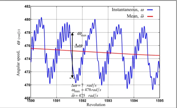
cutting impacts ... 47 Figure 2.17 Typical values of ω, ωmax and Δω during a cutting impact
from measured rotational frequency in Test (3) at 4500 rpm ... 51 Figure 2.18 Percentage drop in speed during the impacting regime for the
tests listed in Table 2-3 ... 51 Figure 3.1 Vibration dynamics in an industrial robotic task ... 56 Figure 3.2 Vibro-impact dynamics adapted from (Comparin and Singh,
1989) ... 58 Figure 3.3 Qualitative investigation of the permanent regime of material
removal using typical parameters: fn =6Hz, 33mt = kg,
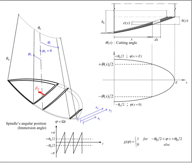
2 46.9 t t n k =mω = kN m, ξ =0.1, Δ =l 8mm, h0 =0.2mm, 3 0.024 10 mm ε = × − , E=6.8mm, 0.6 u m = kg, e=0.5mm, 0.2744 μ = , ke=163kN m, 4911 103 2 c k = × kN m ... 60 Figure 3.4 Kinematics of traverse robotic grinding adapted from (Hazel
et al., 2012b) ... 64 Figure 3.5 The uncut chip ... 65
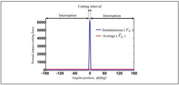
Figure 3.6 The uncut chip and differential elements... 67 Figure 3.7 Impact cutting at a given angular position of the grinder shaft ... 69 Figure 3.8 Instantaneous impact-cutting force FN( , )ϕ h0 and the average
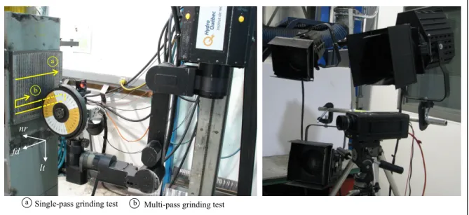
grinding force F h required to remove the uncut chip N( )0 (h0 =0.2mm, E=7.6mm, R0 =100mm,μ=0.33, 163 e k = kN m, 4911 103 2 c k = × kN m , vfd =80mm s, 6000rpm Ω = ) ... 71 Figure 3.9 Experimental setup and data acquisition system ... 73 Figure 3.10 Robotic grinding test rig with high-speed camera and lighting ... 74 Figure 3.11 Simplified control mechanism of SCOMPI in robotic
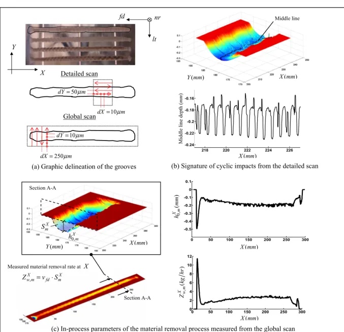
grinding ... 75 Figure 3.12 AltiSurf 530 machine ... 77 Figure 3.13 Topographical inspection of the grooves created by
single-pass grinding tests ... 78 Figure 3.14 High-speed video recorded in the middle of the grinding pass
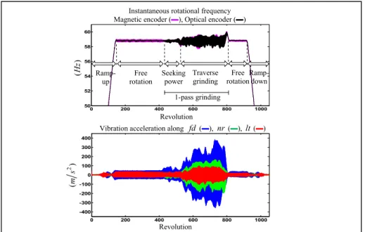
(video available as supplementary material) ... 83 Figure 3.15 Overview of the measured instantaneous rotational frequency
and tri-axial vibrations in Test 13 at 3500 rpm (typical of
single-pass robotic grinding tests) ... 84 Figure 3.16 Impacting dynamics of material removal from the measured
instantaneous rotational frequency in Test 11 at 4500rpm ... 85 Figure 3.17 The cyclic impacting oscillations from tri-axial vibrations and
instantaneous rotational frequency measured in Test 8 at
6000rpm ... 86 Figure 3.18 Signature of the impacting dynamics on the ground surface
Figure 3.19 Experimental determination of the edge and cutting force
coefficients, ke and kc ... 88
Figure 3.20 Measurements of grinding power and material removal rate
along the groove’s longitudinal axis ... 91 Figure 3.21 Application of the impact-cutting model to achieve a target
depth of cut in robotic grinding ... 92 Figure 4.1 Chatter marks on the ground surface under certain conditions
of robotic grinding with SCOMPI ... 95 Figure 4.2 Impact testing on the robot’s end-effector in an average
grinding configuration ... 99 Figure 4.3 Robotic machining on the stability chart ... 101 Figure 4.4 Regenerative chatter as a feedback loop ... 102 Figure 4.5 Revisiting the problem of regenerative chatter for robotic
grinding ... 103 Figure 4.6 Stabilized tool holder’s structural response to impact-cutting
excitation ... 104 Figure 4.7 Unstable impact cutting ... 106 Figure 4.8 Practical margins of stable grinding with SCOMPI from
numerical simulation (ωd =4.8Hz, 21mt = kg, ξ =0.0306, 0 100 R = mm, E=7mm, ke =148kN m, 3 5910 10 c k = × kN m, λ=0.9) ... 109 Figure 4.9 Practical importance of the borderlines of stability in
machining taken from (Merritt, 1965) ... 110 Figure 4.10 Marginal gain values for robotic grinding with SCOMPI from
(―) Conventional chatter analysis (―) Impact-cutting
regenerative chatter analysis ... 112 Figure 4.11 The working point for Tests 14-24 on the stability chart ... 115
Figure 4.12 Visual inspection of the grooves created in Tests 14-24 for
surface deterioration ... 116 Figure 4.13 Deterioration of the regular impact-cutting pattern caused by
regenerative chatter in Tests 14-24 ... 117 Figure 5.1 Track-based kinematic architecture of SCOMPI with 6-DOF ... 124 Figure 5.2 Simulated FRF plots for SCOMPI with sinusoidal
disturbance excitation along x ... 1260
Figure 5.3 Configuration of SCOMPI for modal testing experiment ... 127 Figure 5.4 Analytical and experimentally measured mode shapes (modes
1-3) ... 128 Figure 5.5 Analytical and experimentally measured mode shapes (modes
4-6) ... 129 Figure 5.6 Vibrations correlated to the articulated degrees of freedom in
a robotic cutting process ... 130 Figure 5.7 Mode shape measurement on the robot structure ... 132 Figure 5.8 FRF sum and MIF for 33 measurement channels of the
experimental modal test on SCOMPI ... 133 Figure 5.9 The eigendirections
{ }
Ψ 1,{ }
Ψ 2 and{ }
Ψ 3 of an articulatedNOMENCLATURE
i
a DH parameter associated to link (i) of the robot ( )m 0
A cross-sectional area of the cut (m2)
Ai transformation matrix from link (i) to (i-1)
b dead zone ( )m
t
c damping coefficient of tool holder (N s m⋅ )
power
C cost of fitting the model on measured power (%)
[ ]
C joints’ damping matrix for the robot (N s m⋅ ) or (N s rad⋅ )i
d DH parameter associated to link (i) of the robot ( )m dt integration time step ( )s
dx width of a differential element ( )m
dX resolution of graphic delineation along X (μm) dY resolution of graphic delineation along Y (μm)
D damping coefficient of the Impact-Pair (N s m⋅ )
[ ]
D robot’s inertia matrix (N s m⋅ 2 ) or (N s rad⋅ 2 )e eccentricity ( )m
E grinding wheel (cutter) width ( )m
c
E energy per impact ( )J
r
E rotational kinetic energy ( )J
f instantaneous rotational frequency (Hz)
cl
f counter clock’s frequency (Hz)
d
f feed direction of the grinding task
ml
f mean line rotational frequency (Hz)
mp
f mapped rotational frequency (Hz)
n
f robot’s first mode natural frequency (Hz)
rst
f piecewise linear restoring force function ( )N
rstL
f linear restoring force function ( )N
rstN
f nonlinear restoring force function ( )N F force ( )N
a
F alternating external force ( )N
c F cutting force ( )N e F edge force ( )N ex F external force ( )N m
F mean external normal force ( )N
N
F instantaneous normal grinding force ( )N
N
F average normal grinding force ( )N
,
N E
F error in the average normal grinding force ( )N
,
N m
F measured average normal grinding force ( )N
T
F instantaneous tangential grinding force ( )N
T
,
T m
F measured average tangential grinding force ( )N
{ }
g vector of gravitational generalized force ( )NG real part of the receptance frequency response function (m N)
h depth of cut ( )m
0
h target depth of cut ( )m
0,Xm
h measured depth of cut at X ( )m
H imaginary part of the receptance frequency response function (m N)
i
H height of the rectangular prism assumed as link (i) of the robot( )m i spindle revolution index
I infeed distance (mm)
Ii tensor of inertia for link (i) of the robot expressed in its attached frame (kg m⋅ 2)
J moment of inertia (kg m⋅ 2)
[ ]
J jacobian matrix of the robot[ ]
Jv link’s sub-Jacobian matrix for transformation of linear velocities[ ]
Jω link’s sub-Jacobian matrix for transformation of angular velocitiesc
k cutting force coefficient (N m2)
e
k edge force coefficient (N m)
t
k stiffness coefficient of the tool holder (N m)
K stiffness coefficient of the Impact-Pair (N m)
p
K process stiffness (N m)
[ ]
K joints’ stiffness matrix for the robot in (N m) or (N rad)l spring length ( )m
i
l length of link (i)
lt lateral direction of the grinding task
i
L length of the rectangular prism assumed as link (i) of the robot( )m m filter length (revolutions)
i
m mass of link (i) for the robot ( )kg
t
m equivalent mass of the tool holder ( )kg
u
m unbalance mass ( )kg
M equivalent mass of the Impact-Pair ( )kg
I
M ,MII masses of the Impact-Pair ( )kg n number of samples per revolution
c
n number of impacts per revolution
cl
n number of clock’s counts per pulse period
nr normal direction of the grinding task
tst
n number of tests
N rotational frequency (Hz)
m
N measured rotational frequency (Hz)
{ }
ji
O position vector for the origin of frame (i) expressed in frame (j) ( )m p grinding wheel profile ( )m
{ }
p angular displacements of rotors’ actuators (deg)P grinding power ( )W
E
P error in grinding power ( )W
m
P measured grinding power ( )W
m
P mean measured grinding power ( )W
X m
P measured grinding power at X ( )W
Pc position of center of masses for the six links of the robot ( )m i
q robot’s ith degree of freedom
{ }
q robot’s configuration ( )m or (deg){ }
Q vector of generalized forces ( )N{ }
rc i, position vector for the center of mass of link (i) ( )m R grinding wheel radius ( )m0
R rear radius of the grinding wheel (x=0) ( )m
0,m
R measured rear radius of the wheel (x=0) ( )m
Ri rotation matrix from link (i) to the base frame
S measured signal
chip
S surface of the uncut chip (m2)
f
S filtered signal
X m
S groove’s cross-sectional area measured at X (m2) t time ( )s
T revolution period of the grinding wheel ( )s
Ti transformation matrix from link (i) to base frame (0) fd
v feed speed of the robot
( )
m s{ }
vc i, vector of linear velocity of the centre of mass for link (i) of the robot( )
m s{ }
ji
v vector of linear velocities for the origin of frame (i) expressed in frame (j)
( )
m s V volume of the rectangular prism assumed as link of the robot(m3)chip
V volume of the uncut chip (m3)
s
V peripheral speed of the grinding wheel
( )
m s w width of cut ( )m0
w target width of cut ( )m
i
W width of the rectangular prism assumed as link (i) of the robot( )m x coordinate along the grinding wheel width ( )m
0
x base frame coordinate for the robot
X longitudinal coordinate of the groove ( )m y position coordinate of the robot ( )m
0
y base frame coordinate for the robot
ave
y average robot’s displacement ( )m
E
y position coordinate of the robot’s base ( )m
std
Y traverse coordinate of the groove ( )m
0
z base frame coordinate for the robot Z normal coordinate of the groove ( )m
d
Z wear rate of the grinding wheel (m s3 )
w
Z material removal rate (m s3 ) ,
w m
Z measured material removal rate (m s3 ) ,
X w m
Z measured material removal rate at X (m s3 )
{ }
0i
Z axis of joint (i) expressed in the base frame
α normalized slope (N m)
αi DH parameter associated to link (i) of the robot (deg)
β proportional damping coefficient
δ deflection ( )m
I
δ ,δII displacements of the Impact-Pair ( )m
Δ wheel’s advance per revolution ( )m l
Δ pre-compression ( )m
B
y
Δ position displacement of the robot ( )m
ε chip thickness ( )m
ε average chip thickness ( )m
ξ damping ratio of the robotic holder (%)
η phase difference between undulations on the machined surface (deg)
θ cutting angle (rad) 0
θ cutting angle at the wheel’s rear (x=0)(rad)
λ overlapping factor
μ friction coefficient
ρ ratio of cut
τ passing period of the cutter ( )s
ϕ angular position of the grinder shaft (rad)
Φ receptance frequency response function (m N)
{ }
Ψ i robot’s eigendirection for the vibratory degree of freedom associated to the ith articulation ω rotational frequency (rad s)ω mean line rotational frequency (rad s)
c
ω chatter frequency (rad s)
{ }
ωc i, vector of angular velocities of the centre of mass for link (i) of the robot{ }
ji
ω vector of angular velocities for the origin of frame (i) expressed in frame (j)
( )
m sd
ω robot’s first mode damped natural frequency (rad s)
n
ω robot’s first mode natural frequency (rad s) 01
T
ω − NI-I transition frequency (rad s) 01
T
ω + I-NI transition frequency (rad s)
INTRODUCTION
The elastic components in a machine tool structure respond to internal and external forces of the machining operation with finite deformation amplitudes. Lack of dynamic stiffness in the machine tool, the tool holder, the cutting tool and the workpiece material causes free, forced and self-excited vibrations in response to perturbations. Robotic tool holders, employed recently in the manufacturing sector, provide holding mechanisms typically two to three orders of magnitude more compliant than the rest of the chain. Moreover, modal properties of the articulated multi-body robot structure, unlike the conventional tool holder, vary substantially as the robot undergoes through the machining trajectories accessing awkward locations. Tremendous decrease in the dynamic stiffness and its configuration-dependent modal characteristics make the problems of vibrations and instability of particular concern in robotic machining. Machinists should then plan their tasks in presence of significant vibration amplitudes even if stability is guaranteed. Vibration problems encountered in a machining operation performed by a robot arm are more severe compared to CNC machining.
The high force task of machining is not much developed for robotic tool holders. Instead, robots provide maneuverability into machining operations which cannot be performed by traditional CNC machines on complex geometries, large parts or in hard-to-reach areas. This has come at the cost of tool holders with two distinct characteristics being (i) substantial compliance, and (ii) configuration-dependent structural dynamics. The vast literature about vibrations and instability in machining operations since the beginning of the 20th century has
not focused on the vibratory dynamics that result from these particular properties. That is because even within the modern industries which are heavily dependent on robots, machining products constitute less than 5% of robotic sales (Chen and Dong, 2013). Robots were not believed to be able to replace CNC machine tools but they are emerging as a viable alternative depending on the required surface finish. There exist applications where a robotized approach for the task of material removal is one of the best practical solutions available. An example of such cases is the robotic grinding application under development at
Hydro-Québec’s research institute (Hazel et al., 2012b) which is used in this study. The new application is being developed in order to robotize the field maintenance tasks and construction work on hydropower equipment. The tasks of material removal address issues such as cavitation damage and cracking. They are usually performed in awkward locations or hard-to-reach areas and on large/complex geometries. The robotization of such tasks saves the great costs of disassembly for off-site repairs. Also, within the manufacturing sector, turbine runner manufacturers have succeeded to automatize the machining of the blades with very large 5-axis CNC machines, but the welding and grinding operations are still performed manually. A major difficulty in robotizing the grinding application has been the inherent significant vibrations during the process. To deal with this challenge, a strategy of controlled material removal rate is employed rather than position control which is generally used in rigid machine tools performing conventional grinding. The strategy relies on an average model of the vibratory oscillations in the cutting force during material removal.
Including the vibratory dynamics in the planning of the tasks for robotic processes appears to be necessary if productivity in robotic machining processes is to be enhanced. Chatter, which is always a limitation to productivity and part quality, remains an important topic in the robotized manufacturing research as well. The persistent relevance has always been due to the complexity of the phenomenon which makes its understanding nontrivial. The intuitive approach is to understand the steady vibratory oscillations present in the material removal process first, and then, to investigate the mechanisms of instability. Therefore, a study of robotic machining chatter should be established on the basis of the vibratory dynamics specific to a robotic tool holder.
Objective of this Work
The objective of this work is to understand the vibratory dynamics specific to the robotic grinding process under study in order to investigate instability based upon appropriate understandings of the governing vibrational behavior. Ultimately, the line of research will result into chatter predictive models which will be employed to predict unstable conditions
during the grinding tasks performed by the robot manipulator. Without chatter predictive models, task planning involves conservative selection of cutting parameters through trials and errors resulting into loss of productivity. Modeling tools, experimental procedures and understandings which are developed to reach this objective can be implemented into the control strategy of the robotic machining operation under study in order to improve the accuracy of the robotized material removal tasks.
The research work is conducted on a robotic grinding process specifically. However, the principal understandings developed throughout the work can be extendable for other robotic machining operations.
Organization of the Thesis
Two separate lines of research are conducted in this study toward reaching the objective mentioned in the previous section. Given the fact that chatter is the issue of unstable interactions between the dynamics of the cutting process and the tool holder’s structural
dynamics, these two research aspects are considered accordingly. The main emphasis is
though put on the vibratory dynamics of the cutting process affected by the substantial compliance of the robot arm through the work presented in Chapters 2, 3 and 4. The configuration-dependent structural dynamics of the robotic tool holder is studied in Chapter 5.
Following this introduction, Chapter 1 presents a review on some available literature about machining with flexible manipulators and addresses the critical issues encountered in this field. The robotic machining technology used for this study is also presented. The chapter finishes by a brief description about the problem of chatter in machining as it is the required background for the reader of this thesis.
In Chapter 2, the instantaneous cutting process is studied through modeling and experimental validations in order to understand the vibratory regime which results from the substantial
compliance of the grinder robot. Cyclic impacting oscillations of the cutter during material removal (impact cutting) are captured with the help of the experimental setup and the procedures developed in this chapter. The setup employs the methodology of angular sampling to locate the interruptions of the cut and to investigate the governing dynamics. Variation in the measured instantaneous rotational frequency of the spindle during the cutting impacts, at every revolution, is correlated to the grinding power. The significance of such real-time measurement during grinding is that it can be used as feedback to control the rate of the material being removed. However, one missing element is a model which formulates the grinding force or power to be delivered at the spindle for achieving a target material removal rate, in presence of the sustained impacting oscillations in the process.
A model for the grinding power based upon the impact-cutting behavior is presented in Chapter 3. First, to complement the experimental study presented in Chapter 2, a conceptual analogy is drawn between the impact-cutting behavior and the vibro-impact dynamics of the classical generic impact pair. This is to assure that the dynamic behavior is an inherent characteristic of the process. With this understanding and the averaged impact-cutting model for grinding power considered into the control strategy of the robotic grinding task, this chapter investigates whether metal removal at a target material removal rate or to a target depth of cut is possible given the unavoidable severe vibrations inherent to the process. The capability of the impact-cutting model to predict grinding power in the real practice of the robot is validated as long as stable grinding conditions are guaranteed.
Regenerative self-excitations that originate from the cutting process within the impact-cutting material removal are studied in Chapter 4. Vibro-impact motions of the grinding disk introduce discrete kinematics into the dynamics of the grinding process under study. This makes the grinding operation different from conventional grinding which has continuous kinematics and involves irregularities. The cutting impacts which occur mainly once per spindle revolution and remain quasi-stationary regarding their angular position bring regular kinematics into the cutting process. Stability of metal removal, which is thus carried out more similar to the flutes of a milling cutter, is analysed with the help of the stability lobes diagram
used generally for milling operations. The process is simplified by a SDOF dynamic model of the robotic holder. A single delay term that accounts for the self-excitation from the overlapping cutting impacts once per spindle revolution is considered. An appropriate perspective for the problem of regenerative chatter in robotic machining is drawn by using the specific vibratory dynamics of the process, i.e. the impacting oscillations. An experimental investigation is also carried out to support the part of the study presented in this chapter. This is the first step toward predictive models for avoiding regenerative chatter in the robotic grinding process under study.
The second line of research, focused on the robotic tool holder’s structural dynamics, is presented in Chapter 5. The objective is to develop the modeling tool and the needed insight for vibration analysis of a robot arm with varying vibratory dynamics caused by its extensions and compressions when accessing awkward locations along machining trajectories. Traditional modal analysis is extensively employed in the studies of vibrations and instability for machining. Nevertheless, unlike the fairly invariant structure of a CNC machine tool holder, modal properties of a robotic holder vary substantially. A multi-body dynamic model is developed in this chapter for the varying articulated structure of the robot arm. The model is validated through experimental modal analysis by measurement of the natural frequencies and mode shapes. A discussion is provided about defining eigendirections for the robot structure to replace the functionality of mode shapes in conventional modal analysis. Instability due to self-excitations caused by the exchange of vibration energy between structural modes can be well investigated using this proposed approach.
Contributions and industrial impacts of the thesis are summarized at the end and some recommendations are made about how this research work can be continued in future.
CHAPTER 1
Background and Literature Review
1.1 Machining with Flexible Manipulators
The manufacturing procedure for many industrial parts includes cleaning, pre-machining, machining for high tolerance surfaces, painting and assembly. Robotization of these operations became desirable firstly in order to avoid manual operations in extremely noisy, dusty and unhealthy environments. However, there exist instances where machining is not even possible using the conventional CNC machine tools. Machining of large parts or parts with complex geometries are examples of such instances. Due to variations and irregularities of machining trajectories, these are considered as high-cost difficult-to-change capital investments for a CNC machine tool cell where a robotic machining cell becomes the immediate viable alternative. In a robotic machining process, a light-weight cutter or grinder is held by an articulated robot arm. Material removal is achieved by the rotating cutting tool while the robot end effector ensures that the tool follows a programmed trajectory in order to work on complex curved surfaces. However, more than 80% of the processes developed for industrial robots are about material handling and welding (Zhang et al., 2005). Machining processes are high force tasks in which the physical contact of the cutter with workpiece material causes large deformation errors on the robot arm. The process of metal removal requires a process-specific force to be exerted in order to establish the shear deformation of work material and remove the chip. Constant conservative feed-rate and depth of cut is the solution of robot machinists to reduce vibrations during the operation. Few robots have been reported successful to perform machining.
Some practical issues on a milling application performed by an industrial robot are discussed in (Marui et al., 1988c). An analytically based stiffness model of a robot structure in its
workspace for the special needs of a machining application is presented by (Abele, Weigold and Rothenbucher, 2007). Dynamic interactions of a flexible multi-body model for the robot structure with a process model for a milling application is presented in (Marui et al., 1988a). The purpose has been to predict the tool displacement caused by the process forces. Research on robotic deformation compensation is mainly about gravity compensation and deflection compensation. Not much attention has been given to process-force induced robot deformation (Zhang et al., 2005). Modeling and experimental identification of the robot within its working space is used by (Zhang et al., 2005) to estimate and compensate for the real time deformations and improve the overall machining accuracy. A tool angle adjustment method in a grinding application with a small robot is introduced by (Akbari and Higuchi, 2000; Akbari and Higuchi, 2002). Using real-time force control, (Matsuoka et al., 1999) studies the characters of a robot in milling to avoid large process forces. Much effort has been made by force control. The idea was to move the robot by the information of contact forces (Ferretti, Magnani and Rocco, 1999). Regarding process development (Abele, Weigold and Kulok, 2006) uses high speed cutting to reduce the process forces so that the load on the structure is minimized. Stability investigation of the process has also been done in a few recent studies (Pan et al., 2006; Pan and Zhang, 2007). Critical issues and challenges about using a robotic arm as the tool holder to perform machining are reviewed by (Wang, Zhang and Pan, 2006).
1.1.1 The SCOMPI1 Robot
Despite serious challenges that exist about vibration and instability in robotic machining processes, the maneuverability that robots bring into the operations makes them, sometimes, the only practical solution for machining. The robotic machining technology which is used in this study (Hazel et al., 2012b) provides maneuverability in order to automate the in-situ maintenance work on hydroelectric equipment. The 6-DOF robot called “SCOMPI” shown in
(b) Grinding between the blades of a Fransic turbine runner 2 q 3 q 4 q 5 q 6 q 1 q
(a) Track-based kinematic architecture of SCOMPI with 6-DOF
Figure 1.1 The SCOMPI robot
Figure 1.1.a was developed at Hydro-Québec’s research institute, IREQ2. It uses a lightweight structure (≈30 kg ) which is much lighter than the average robot used for machining (≈200 kg ) to provide a portable solution for field machining tasks, thus avoiding the costs of dismantling parts and minimizing shutdowns. The manipulator’s unique kinematic design uses a track-based installation for its first prismatic joint rather than being installed on a rigid grounded shoulder like the robots used in factory lines. The track may be straight, circular or a series of circular sections so that such feature provides a track-long
extended working envelop to gain access for machining awkward locations. Such intervention
works as welding, grinding or machining which workers cannot do in these locations are done by the fully extended arm and with the help of its track-based kinematics. Several field repair and construction procedures on large hydropower equipment are under development
with this robotic machining technology (Hazel et al., 2012a). Grinding tasks performed by SCOMPI are demanding jobs that involve heavy material removal aimed at modifying parts’ dimensions (Hazel et al., 2012a) rather than generating glossy surfaces only. The task shown in Figure 1.1.b is about reshaping the blades of old-design Francis turbine runners to correct fluid flow problems (Giroux et al., 2008). Such maintenance operation involves thickening of the blades at some sections by overlay welding and thinning at other sections by grinding. There exist instances that 18 mm depth of material over a 1 m area needs to be removed by 2
the robotic grinding process through several iterations reaching typical material removal rates around 4-5 kg h. In applications of the robot for refurbishment of head gate components (Gagné et al., 2010), few millimeters of material are removed over an area of 10 m length, 200 mm width. The problems of vibration and instability encountered during machining with this robot are even more serious compared to the average machining robot. This is the price to pay for being capable to machine in hard-to-reach areas while using a portable robotic solution as well.
Robotic machining has been reported by many researchers to be more prone to severe chatter vibration problem as compared to CNC machining. There are not guidelines or rules of thumb for robot machinists to set up their task in a way to avoid chatter. This has resulted into the frustrated trial and error effort spending a lot of time to find the appropriate chatter-free machining operation setup, which may sometimes even be at the expense of loss of productivity.
1.2 Machining chatter
The well-known problem of machining chatter is briefly described in the current section. Machining chatter is the issue of self-excited vibrations in the process of removing material resulting into unwanted machining conditions such as excessive noise, disproportionate tool wear and breakage or poor surface quality. There exist an extensive literature about investigation and avoidance of chattering conditions in machining started by the early studies of (Arnold, 1946), (Hahn, 1953) and (Doi and Kato, 1956). A comprehensive mathematical
model and analysis of the problem was first given by (Tobias and Fishwick, 1958) and (Tlusty and Polacek, 1963). The excitation energy under the chattering condition comes from the cutting process itself. Several mechanisms of self-excitation have been recognized throughout years of research continued until very recent studies (Quintana and Ciurana, 2011; Siddhpura and Paurobally, 2012). A classification of these mechanisms distinguishes frictional, regenerative, mode coupling and thermo-mechanical chatter (Wiercigroch and Budak, 2001). Among all, instability due to the regeneration of surface waviness and the mode-coupling instability are considered as two dominant mechanisms.
1.2.1 Regenerative Chatter
Overlapping cuts exist in almost all machining operations. The tool is always cutting a surface which was already cut during the previous tool passes. Regeneration is the feedback mechanism between subsequent cuts as shown schematically by the illustration in Figure 1.2. Oscillations of the cutting tool leave undulations on the machined surface. The excitation due to the cutting force F depends on the instantaneous chip thickness c h. The uncut chip thickness h is modulated by the oscillations of the cutting tool in the current and previous 0
passes ( )y t and (y t−τ) with τ being the passing period of the cutter (delay term). The phase difference η between the undulations left on the surface cause perturbations in the
0 h h ( ) y t ( −τ) y t y c F η
cutting force which results from chip removal. Under certain conditions of the cutting operation, perturbations in the cutting force can grow exponentially and as a result, the vibration response to cutting force excitation becomes unstable. Numerous researchers such as (Altintas and Budak, 1995) have formulated the interactive dynamics resulting into such unstable conditions in machining with the help of linear delay differential equations (DDE). The formulation combines the dynamics of the cutting process with the tool holder’s structural dynamics. Solving the DDE, the borderline of stability is plotted versus the spindle speed of the operation in charts known as “stability lobes diagram”. As shown in Figure 1.3, in the stability lobes diagram, the borderline of stable operation is plotted versus a cutting parameter such as the width or the depth of cut. These charts are considered as guidelines for machinists in order to setup the working point for the task in the white region below the lobes where cutting is predicted to be stable.
Unstable Stable cutting Spindle speed C ut ting par am et er
1.2.2 Mode Coupling Chatter
The mechanism of mode-coupling instability in machining occurs in vibratory systems which are assumed to have at least two degrees of freedom. It was first introduced by (Tlusty and Polacek, 1963) as the “positional coupling” principle causing self-excitation in machining operations. The effect is briefly described in this section.
In the cutting operation shown in Figure 1.4, the system is assumed including two natural vibratory modes along directions I and II. The vibrations of the system along one direction occurs with a phase shift relative to the vibrations along the other direction. The result is that the cutting tool which is connected to the vibratory system, moves on an eliptical path. This has also been observed experimentally (Hahn, 1953). Let’s assume that the oscillations in the cutting force F is proportional to the vibrations along the normal direction y to the c
workpiece. Considering the moving direction as depicted on the ellipse shown by Figure 1.4, during the first half of the move from point A to B, the movement direction of the tool tip is in the opposite direction of the cutting force. This means energy is dissipated from the vibratory system during this part. Within the second half cycle though, the cutting force has a projection in the same direction as the movement of the tip. This means energy is delivered into the system during this half. Given the fact that during the second half the cutter is
c F I. II. A B c F I. II. y Increasing depth of cut
Figure 1.4 Mode-coupling instability in machining adapted from (Tlusty and Polacek, 1963)
removing greater depths of material, the work done is bigger and the resultant in one oscillation cycle is that energy is exerted into the system. It is therefore obvious that orientation of the natural vibratory modes of the system with respect to the direction of the cutting forces is very important regarding the self-excitations due to the mode-coupling effect. The layout of these directions with respect to the direction of the cutting force defines if the system becomes unstable caused by the mode-coupling effect.
1.2.3 Forced vibration
In self-excited vibrations with mechanisms such as regeneration or mode-coupling, as described in Sections 1.2.1 and 1.2.2, the alternating force which sustains the motion depends on the motion itself. That means the force magnitude is a fuction of the cutter’s vibratory deflection and if the motion stops, the alternating force disappears. Another type of vibration involved in metal cutting is caused by the forces which are independent of the cutter’s motion and persist if the vibratory motion stops. These are forced vibrations caused by the perturbing forces present in the mechanical system such as forces due to the rotary operation, forces induced by hydraulic devices integrated into the machine or floor vibrations. For the case of grinding, vibrations caused by the unbalance and eccentricity of the wheels are the fundamental perturbing forces of the rotary operation.
From the brief introductions about the two mechanisms of slef-excitation in the preceding sections, it can be seen that vibrational instability in machining is investigated based upon appropriate understanding of the vibrations that govern the steady regime of metal removal. To study regenerative instability, one should first have enough knowledge about the vibration locus of the cutter’s end during the steady regime of material removal. For an investigation of mode coupling instability, vibratory modes of the machine tool structure should have been identified first. In this thesis, first, the steady vibratory dynamics of the robotic grinding process is investigated through Chapters 2 and 3. In Chapter 4, the mechanism of regenerative chatter affecting the steady vibrations of the operation is studied. The part of the
work which is presented in Chapter 5 is focused on the vibratory dynamics of the multi-body articulated structure of the robotic tool holder in machining.
CHAPTER 2
Angular Analysis of the Cyclic Impacting Oscillations
In this chapter, the instantaneous cutting process performed by a grinder robot arm is investigated with the help of modeling and experimental verifications. The purpose is to elaborate the effect of the substantial compliance of the tool holding mechanism, i.e. the robot arm, on the dynamics that govern the process of material removal.
2.1 Introduction
The tool holder, in a machining task, assures that the cutting tool follows the programmed trajectory of machining. In the meantime, it also provides restoring forces in order to counterbalance the cutting force which is established inside the zone of contact. Once this balance is violated, disengagement of the cutter with the workpiece takes place and the cut gets interrupted. In CNC machining, the elements in the machine tool-tool holder-cutting tool-workpiece chain have the same order of magnitude stiffness. Therefore, the capacity for providing a counterbalancing force at the contact zone is high. Contact is thus almost always maintained as long as large unstable vibrations are not met. For a robotic arm though, this force capacity is very small as compared to the amount of force required for removing material. The limit is dictated by the compliant restoring mechanism of the robot arm which is composed of articulated bodies. Compliance of a robot is reported mainly due to its joints’ compliances (Zhang et al., 2005). This is caused by the elasticity of gear transmission systems used for the articulations. Dependent on the type of the robot and its size, gears’ compliance can contribute from 50% to 75% of the overall robot’s compliance (Abele, Weigold and Rothenbucher, 2007). Also, in the parallel mechanism of a CNC machine, the off-axis flexibilities of articulated joints are constrained by the effect of other chains and the closed-loop mechanism is stiff in overall. In the open kinematic structure of a serial robot though, the chain becomes progressively less rigid with multi-body components added. This
also contributes to the very compliant restoring mechanism of a robot for the high-force task of machining. A typical articulated robot has a stiffness usually less than 10 kN m , while a 3
standard CNC machine very often has stiffness greater than 50 10 kN m× 3 (Zhang et al.,
2005). In the case of the SCOMPI robot used for this study, the stiffness value is around 20 kN m. Robotic tool holders are thus, one to three orders of magnitude more compliant than the conventional CNC machine tools, inherent to their structure. This makes robotic machining a striking example of intermittent cutting because a robot can hardly afford the counterbalancing force required at the cutting zone due to its limited force providing capacity.
Interruption of the cut is an issue of great concern in the study of the dynamics of material removal because it introduces nonlinearity into the system dynamics and results into non-uniform metal removal. Researchers have developed different methodologies to deal with it. The interruption phenomenon is recognized as the basic nonlinearity in machining chatter (Tlusty and Ismail, 1981) and a traditional approach is to deal with it in numerical simulations by setting the cutting force to zero when the tool moves out of the cut. Modern cutting operations involve conditions where the degree of such nonlinearity is increased and the tool cuts the material for only small fractions of the spindle period. High-speed machining of contoured surfaces, near-net-shape flexible components and difficult-to-machine materials are examples of such operations (Davies et al., 2000). A generalized analytical approach is proposed (Bayly et al., 2003; Davies et al., 2000; Davies, Pratt and Dutterer, 2002; Szalai and Stepan, 2006) by denoting a parameter 0< < which represents ρ 1 the ratio of time spent cutting to not cutting during a spindle period. The stability of interrupted cutting is then investigated for scenarios both of continuous operation (ρ≈ ) and 1 of highly interrupted operation (ρ≈ ). In this chapter, interruptions of the cutting process 0 are investigated experimentally with respect to the instantaneous angular position of the spindle. This enables us to correlate the intermittence in the cutting operation with the machine cycle, i.e. the spindle revolution and draw conclusions about the governing dynamics. The angular analysis technique has been used successfully in a large number of
applications to observe faults in rotating machines with discrete events during rotations (Girardin, Rémond and Rigal, 2010; Remond and Mahfoudh, 2005; Stander and Heyns, 2005; Yang et al., 2001). The technique is applied in this study to detect and locate the angular position of the discrete cutting events per spindle revolution.
In the following section, dynamic modeling and numerical simulation of the robotic grinding process is presented in order to explain, theoretically, the governing dynamics of the material removal process. In Section 2.3, the test setup and material used for verifying these governing dynamics are described. The techniques of angular sampling and analysis with the measurement of instantaneous rotational frequency which are the key features implemented in the test setup are described in this section. The experimental approach is then evaluated in Section 2.4 regarding its capability to detect and locate the discrete cutting events of an imposed interrupted cutting operation. Robotic grinding experiments are then studied in Sections 2.5 and 2.6 using the experimental setup developed. The work presented in this chapter is mainly focused on experimental characterization of the cutting dynamics performed by the compliant robot arm. Dynamic modeling and analysis is thus simplified to a SDOF representation.
2.2 Impact-Cutting Material Removal in Robotic Grinding
Details of a typical robotic grinding task are studied in this section to illustrate the distinctive vibratory dynamics of the process theoretically.
2.2.1 SDOF dynamic model
A SDOF representation of robotic grinding with a flexible arm is shown in Figure 2.1. The robot holds the cutting tool, approaches the workpiece along coordinate yB and positions the grinding wheel (see Figure 2.1.b). Traverse grinding is then performed through robot travel in feed direction fd parallel to the wheel axis (see Figure 2.1.a). Restoring and damping