HAL Id: hal-00924123
https://hal.inria.fr/hal-00924123v2
Submitted on 8 Jan 2014
HAL is a multi-disciplinary open access
archive for the deposit and dissemination of
sci-entific research documents, whether they are
pub-lished or not. The documents may come from
teaching and research institutions in France or
abroad, or from public or private research centers.
L’archive ouverte pluridisciplinaire HAL, est
destinée au dépôt et à la diffusion de documents
scientifiques de niveau recherche, publiés ou non,
émanant des établissements d’enseignement et de
recherche français ou étrangers, des laboratoires
publics ou privés.
Stereoscopic Rendering of Virtual Environments with
Wide Field-of-Views up to 360°
Jérôme Ardouin, Anatole Lécuyer, Maud Marchal, Eric Marchand
To cite this version:
Jérôme Ardouin, Anatole Lécuyer, Maud Marchal, Eric Marchand. Stereoscopic Rendering of Virtual
Environments with Wide Field-of-Views up to 360°. IEEE Virtual Reality, IEEE VR’14, Mar 2014,
Minneapolis, Minnesota, United States. �hal-00924123v2�
Stereoscopic Rendering of Virtual Environments
with Wide Field-of-Views up to 360
◦
Jérôme Ardouin∗
ESIEA - INSA - Inria
Anatole Lécuyer†
Inria - IRISA
Maud Marchal†
INSA - IRISA - Inria
Eric Marchand†
Univ. de Rennes 1 - IRISA
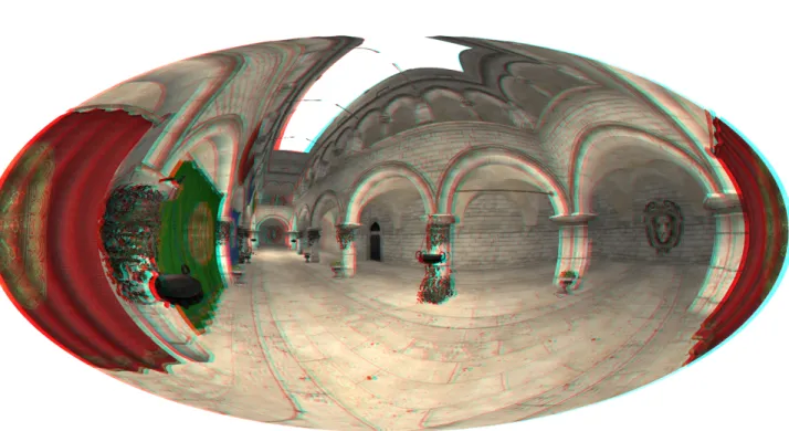
Figure 1: Stereoscopic rendering of a virtual environment covering a 360◦ horizontal field-of-view. The rendering is based on the Hammer projection which is classically used in cartography. Anaglyph image to be viewed with red/cyan glasses.
ABSTRACT
In this paper we introduce a novel approach for stereoscopic ren-dering of virtual environments with a wide Field-of-View (FoV)
up to 360◦. Handling such a wide FoV implies the use of
non-planar projections and generates specific problems such as for ras-terization and clipping of primitives. We propose a novel pre-clip stage specifically adapted to geometric approaches for which prob-lems occur with polygons spanning across the projection disconti-nuities. Our approach integrates seamlessly with immersive virtual reality systems as it is compatible with stereoscopy, head-tracking, and multi-surface projections. The benchmarking of our approach with different hardware setups could show that it is well compliant with real-time constraint, and capable of displaying a wide range of FoVs. Thus, our geometric approach could be used in various VR applications in which the user needs to extend the FoV and appre-hend more visual information.
Index Terms: H.5.2 [Information Interfaces and Presentation]:
User Interfaces—user-centered design; I.3.7 [Computer Graphics]: Three-Dimensional Graphics and Realism—Virtual Reality
∗e-mail: jerome.ardouin@esiea-ouest.fr †e-mail: {alecuyer,mmarchal,marchand}@irisa.fr
1 INTRODUCTION
Many virtual reality (VR) applications require a wide Field-of-View (FoV). A large FoV (i.e. up to 360 degrees) of virtual environments (VE) enables one to scan the surroundings and access visual infor-mation more rapidly. A panoramic FoV was even found to improve significantly the performance of users during a search and navi-gate task in desktop VE [2]. However, the rendering of wide FoV VE raises several critical issues [12]. Current approaches are ei-ther image-based or geometry-based [17], but often fail at being at the same time: stereo-compatible, GPU-friendly, and able to handle problems related to discontinuities of non-planar projections.
In this paper we propose a novel geometric method for the
stereoscopic rendering of VEs with large FoVs, i.e. above 120◦
and up to 360◦, as illustrated in Figure 1. Our method evaluates the
non-planar projection equation per vertex, and includes an innova-tive pre-clip stage in order to solve the problems occurring with polygons spanning across the projection discontinuities.
In the remainder of this paper, we first present related work in real-time rendering using non-planar projections. Then we describe step by step our novel approach to render wide FoV stereoscopic images in real-time. The results and overall performance of our method are reported and discussed in section 5. The paper ends with a general conclusion.
2 PREVIOUSWORK
Several studies concern omnidirectional views of real or virtual en-vironments. As an example, Ardouin et al. designed a device
to augment the human FoV to 360◦by processing images from a panoramic sensor [1]. In the VR field, projection-based immersive rooms or Head Mounted Displays (HMD) can immerse the user in a VE with often a large FoV. In almost all cases, visual information of the user’s surroundings is accessed sequentially. To do so, ei-ther a head tracker is considered to pan the view within an HMD or several planar screens are used to surround the user (CAVE) [6, 4]. An alternative to planar projection screens is curved surfaces [13] leading to wide screens with cylindrical or dome shape.
If a wide FoV visualization is required on a constrained sur-face, the rendering method has to rely on non-planar projections, mapping the space directions to the final viewport. The implemen-tation of non-planar projection should use either image-based or geometry-based rendering methods [17].
Images-based approaches render the scene six times with six perspective projections to off-screen textures that are often orga-nized as environment cube map. Then, the final view is rendered by addressing the textures with the desired non planar-projection equa-tions. There are various examples in the literature such as Van Oort-merssen’s FisheyeQuake and PanQuake [18]. Potential drawbacks of such approaches are sampling artifacts or hardware antialias-ing/anisotropic filtering incompatibility [9, 12]. Moreover, these methods are not able to generate coherent stereo pairs [15, 16].
Geometry-based approaches can be split into two groups. The first group considers an approximation of non-planar projection with several perspective projections (also known as Perspective Pieces Approximation or PPA). The second group computes the non-planar projection equation per vertex (called Per Vertex Projec-tion EvaluaProjec-tion or PVPE in the remainder of this paper). A classic process to perform PPA rendering is to render the scene geometry
ntimes according to the n perspective projections used to
approx-imate the desired non-planar projection. In [13] this approach is used to adapt single user stereoscopic displays to multi-user sce-nario. Implementations perform efficiently with a small number of projection pieces [3]. To alleviate saturation of vertex bandwidth when the number of pieces increases, Lorentz et al. proposed a 3-pass rendering method [9]. It replicates the rendered primitive on the GPU and determines which projection pieces the primitive is covering. This approach is characterized by an extensive use of geometry shaders but an alternative implementation using the tes-sellation unit of modern GPU can also be considered [9]. Stereo-scopic rendering can be achieved by rendering the scene two times, translating the projection center for each perspective piece accord-ing to the user’s eyes position. However, it still requires a large vertex processing bandwidth which can be a limitation. Alongside the processing pipeline remains difficult to implement on current graphic architectures.
PVPE methods could appear conceptually simpler to design. PVPE is compliant even with early programmable GPUs. Oros proposed a vertex shader implementation that is efficient for FoV
inferior to 180◦[11]. Alternatively, more complex projections can
be used. In [5], a flexible projection can model arbitrary curved viewing volumes. Moreover, the desired non-planar projection can be specifically computed to match spatial arrangement of display surfaces such as in [12]. However, in all cases, two limitations re-main. The first is the post-projection error on coarse geometry. The second limitation concern the rendering of primitives crossing a dis-continuity of the projection used [12]. These limitations are further discussed in section 3.1.
To the authors’ best knowledge, when considering the different techniques proposed so far in the field of virtual reality it seems that several issues and drawbacks pertain for real-time wide FoV rendering. Thus, in the next section, we propose a technique which remains compliant with projection discontinuity and stereoscopic rendering, scalable, relatively simple to implement (GPU-friendly) and efficient (real-time).
3 A NOVEL APPROACH FORSTEREOSCOPIC RENDERING
WITHNON-PLANARPROJECTION ANDWIDEFOV
To solve the technical challenges induced by wide FoV stereoscopic rendering, we propose a novel rendering pipeline that alleviates lim-itations of PVPE approaches. The successive steps of this pipeline are illustrated in Figure 2.
Tesselate Pre-Clip Project
Clip Raster Write Output (framebuffer)
Figure 2: Rendering pipeline proposed for wide FoV real-time ren-dering. Gray stages are implemented in shaders. The new pre-clip stage (dashed) represents our main contribution.
3.1 Limitations of current PVPE Methods
Per vertex evaluation of non-planar projection seems to be a com-pelling technique thanks to its compatibility with the standard ras-terization pipeline. From a technical point of view, a geometric PVPE approach for wide FoV rendering involves two main steps. First, the geometry is projected into the unit cube. For large FoV, a non-planar projection is mandatory. Second, the transformed prim-itives are rasterized through scan conversion, i.e. transformation of vectorial data to bitmaps. For performance reasons, the hardware accelerated rasterization pipeline has to be considered, alongside with its restrictions.
Then, the use of non-planar projection induces two major issues. First, the projection does not preserve shapes anymore, leading to important post-projection errors for geometry with low tessellation level. Second, the projection includes discontinuities: if a trian-gle spans across a discontinuity, it is not properly rasterized. For instance, if we consider a cylindrical equirectangular projection, a triangle spanning across the Oyz half-rear plane, represented by red and blue triangles in Figure 3, is rasterized improperly as shown in Figure 4. The vertices of the polygon are well transformed by the projection equation (their positions after transformation are co-herent), but the clipping stage of the standard pipeline is unable to detect and process such kind of polygon. Instead, the primitive is sent as is to the next stage and is rasterized across the viewport. To make up for this issue Petkov et al. [12] propose to simply not render a primitive spanning across a discontinuity of the projection. Alternatively, we propose to include a new clipping stage in the rendering pipeline. This will be presented in section 3.4.
3.2 Building a Projection Suitable for Wide FoV Real-Time Rendering
To be suitable for hardware-accelerated rasterization, a non-planar projection needs to remap the desired view volume to the unit cube. For x and y, the equirectangular projection described in equation (1) is a mapping among others that fits the requirements:
x = h2 f ovλ y = v2 f ovφ z = −1 + 2f ar−nearρ −near (1)
Where λ = arctan−ZX , φ = arcsinYρ and ρ =√X2+Y2+ Z2.
Several other projections can be applied [14]. With Hammer projection (Figure 1), the computation of x and y is more expensive
z y x O (1) (2) (3)
Figure 3: Issues when using an equirectangular projection. The pro-jection discontinuity is represented by the dashed line. Triangle (1) is compatible with standard rasterization. Triangles (2) and (3) generate issues at clipping and rasterization stages.
A B C A B C (a) (b) (c)
Figure 4: Rasterization issue for triangle projected across the dis-continuity of an equirectangular projection. (a): desired rendering in the final viewport. (b): the surface actually generated. (c): the prob-lem on a real scene: here, the triangles composing the red and blue drapes on the very right are rasterized across the whole viewport.
than with the equirectangular projection. When used, it leads to an ellipse shaped view. Note that there are various criteria to pre-fer or select a specific projection. The shape of the display surface can be considered [12] as well as the properties of the projection used [2]. Conformal projections preserve angles locally. Equidis-tant and equal-area projections preserve angular distances or sur-face area. This offers a wide range of possibilities in terms of visual rendering and final perception.
The amount of FoV covered by the final image can be controlled
through scalars vf ovand hf ov. The view volume rendered
corre-sponds to x and y coordinates in [−1, 1]. To cover the full FoV, one
can chose to use hf ov= 2π and vf ov= π. Finally, the Z coordinate
is generated as the distance from the projected point to the center of projection, also remapped to [−1, 1]. To do so, two clip distances are used to define clipping spheres instead of clipping planes used in the perspective case. The whole projection equation is then able to remap the spherical view volume to the unit cube as shown in Figure 5.
3.3 Tessellation of the Virtual Environment Geometry
PVPE approaches require a constraint on the tessellation of the input geometry. An overview of the requirements can be found
x z y
near clip sphere far clip sphere
x z y
P
Figure 5: Equirectangular projection used for rasterization. The map-ping to the unit cube exhibits discontinuities. Correspondence of sur-faces is highlighted with colors (blue, yellow and green). The small triangle (see left image) is cut in two parts. This illustrates the need for a new kind of clipping.
in [12]. Main guidelines are provided hereafter, in order to clarify its inclusion in our rendering pipeline as displayed in Figure 2.
A non-planar projection, such as equirectangular or Hammer projection is built to cover a wide FoV, but introduces distortions in the final view, transforming straight lines into curves, and poly-gons to curved surfaces. The curvature of the transformed primitive has to be approximated. The granularity of the geometry needs to ensure that the footprint of the primitive after projection is small enough to constrain the projection error. To do so, the geometry can be processed offline before the rendering or online with the tes-sellation feature available in modern GPU. Both processes can also be applied. Using a tessellation shader in this context offers the possibility, at each rendered frame, to control the way each poly-gon is subdivided. Primitives suffering from high distortion can be subdivided to a finer level whereas primitive in low distortion area of the projection can remain coarser. Such an approach is described in [12].
3.4 Our Novel "Pre-Clip" Stage
As illustrated in Figures 3, 4 and 5, when using a non-planar pro-jection, problems arise for triangles spanning across a discontinuity of the projection. The standard clipping algorithm is unable to de-tect and handle these particular cases. To be correctly rasterized, these triangles need to be specifically processed before applying the projection. For FoV smaller than 180 degrees the problem can be avoided by culling polygons behind the center of projection but current implementations targeting FoV above 180 degrees drop the rendering of this kind of triangles [12]. To keep the rendering of these triangles, an alternative solution is to clip them. Consider-ing an equirectangular projection, the additional clippConsider-ing step has to prevent situations in which a primitive is wrongly rasterized due to a span across the projection discontinuity. Focusing on triangle as input primitive, there are two configurations inducing problems (see Figure 3):
• Pole triangle: the triangle spans across the y axis;
• Rear triangle: the triangle spans across the rear half part of the Oyz plane.
Our novel approach consists in splitting the primitive in sub-parts that do not span across a discontinuity. The guideline for the algo-rithm is first to detect if a triangle needs to be clipped. If so, its edges are processed sequentially to detect if one crosses the dis-continuity. New vertices are generated on the discontinuity, and their attributes are computed using barycentric interpolation. If needed, the coordinates of the newly generated vertices are slightly corrected to guarantee that the vertex keeps a coherent position af-ter being projected. In the case of equirectangular projection, the
xcoordinate is forced to keep the same sign as the other vertices
composing the generated triangle, as illustrated in Figure 6. The algorithms 2 and 1 describe simplified versions of the algorithms implemented for the rear and pole triangles processing. For read-ability, it omits barycentric interpolation as well as small correction
Oyz plane Oyz plane O z x O z x Pole triangle clipping Rear triangle clipping
Figure 6: Clipping strategies for pole triangles, projected from top or bottom and spanning across Y axis, and rear triangles, projected from rear half-space and spanning across Oyz plane.
Algorithm 1 Pole Triangle Clipping
Input: A triangle T , vistands for the ith vertex
Output: A set OT of triangles ready to be projected with an equirectangular projection
if Oy intersects T then
I← computeIntersection(T, Oy)
id← 0 . Current ID in vertice list
for i ← 0, 2 do . Check each edge for split
V Lid← vi
id← id + 1
temp← OyzIntersect(vi, vi+1 mod 3)
if temp then
V Lid← temp
id← id + 1
end if end for
for i ← 0, 3 do . Store the 4 triangles
OTi← Triangle(I,V Li+1 mod id,V Li+2 mod id)
end for end if
of values introduced to avoid numerical computation errors. Fig-ure 7 illustrates the rendering, after equirectangular projection. The two types of clipping are highlighted: pole triangles are displayed with plain colors and rear triangles with soft gradient colors.
Our approach can comply with any non-planar projection. How-ever the pre-clip stage must be adapted to the discontinuities of the chosen projection. Nevertheless, one strategy for the pre-clip stage can fit for a whole family of projections. For example, the proce-dure detailed previously fits all cylindrical and pseudo-cylindrical projections [14] such as Hammer projection (Figure 1).
3.5 Computation of a Coherent Stereo Pair and Adapta-tion to Immersive Displays
To generate coherent images for left and right eyes, the warped vol-ume is considered as a regular object. Therefore, the rendering can rely on classical method used for real-time stereoscopic rendering. Two additional perspective projections are used. First, a zero par-allax plane is positioned at the desired distance in the unit cube. It defines the Z where stereoscopic disparity will be null (left and right images are merged). The two centers of projection are posi-tioned according to the desired inter-ocular distance. Near and far clipping planes are also required. They can be chosen to match the unit cube to optimize Z-buffer precision, but this is not mandatory. The final stereoscopic effect can be tuned through three parameters: the inter-ocular distance (iod), the user’s distance from the
projec-Algorithm 2 Rear Triangle Clipping
Input: A triangle T , vistands for the ith vertex
Output: A set OT of triangles ready to be projected with an equirectangular projection
if Oyz intersects T then
s0← OyzIntersect(v0, v1) . Compute v0v1edge / Oyz plane
intersection
s1← OyzIntersect(v1, v2)
s2← OyzIntersect(v2, v0)
if s0or s1or s2 then . An edge is crossing the Oyz plane
id← 0 . Current ID in vertice list
ns← −1 . Handle the non split edge id
for i ← 0, 2 do . Check each edge for split
V Lid← vi id← id + 1 if sithen V Lid= si id← id + 1 else ns← id end if end for
OT0← Triangle(V L(ns+1) mod id,V Lns+2 mod id,
V Lns+3 mod id)
OT1← Triangle(V Lns+3 mod id,V Lns+4 mod id,
V Lns+1 mod id)
OT2← Triangle(V Lns+1 mod id,V Lns+0 mod id,
V Lns+4 mod id) end if end if
Figure 7: VE rendered with equirectangular projection. The triangles processed and clipped in the pre-clip stage are highlighted with col-ors. At the bottom, pole triangles are rendered with solid colcol-ors. At the left and right borders, rear triangles that were clipped are ren-dered with soft colors.
tion plane (d) and the position of the zero-parallax plane in the unit cube (o f f set). After preliminary testings, we could set the values of these parameters to: iod = 0.5, d = 5 and o f f set = −0.8. Values are given in the normalized device coordinate frame.
There are various display systems that can be used to immerse a user in VEs: HMD, immersive rooms (e.g. CAVE), workbenches, or several other configurations of screens surrounding the user. The method we propose can be adapted to most of these setups. Adapt-ing our method to HMD mainly consists in integratAdapt-ing the data from a three degrees-of-freedom tracker (for head rotations). The data is used to modify the model-view matrix and has no influence on the projection used for the rendering. With immersive displays based on planar projection screens (CAVE, Wall, etc.) the data provided by a tracking system with six degrees-of-freedom needs to be in-tegrated. A straightforward method consists in considering the ge-ometry after the projection as a regular object, fitting the unit cube. This object can then be rendered with classical approach [6], where the tracking data control the center of projection of each perspective
(a) (b) (c)
Figure 8: Stereoscopic rendering using equirectangular projection and covering different FoV: (a) 120◦, (b) 180◦, (c) 360◦(Anaglyph images).
Figure 9: Stereoscopic rendering of the VE viewed from the top and using equirectangular projection (anaglyph image).
projection. Depending on the immersive display targeted, the unit cube may be scaled or translated to match the working area of the display. The method could also be used to target display systems with non-planar screens, such as domes or cylinders [3]. In these cases the non-planar projection should be chosen to match the phys-ical frame of the display. The final image could then be generated in one single pass.
4 IMPLEMENTATION OF THEPROPOSEDAPPROACH
Our approach was implemented in C++ language using OpenGL 4.2 and the GLSL shading language. The selected VE retained is the Sponza Atrium model [10]. The model was modified offline with a digital content creation tool to subdivide its geometry, of-floading the tessellation stage during real-time rendering. All the programmable stages of OpenGL 4.2 pipeline were required to im-plement the proposed pipeline (Figure 2).
From a sequential point of view, vertices are first transformed in the vertex shader, handling the model-view transformation. Vec-torial vertex attributes such as tangents, normals and bi-tangents are transformed with the inverse transpose model-view matrix as in regular rendering. The next step consists in refining the geometry (see details in section 3.3). With the pre-tessellated scene used, a constant level of additional tessellation in the tessellation control shader was found sufficient to limit the projection error. Alterna-tively, a more optimal algorithm as proposed in [12] could be used. In the next step, the assembled primitives are pre-clipped and pro-jected in the specially designed geometry shader. The pre-clipping algorithm presented in section 3.4 needs to access to the list of the vertices composing the primitive. Therefore, the geometry shader
is the designed place to implement this stage. The primitives are finally transformed with the desired non-planar projection (section 3.2). Concerning the fragment shader implementation, the Phong lightning equation is evaluated in eye space in order to keep the computation independent from the projection. However, deferred shading approach could be used if required [7].
Stereoscopy feature was implemented using two different tech-niques for image separation: anaglyph (color filter separation, ideal for compatibility and diffusion) and frame sequential (also known as active stereoscopy, for a better viewing experience). The two im-ages were rendered sequentially, in two different drawing passes. Alternatively, layered rendering could be implemented to process the scene only once per frame [17].
5 RESULTS ANDDISCUSSION
As a result, our method is able to perform real-time stereoscopic
rendering with FoVs up to 360◦. Figures 1, 8 and 9 illustrate
dif-ferent examples of stereoscopic images obtained. These images are rendered using anaglyph stereoscopy. Red/cyan glasses are re-quired for viewing. Figure 9 represents a top view of the Sponza Atrium VE. In this particular case, the understanding of the re-sulting view is not trivial. Distortions in the final rendering and the unusual point of view can mislead the viewer. The addition of stereoscopy seems to ease the perception of the structure and the ge-ometry of the VE. But future work would be necessary to formally assess the potential gain in perception.
The performance of our rendering pipeline was assessed using a standard graphics configuration and a single monitor screen. The test platform runs on Intel i3 2120, running at 3.3GHz, with 4GB
Table 1: Performance of our approach (framerates) as function of FoV, complexity of the VE to render, projection used and usage of anti-aliasing.
Type of Projection FoV(◦) Simple VE (fps) Complex VE (fps) Perspective 120 948 58 Equirectangular 120 488 42 Equirectangular 180 449 40 Equirectangular 270 446 40 Equirectangular 360 459 42 Equirectangular with CSAA32x 360 396 36 Hammer 360 476 38 Hammer with CSAA32x 360 470 39
RAM, and an NVidia GeForce 560 GTX graphic board. Vertical synchronization was disabled. Stereoscopy was disabled (multi-plying the final performance by nearly two). Rendered viewport was sized 1024 × 512 pixels. Two different projections were tested: equirectangular and Hammer. Two VEs with different complexities were used for the benchmark: the Sponza Atrium [10] as a com-plex pre-tessellated VE (225839 triangles), and a cornell-box scene as a simple VE (34 triangles). Table 1 displays the resulting framer-ates, for both VEs, depending on the different FoVs and projections used.
Perspective projection was implemented conserving the pipeline presented in section 3, maintaining all the stages but bypassing the pre-clip stage which is no longer necessary. The results for perspec-tive projection and the equirectangular projection give an estimation of the pre-clip stage impact on framerate. Interestingly enough, sev-eral cutting-edge hardware improvements such as antialiasing could be incorporated with small processing-time costs. As an example, hardware antialiasing (CSAA 32x) has been introduced and tested with no visible impact on framerate. Moreover, the FoV extension seems to not influence the rendering performance. In fact, the FoV tuning is available through the mapping to the unit cube (Equa-tion (1)). The main processing duty and the main bottlenecks seem related to the geometry processing steps (clipping and projection) which are implemented in the geometry shader. As our implemen-tation does not feature optimization such as frustum culling, all the geometry is processed whatever the FoV used. So setting a smaller FoV does not imply an augmentation of performances. The frag-ment processing is here a quite simple standard per-pixel Phong shading that does not seem to impair the final performance.
From the user side, a limitation could be observed concerning the perception of the rendered environments. The human FoV is physi-ologically limited. Providing more FoV in a view can be viewed as a remapping of a wide FoV to a smaller one, fitting the human natu-ral FoV. This induces a down-scaling of the VE observed. Thus, the perception of scales could become biased, even when using an im-mersive display. Alongside with the scale perception, perception of depth could be also impaired. However as it can be deduced from section 3.2, the function used to remap the z coordinates can be tuned. This represents a field of investigation to maximize the qual-ity of the final depth and stereoscopic effects. A limitation could be the accuracy of the resulting image in areas of high distortion. Arti-facts can be seen in Figure 7 and 8.c: the curvature of the pavement is not regular. Rasterization and interpolation of vertex attributes in-troduce this bias by using linear interpolation. There are two ways to improve this shortcoming. One way is to augment the tessella-tion of the VE. In this case, a trade-off between performance and image quality has to be done. Another solution consists in perform-ing rasterization of curved primitives. Such methods exists [8] but are difficult to make efficient (need to enclose the primitive in a
bounding shape, discard a lot of fragments...). Future evolution of hardware could make such approaches more usable by bringing the rasterization stage programmable.
6 CONCLUSION
In this paper, we proposed a novel geometry-based approach for stereoscopic rendering of VEs with a wide field of view. Our ap-proach includes an innovative pre-clip stage to solve problems oc-curring with polygons spanning across the projection discontinu-ities. The rendering pipeline complies with current hardware archi-tectures and non-planar projections such as the projections classi-cally used in cartography. Our method has been extended to han-dle the computation of stereoscopic images and the use of immer-sive VR systems. The benchmarking of our approach with standard desktop computers and graphics cards could show that it success-fully meets real-time performance, and that it is capable of
display-ing a wide range of FoVs, up to 360◦. Therefore, our novel
ap-proach could be used in various VR applications in which the user needs to apprehend more visual information, with an extended FoV.
REFERENCES
[1] J. Ardouin, A. Lécuyer, M. Marchal, C. Riant, and E. Marchand. "Fly-VIZ": A Novel Display Device to Provide Humans with 360◦Vision by Coupling Catadioptric Camera with HMD. In Proc. of VRST, pages 41–44, 2012.
[2] J. Ardouin, A. Lécuyer, M. Marchal, and E. Marchand. Navigating in Virtual Environments with 360◦Omnidirectional Rendering. In Proc. of IEEE 3DUI, pages 95–98, 2013.
[3] P. Bourke. Synthetic stereoscopic panoramic images. In Interactive Technologies and Sociotechnical Systems, Lecture Notes in Computer Science. Springer, 2006.
[4] D. A. Bowman, E. Kruijff, J. J. LaViola, and I. Poupyrev. 3D User In-terfaces: Theory and Practice. Addison Wesley Longman Publishing Co., Inc., 2004.
[5] J. Brosz, F. F. Samavati, M. S. T. Carpendale, and M. C. Sousa. Single camera flexible projection. In Proc. of NPAR, pages 33–42, 2007. [6] C. Cruz-Neira, D. J. Sandin, and T. A. DeFanti. Surround-screen
projection-based virtual reality: the design and implementation of the cave. In Proc. of SIGGRAPH, pages 135–142, 1993.
[7] M. Deering, S. Winner, B. Schediwy, C. Duffy, and N. Hunt. The triangle processor and normal vector shader: a vlsi system for high performance graphics. In Proc. of SIGGRAPH, pages 21–30, 1988. [8] J.-D. Gascuel, N. Holzschuch, G. Fournier, and B. Péroche. Fast
non-linear projections using graphics hardware. In Proc. of I3D, pages 107–114, 2008.
[9] H. Lorenz and J. Döllner. Real-time piecewise perspective projections. In Proc. of GRAPP, pages 147–155, 2009.
[10] F. Meinl. Sponza model. http://www.crytek.com.
[11] D. Oros. A conceptual and practical look into spherical curvilinear projection. www.frost-art.com.
[12] K. Petkov, C. Papadopoulos, M. Zhang, A. E. Kaufman, and X. Gu. Interactive visibility retargeting in vr using conformal visualization. IEEE TVCG, 18(7):1027–1040, 2012.
[13] A. Simon, R. Smith, and R. Pawlicki. Omnistereo for panoramic vir-tual environment display systems. In Proc. of IEEE VR, 2004. [14] J. Snyder. Flattening the Earth: Two Thousand Years of Map
Projec-tions. University of Chicago Press, 1997.
[15] M. Trapp and J. Döllner. Generalization of single-center projections using projection tile screens. In Computer Vision and Computer Graphics. Theory and Applications, volume 24 of Communications in Computer and Information Science. Springer, 2009.
[16] M. Trapp and J. Döllner. A generalization approach for 3d viewing deformations of single-center projections. In Proc. of GRAPP, pages 162–170, 2008.
[17] M. Trapp, H. Lorenz, and J. Döllner. Interactive stereo rendering for non-planar projections of 3d virtual environments. In Proc. of GRAPP, pages 199–204, 2009.
[18] W. van Oortmerssen. Fisheyequake. http://strlen.com/gfxengine/ fisheyequake/.