TOWARDS SUSTAINABLE ELECTROCHEMICAL ACIDIFICATION OF KRAFT BLACK LIQUOR FOR LIGNIN EXTRACTION: PROOF OF CONCEPT, CONTROL
OF MEMBRANE FOULING AND YIELD ENHANCEMENT
MARYAM HADDAD
D´EPARTEMENT DE G´ENIE CHIMIQUE ´
ECOLE POLYTECHNIQUE DE MONTR´EAL
TH`ESE PR´ESENT´EE EN VUE DE L’OBTENTION DU DIPL ˆOME DE PHILOSOPHIÆ DOCTOR
(G´ENIE CHIMIQUE) JUIN 2016
c
´
ECOLE POLYTECHNIQUE DE MONTR´EAL
Cette th`ese intitul´ee :
TOWARDS SUSTAINABLE ELECTROCHEMICAL ACIDIFICATION OF KRAFT BLACK LIQUOR FOR LIGNIN EXTRACTION: PROOF OF CONCEPT, CONTROL
OF MEMBRANE FOULING AND YIELD ENHANCEMENT
pr´esent´ee par : HADDAD Maryam
en vue de l’obtention du diplˆome de : Philosophiæ Doctor a ´et´e dˆument accept´ee par le jury d’examen constitu´e de :
M. PATIENCE Gregory S., Ph. D., pr´esident
M. PARIS Jean, Ph. D., membre et directeur de recherche
M. SAVADOGO Oumarou, D. d’´etat, membre et codirecteur de recherche M. BAZINET Laurent, Ph. D., membre et codirecteur de recherche M. LEGROS Robert, Ph. D., membre
DEDICATION
ACKNOWLEDGEMENTS
This is the end of my PhD study which would not have been rewarding without the people who supported and inspired me. I would like to take this opportunity to express my gratitude to some of them.
First and for most, I would like to thank my supervisor co-supervisors for their encourage-ment, inspirational ideas, extensive support and patience during my PhD project. It was a great honor to work under your supervisions. Prof. Paris, thank you for believing in me from the beginning on. You are an inspiration of hard work and determination. Prof. Savadogo, I am grateful for your constructive suggestions and advice that helped me to see my project from the fundamental point of view and be a better researcher. Prof. Bazinet, I am immen-sely grateful for the privilege of working under your supervision and learning from you. Your constant support, motivation and guides were invaluable to me during my PhD study and your motivation and dedication to the scientific work is always an inspiration for me.
I extend my gratitude to Mrs. Beaudry, Mr. Cloutier and Mr. Labreque at Hydro-Qu´ebec for their help, productive comments and contribution to this project especially at the beginning of my PhD journey.
A special word of thanks goes to Prof. Perrier and Dr. Marinova for their constructive advice and motivations during my stay at E2D2BF group. Also, I take this opportunity to sincerely
thank Dr. Mikhaylin for his fruitful contribution to this research and being the co-author of two publications.
Special thanks to the technical staff of the chemical engineering department, especially Mr. Pilon, Mr. Delisle, Mr. Robin, Mrs. Rousseau and Mrs. Mbelu for their help and technical support.
I would like to thank the students and interns who contributed to this research and also all of my colleagues for the fun time over the lunch breaks and potlucks. Francois thank you very much for translating the abstract. Moreover, my heartfelt thanks to my dearest friends. Thanks for your sincere friendship, support, encouragements and for making my life colorful. Finally, I would like to thank my life, my family. Words are powerless to express my deepest gratitude for your everlasting and unconditional love, your support regardless of distance, your generosity and enormous patience. I would have not made it this far without you. Maman, Baba, Mahmoud and Elmira, thanks for always being there for me, respecting me and inspiring me. Love you all.
R´ESUM´E
La baisse de la demande en produits traditionnels issus des pˆates et papiers, la concurrence des ´economies ´emergentes, les fluctuations du prix du p´etrole et les moyens d’incitations envers les produits verts ont pouss´e l’industrie des pˆates et papiers (P & P) `a d´evelopper de nouveaux produits issus des composants du bois. La transformation de cette industrie, plus particuli`erement des usines Kraft, en bioraffineries foresti`eres int´egr´ees (IFBR) est consid´er´ee comme une alternative efficace en vue d’augmenter les revenus des usines et de diversifier de fa¸con durable leur portefeuille de produits.
Le proc´ed´e Kraft est la technique de production de pˆates et papier la plus r´epandue au monde. Dans la plupart de ces usines, environ 50% des composants du bois (pour la plupart les h´emicelluloses et la lignine) sont dissouts dans un courant r´esiduel appel´e liqueur noire (LN) et sont brˆul´es dans la chaudi`ere de l’usine afin de produire de la vapeur, de l’´electricit´e et de r´eg´en´erer les produits chimiques utilis´es dans le proc´ed´e. Par convention, lorsqu’une bioraffinerie foresti`ere est int´egr´ee `a une usine, les composants du bois sont s´epar´es du courant de pˆate et sont transform´es en produits biosourc´es `a valeur ajout´ee. Plus pr´ecis´ement, la lignine extraite peut ˆetre utilis´ee comme biocarburant ou comme pr´ecurseur `a une vaste gamme de d´eriv´es ph´enoliques. De plus, l’extraction de la lignine peut augmenter la capacit´e de l’usine Kraft en faisant diminuer la charge de sa chaudi`ere.
Ce doctorat fait partie d’un projet d’´etude plus large ´evaluant le potentiel de l’impl´ementation d’une bioraffinerie traitant la lignine dans des usines Kraft existante afin d’augmenter leurs revenus, diversifier leur portefeuille, et les rendre durables sur le long terme. Par cons´equent, l’objectif principal de cette th`ese ´etait d’identifier, de concevoir et de d´evelopper une m´ethode efficace et ´ecologique d’acidification de la liqueur noire pour l’extraction de la lignine (qui peut ˆ
etre une alternative int´eressante `a la technique d’extraction par acidification) et finalement de l’int´egrer dans une usine Kraft existante. L’acidification ´electrochimique de la LN Kraft par ´electrodialyse avec membrane bipolaire (EDBM) a ´et´e s´electionn´ee en ce sens comme une voie technologique prometteuse et durable. L’objectif principal de ce projet de recherche a ´et´e de valider le concept, d’´eliminer les d´efauts du proc´ed´e, et d’en am´eliorer les performances afin de le rendre r´ealisable `a grande ´echelle.
La premi`ere ´etape de cette recherche pionni`ere a ´et´e de mener une ´etude de faisabilit´e tech-nique afin de d´eterminer les avantages et les limites de la m´ethode d’acidification ´electrochimi. Les r´esultats en d´ecoulant ont indiqu´e que l’acidification de la LN par la technique d’EDBM requiert une consommation significativement moindre en produits chimiques par-rapport
`
a l’acidification par voie chimique. Cependant, l’encrassement de la membrane ´echangeuse d’ions (IEM) en affecte d´efavorablement les performances. Nous avons trouv´e que la protona-tion des groupes acides de la lignine r´esulte en une formation de lignine collo¨ıdale d´estabilis´ee puis en amas de lignine sur la surface des IEM.
L’objectif de la seconde phase ´etait d’´eliminer l’encrassamrnt de la membrane, d’am´eliorer la performance du proc´ed´e au moyen d’une s´election des IEM les plus fiables disponibles `a l’´echelle commerciale, et d’am´eliorer les conditions op´eratoires du proc´ed´e d’EDBM. Les r´esultats exp´erimentaux ont mis en ´evidence que changer le type d’IEM ne permet pas d’att´enuer le ph´enom`ene d’encrassement et qu’un cycle de nettoyage chimique ´etait n´ecessaire. De plus, il fut d´emontr´e que la composition chimique de la LN ainsi que la temp´erature d’op´eration et les param`etres hydrodynamiques peuvent substantiellement am´eliorer l’effica-cit´e et la consommation en ´energie du syst`eme d’EDBM tout en retardant l’encrassement des IEM.
La phase finale mit l’emphase sur l’am´elioration du rendement en intensifiant le proc´ed´e d’acidification ´electrochimi. La mise en place d’une ´etape de nettoyage en ligne au moyen d’un champ ´electrique puls´e pourrait supprimer l’encrassement de la membrane, intensifier l’´etape d’acidification et augmenter l’efficacit´e du proc´ed´e jusqu’`a 80%.
Sur la base des r´esultats prometteurs pr´esent´es dans cette th`ese, nous avons conclu que l’appli-cation du proc´ed´e d’acidification ´electrochimi par d’EDBM a r´eduit de mani`ere substantielle la consommation en produits chimiques et la g´en´eration d’effluents. De plus, la production in situ de coproduits pouvant ˆetre valoris´es, tels que la soude caustique, peuvent faire du proc´ed´e d’EDBM une op´eration unitaire ´ecologique et rentable au sein d’une bioraffinerie foresti`ere int´egr´ee `a une usine.
ABSTRACT
Decreasing demand of traditional pulp and paper products, competition from emerging economies and oil price volatility as well as incentives for green products encouraged the pulp and paper industry to look for novel products made from wood components. Transfor-mation of the pulp and paper industry and particularly Kraft pulping mills into integrated forest biorefinery (IFBR) is considered as an effective alternative to increase the revenue of the mills and substantially diversify their product portfolio.
Kraft process is the dominant pulp and paper production method worldwide. In most of the conventional Kraft pulping mills around 50% of the wood components (mainly hemicel-lulose and lignin) are dissolved in a residual stream called black liquor (BL) and combusted in the recovery boiler to produce steam, electricity and re-generate the cooking chemicals. By contrast, in an IFBR plant wood constituents are separated from the pulp stream and transformed into value-added bio-based products. In particular, extracted lignin can be used as biofuels or as a precursor to a vast phenolic platform of chemical pathways. Furthermore, lignin extraction can increase the capacity of the Kraft mill by decreasing the load of its recovery boiler.
This PhD project was part of a broader research study which evaluates the possibility of lignin biorefinery implementation in existing Kraft pulping mills to improve their revenue, diversify their portfolio and make them sustainable in the long term. Therefore, the main objective of this thesis was to identify, design and develop an efficient and eco-friendly BL acidification method for lignin extraction which can be an attractive alternative to the chem-ical acidification technique and eventually integrated into an existing Kraft pulping mill. To this end, electrochemical acidification of the Kraft BL via electrodialysis with bipolar mem-brane (EDBM) was selected as a promising and sustainable pathway. The main focus of this research was to validate the concept, eliminate the process drawbacks and enhance the performance of the EDBM process in order to make it practically feasible for a large scale implementation.
As the first step for conducting this pioneering research, a technical feasibility study was carried out to address the advantages and limitations of the electrochemical acidification method. The results of this feasibility study indicated that the acidification of the Kraft BL via the EDBM technique required a significantly less chemicals versus the chemical acidifi-cation approach. However, fouling of the ion exchange membranes (IEM) adversely affected its performance. It was found that the protonation of the lignin phenolic groups resulted
in formation of destabilized colloidal lignin and eventually produced lignin clusters on the surface of the IEMs.
The focus of the second phase was to eliminate the membrane fouling and enhance the performance of the process by means of screening the most reliable and commercially available IEMs as well as improving the operational conditions of the EDBM process. The experimental results implied that changing the type of the IEMs could not mitigate the fouling phenomenon and a chemical cleaning cycle was inevitable. In addition, it was demonstrated that BL chemical composition as well as operational temperature and hydrodynamics parameters could substantially improve the current efficiency and energy consumption of the EDBM system and postpone the fouling of the IEMs.
Yield enhancement by intensifying the electrochemical acidification process was the main intention of the final phase. Implementation of an in-line cleaning step by means of pulsed electric field application could successfully suppress the membrane fouling, intensify the acid-ification step and enhance the process efficiency up to 80%.
On the basis of the promising results presented in this thesis, it was concluded that application of the electrochemical acidification process via the EDBM method substantially reduced the chemical consumption and effluent generation. Furthermore, an in situ production of a valuable side product i.e. caustic soda can make the EDBM process an eco-efficient and profitable operational unit inside the IFBR plant.
TABLE OF CONTENTS DEDICATION . . . iii ACKNOWLEDGEMENTS . . . iv R´ESUM´E . . . v ABSTRACT . . . vii TABLE OF CONTENTS . . . ix
LIST OF TABLES . . . xiii
LIST OF FIGURES . . . xv
ACRONYMS . . . xix
CHAPTER 1 INTRODUCTION . . . 1
CHAPTER 2 LITERATURE REVIEW . . . 5
2.1 Ion Exchange Membrane (IEM ) . . . 5
2.2 Electro-Membrane Processes Used for Electrochemical Acidification . . . 7
2.2.1 Membrane Electrolysis (EL) . . . . 7
2.2.2 Conventional Elctrodialysis (ED) . . . . 8
2.2.3 Elctrodialysis with Bipolar Membrane (EDBM ) . . . . 11
2.3 Critical Literature Review . . . 13
2.3.1 Electrolysis of Black Liquor . . . 13
2.3.2 Electrodialysis of Black Liquor . . . 15
2.3.3 Electrodialysis of Black Liquor using Bipolar Membrane . . . 16
CHAPTER 3 OBJECTIVES AND METHODOLOGY . . . 17
3.1 Main Objective . . . 17
3.2 Methodology . . . 17
3.3 Presentation of Publications . . . 19 CHAPTER 4 ARTICLE 1 : A FEASIBILITY STUDY OF A NOVEL
EXTRACT LIGNIN . . . 21
4.1 Introduction . . . 21
4.2 Theoretical Background . . . 25
4.2.1 Principle of Electrodialysis by Bipolar Membrane to Acidify Kraft Black Liquor . . . 25
4.2.2 Lignin Precipitation Yield . . . 26
4.3 Experimental . . . 26
4.3.1 Membranes and Materials . . . 26
4.3.2 Methods . . . 27
4.3.3 Protocol . . . 28
4.3.4 Analyses . . . 29
4.4 Results and Discussion . . . 30
4.4.1 Black Liquor Electrical Conductivity . . . 30
4.4.2 Electrochemical Acidification of Kraft Black Liquor . . . 31
4.4.3 Comparison of Electrochemical Acidification and Chemical Acidifica-tion Methods . . . 34
4.5 Conclusion . . . 37
CHAPTER 5 ARTICLE 2 : FOULING IDENTIFICATION OF ION-EXCHANGE MEM-BRANES DURING ACIDIFICATION OF KRAFT BLACK LIQUOR BY ELEC-TRODIALYSIS WITH BIPOLAR MEMBRANE . . . 38
5.1 Introduction . . . 38
5.2 Experimental . . . 40
5.2.1 Membranes and Materials . . . 40
5.2.2 Electrochemical acidification Apparatus and Protocol . . . 41
5.2.3 Analysis Methods . . . 42
5.3 Results and Discussion . . . 44
5.3.1 Global System Resistance . . . 44
5.3.2 Black Liquor Analysis . . . 45
5.3.3 Membrane Thickness and Ash Content . . . 46
5.3.4 Electron Microscopy and Elemental Analysis . . . 46
5.3.5 X-ray Photoelectron Spectrometry (XP S) Analysis . . . . 48
5.3.6 Proposed Fouling Mechanisms . . . 50
5.4 Conclusion . . . 53 CHAPTER 6 ARTICLE 3 : ELECTROCHEMICAL ACIDIFICATION OF KRAFT
ION EXCHANGE MEMBRANE INTEGRITY . . . 54
6.1 Introduction . . . 55
6.2 Experimental . . . 57
6.2.1 Membranes and Materials . . . 57
6.2.2 Electrochemical Acidification Set-up . . . 58
6.2.3 Protocol . . . 59
6.2.4 Global System Resistance . . . 60
6.2.5 Membrane Properties . . . 61
6.3 Results and Discussion . . . 63
6.3.1 Global System Resistance . . . 63
6.3.2 Membrane Properties . . . 63
6.3.3 Chemical Cleaning Mechanisms . . . 70
6.4 Conclusion . . . 73
CHAPTER 7 ARTICLE 4 : EFFECT OF PROCESS VARIABLES ON THE PER-FORMANCE OF ELECTROCHEMICAL ACIDIFICATION OF KRAFT BLACK LIQUOR BY ELECTRODIALYSIS WITH BIPOLAR MEMBRANE . . . 74
7.1 Introduction . . . 75
7.2 Experimental . . . 78
7.2.1 Membranes and Materials . . . 78
7.2.2 Electrochemical Acidification Apparatus and Protocol . . . 78
7.2.3 Design of Experiments . . . 81
7.2.4 Analysis and Process Evaluation . . . 81
7.3 Results and Discussion . . . 83
7.3.1 Black Liquor Dynamic Viscosity . . . 83
7.3.2 Black Liquor Electrical Conductivity . . . 84
7.3.3 Influence of Process Variables on Electrodialytic Parameters . . . 85
7.3.4 Influence of Process Variables on System Hydrodynamics (Reynolds Number) . . . 91
7.3.5 Evolution of System Performance . . . 93
7.4 Conclusion . . . 95
CHAPTER 8 ARTICLE 5 : ELECTROCHEMICAL ACIDIFICATION OF KRAFT BLACK LIQUOR : IMPACTS OF PULSED ELECTRIC FIELD APPLICATION ON BIPOLAR MEMBRANE COLLOIDAL FOULING AND PROCESS INTENSI-FICATION . . . 98
8.2 Experimental . . . 100
8.2.1 Membranes and Materials . . . 100
8.2.2 Electrochemical Acidification Set-up . . . 101
8.2.3 Protocol . . . 102
8.2.4 Membrane Analyses . . . 104
8.2.5 Process Evaluation . . . 105
8.3 Results and Discussion . . . 106
8.3.1 Membrane Analysis . . . 106
8.3.2 Evolution of Electrodialytic Parameters . . . 109
8.3.3 Evolution of System Performance . . . 116
8.3.4 Proposed Pulsed Electric Field Mechanisms . . . 119
8.4 Conclusion . . . 122
CHAPTER 9 BLACK LIQUOR ACIDIFICATION FOR LIGNIN EXTRACTION : A PRELIMINARY COMPARISON BETWEEN CHEMICAL AND ELECTROCHEMI-CAL ACIDIFICATION PATHWAYS . . . 126
9.1 Introduction . . . 126
9.2 Experimental . . . 126
9.2.1 Membranes and Materials . . . 126
9.2.2 Chemical Acidification Apparatus and Protocol . . . 127
9.2.3 Electrochemical Acidification Apparatus and Protocol . . . 128
9.2.4 Analyses . . . 128
9.3 Results and Discussion . . . 130
9.3.1 Comparison of Electrochemical Acidification and Chemical Acidifica-tion Methods . . . 130
9.3.2 Lignin Impurities . . . 131
9.4 Conclusion and Perspectives . . . 132
CHAPTER 10 GENERAL DISCUSSION . . . 133
CHAPTER 11 CONCLUSIONS, ORIGINAL CONTRIBUTIONS AND RECOMMEN-DATIONS . . . 138
11.1 Conclusions . . . 138
11.2 Original Contributions . . . 139
11.3 Recommendations . . . 139
LIST OF TABLES
Table 1.1 : Three main technologies for lignin extraction from black liquor . . . . 3 Table 2.1 : Applied methods for controlling and minimizing the fouling of the IEM s
during the electromembrane processes [38] . . . 10 Table 4.1 : Ion exchange membranes specifications provided by their supplier . . . 27 Table 4.2 : Applied operational conditions during electrochemical acidification
me-thod . . . 29 Table 4.3 : Characteristics of Kraft Black Liquor . . . 30 Table 5.1 : Ion exchange membranes specifications provided by their supplier . . . 40 Table 5.2 : Applied operational conditions during electrochemical acidification method 41 Table 5.3 : XP S Operational Conditions . . . . 44 Table 5.4 : Characteristics of Kraft Black Liquor . . . 45 Table 5.5 : Membrane Thickness and Ash Content . . . 46 Table 5.6 : Identification of main chemical bonding from high resolution XP S scan 49 Table 6.1 : Characteristics of Kraft Black Liquor . . . 58 Table 6.2 : Applied Operational Conditions during Electrochemical Acidification of
the Kraft Black Liquor . . . 58 Table 6.3 : Membrane Thickness (mm) . . . . 64 Table 6.4 : Contact Angle measurements (◦) . . . 68 Table 6.5 : Ion Exchange Capacity of Cation Exchange Membranes (meq. g−1) . . 69 Table 6.6 : Membrane Electrical Resistance (Ω cm2) . . . 70 Table 7.1 : Ion exchange membranes specifications provided by their suppliers . . 78 Table 7.2 : Main specifications of the EDBM stack . . . . 79 Table 7.3 : Applied Operational Conditions during Electrochemical Acidification of
the Kraft BL . . . . 81 Table 7.4 : Characteristics of Kraft BL solutions . . . . 86 Table 7.5 : Parameters of the BL electrical conductivity fitting equations . . . . . 96 Table 7.6 : Parameters of the N aOH electrical conductivity fitting equations . . 97 Table 7.7 : Parameters of the BL pH fitting equations . . . 97 Table 8.1 : Ion exchange membranes specifications provided by their suppliers . . 100 Table 8.2 : Characteristics of Kraft Black Liquor . . . 101 Table 8.3 : Applied Operating Conditions during Electrochemical Acidification of
the Kraft Black Liquor . . . 104 Table 8.4 : Membrane Thickness (mm) . . . . 107
Table 8.5 : Parameters of the BL electrical conductivity fitting equations . . . . . 123 Table 8.6 : Parameters of the N aOH electrical conductivity fitting equations . . 124 Table 8.7 : Parameters of the BL pH fitting equations . . . 124 Table 8.8 : Parameters of the BL sodium concentration fitting equations . . . . . 125 Table 8.9 : Parameters of the BL lignin content fitting equations . . . 125 Table 9.1 : Ion exchange membranes specifications provided by their suppliers . . 127 Table 9.2 : Characteristics of Kraft Black Liquor . . . 129 Table 9.3 : Acidification parameters obtained from electrochemical and chemical
acidification steps . . . 130 Table 9.4 : Lignin ash content and consumed acid during the washing steps . . . . 131
LIST OF FIGURES
Figure 1.1 : Forest industry production trend in Canada [1] . . . 1
Figure 1.2 : A schematic drawing of a conventional Kraft pulping process . . . 2
Figure 2.1 : A cationic exchange membrane (CEM ) with fixed carboxylic acid charges 5 Figure 2.2 : The structure of a Bipolar Membrane (BP M ) . . . . 7
Figure 2.3 : A simple membrane electrolysis (EL) cell . . . . 8
Figure 2.4A flow-diagram of a conventional ED stack . . . . 9
Figure 2.5 : A schematic representation of the EDBM process . . . . 11
Figure 2.6 : Two-compartments EDBM cell arrangement for production of (a) base and (b) acid from their corresponding salts . . . 12
Figure 2.7 : Membrane permselectivity failure that can affect the EDBM perfor-mance [39] . . . 13
Figure 2.8 : Basic operation of the BL electrolysis acidification process . . . . 14
Figure 2.9 : Electrodialysis of black liquor in three compartment arrangement . . 15
Figure 2.10 : The BL recaustization steps performed by Koumoundouros et al. [46] 16 Figure 3.1 : A representation of overall methodology phases . . . 18
Figure 4.1 : A simplified illustration of the Kraft pulping process . . . 23
Figure 4.2 : Basic operation of the BL electrolysis (CEM : Cation exchange mem-brane) . . . 24
Figure 4.3 : Principle of electrodialysis with bipolar membrane (EDBM ) for the acidification of Kraft BL (BP M : bipolar membrane and CEM : cation ex-change membrane) . . . 26
Figure 4.4 : Schematic diagram of the electrochemical acidification process . . . . 28
Figure 4.5 : Evolution of the Kraft BL electrical electrical conductivity as a function of temperature and T DS content of the BL . . . . 31
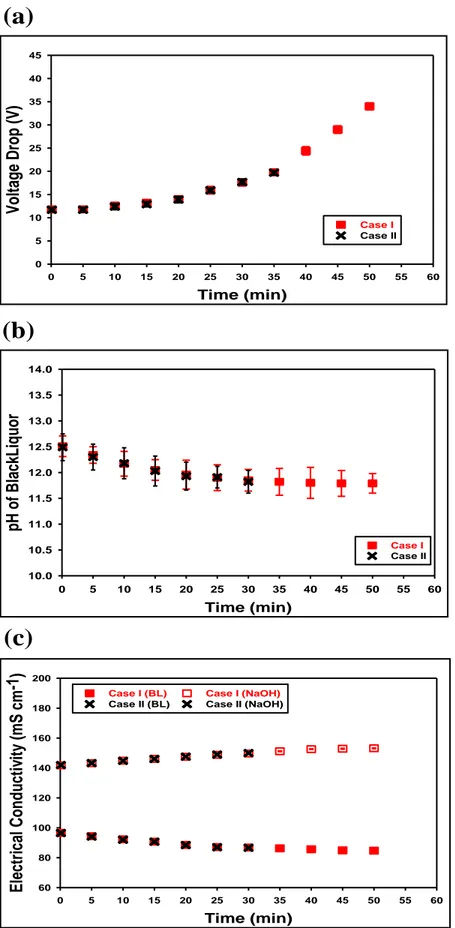
Figure 4.6 : (a) Voltage drop, (b) pH evolution of BL and (c) electrical conductivity profiles of BL and N aOH during electrochemical acididification of Kraft BL 33 Figure 4.7 : Formed deposit layer on the surface and in the space between the ion exchange membranes inside BL compartment during the electrochemical acidification of the Kraft BL (a) : case I (the electrochemical acidification was terminated when the voltage limit of the DC power supply was reached) (b) : case II (the electrochemical acidification was stopped when the voltage drop started to increase rapidly) . . . 34
Figure 4.8 : (a) Filtration rate, (b) lignin precipitation yield and (c) acid consump-tion of electrochemical and chemical acidificaconsump-tion methods . . . 36 Figure 5.1 : A simplified representation of the Kraft pulping process . . . 39 Figure 5.2 : Schematic diagram of the electrochemical acidification apparatus and
the EDBM cell . . . . 42 Figure 5.3 : Global system resistance during the electrochemical acidification of the
Kraft BL via EDBM method . . . 45 Figure 5.4 : Scanning electron microscopy (SEM ) images and elemental analysis
(EDX) of (a) the fresh and the used CEM in contact with : (b) black liquor and (c) caustic soda solutions . . . 47 Figure 5.5 : Scanning electron microscopy (SEM ) and elemental analysis (EDX)
of (a) the fresh and (b) the used cation exchange layer as well as (c) the fresh and (d) the used anion exchange layer of the BP M . . . . 48 Figure 5.6 : XP S survey spectra of (a) fouled CEM and (b) fouled BP M (KLL
peaks represent the auger peeks) . . . 50 Figure 5.7 : Fouling mechanism on the surface of the IEM s during the EDBM
pro-cess ((a) : Protons production and lignin protonation, (b) : Lignin nucleation phenomenon on the surface of the BP M , (c) : Formation of lignin clusters on the surface of the BP M ,(d) : Precipitation of the lignin in the space between the BP M and CEM and interruption of the lignin aggregation on the surface of the CEM due to the hydroxide ions leakage through the CEM ) . . . 52 Figure 6.1 : A schematic illustration of Kraft process . . . 55 Figure 6.2 : Electrodialysis with bipolar membrane (EDBM ) stack (BP M : bipolar
membrane and CEM : cation- exchange membrane) . . . . 59 Figure 6.3 : Schematic diagram of the electrochemical acidification set-up . . . 59 Figure 6.4 : Global system resistance during the EDBM process with different
cation exchange membranes . . . 63 Figure 6.5 : Scanning electron microscopy (SEM ) and elemental analysis (EDX)
of the (a) fresh and (b) fouled ion exchange membranes in contact with the BL solution . . . . 65 Figure 6.6 : Scanning electron microscopy (SEM ) and elemental analysis (EDX)
of the cleaned ion exchange membranes with (a) caustic soda solution and (b) fresh diluted black liquor solution (F BM : bipolar membrane, FuMA-Tech, F KB : cation exchange membrane, FuMA-FuMA-Tech, CM B : cation exchange membrane, Neosepta, CM (H) − P ES : cation exchange membrane, Mega a.s., Nafion 324 : cation exchange membrane, DuPont) . . . 66
Figure 6.7 : SEM images of the deposit lignin on the surface of the fouled BP M at (a) 2000 X and (b) 5000 X . . . . 71 Figure 6.8 : Chemical cleaning mechanisms : (a) the alkaline cleaning solution
in-teracts with the attractive and repulsive forces, (b) cleavage of the lignin layer into smaller fragments with a larger surface area, (c) ionization of the lignin phenolic groups inside the alkaline medium, (d) repulsion of the charged phe-nolic groups and lignin solubility . . . 72 Figure 7.1 : A simplified illustration of Kraft process . . . 75 Figure 7.2 : A simplified diagram of the electrochemical acidification set-up . . . . 80 Figure 7.3 : A schematic illustration of EDBM stack (CEM : cation exchange
membrane and BP M : bipolar membrane) . . . . 80 Figure 7.4 : Evolution of the Kraft BL dynamic viscosity as a function of
tempera-ture and T DS content of the BL (BLDynamic V iscosity = exp (0.078 ∗ BLT DS)) 84 Figure 7.5 : Evolution of the Kraft BL electrical conductivity as a function of
tempe-rature and T DS content of the BL (BLElectrical Conductivity = −a ∗ (BLT DS)2+ b ∗ (BLT DS) + c & 0.055 ≤ a ≤ 0.055, 3.19 ≤ b ≤ 3.21 and 49.0 ≤ c ≤ 56.4) . 85 Figure 7.6 : Electrical conductivity trends of the BL and N aOH solutions during the
electrochemical acidification of Kraft BL via EDBM process (fitting equations can be found in Appendix A) . . . 87 Figure 7.7 : Global system resistance progress during the electrochemical
acidifi-cation of Kraft BL via EDBM process (fitting equations can be found in Appendix A) . . . 89 Figure 7.8 : Evolution of the pH of the BL during the electrochemical acidification
of Kraft BL via EDBM process (fitting equations can be found in Appendix A) . . . 90 Figure 7.9 : Evolution of the Reynolds number as a function of the operational
temperature of the EDBM process and T DS content of the BL . . . . 93 Figure 7.10 : Influence of the operational temperature and T DS content of the BL
on the current efficiency of the EDBM acidification process . . . . 94 Figure 7.11 : Effect of the operational temperature and T DS content of the BL on
the energy consumption of the EDBM acidification process . . . . 95 Figure 8.1 : Electrodialysis with bipolar membrane (EDBM ) stack (BP M : bipolar
membrane and CEM : cation- exchange membrane) . . . . 102 Figure 8.2 : Schematic diagram of the electrochemical acidification set-up . . . 103 Figure 8.3 : Scanning electron microscopy (SEM ) and elemental analysis (EDX)
Figure 8.4 : Conductivity trends of the BL and N aOH solutions during electro-chemical acidification of Kraft BL via EDBM process under DC and P EF regimes (fitting equations can be found in Appendix A) . . . 110 Figure 8.5 : Global system resistance progress during electrochemical acidification of
Kraft BL via EDBM process under DC and P EF regimes (fitting equations can be found in Appendix A) . . . 112 Figure 8.6 : Evolution of the pH of the BL during the electrochemical acidification of
Kraft BL via EDBM process under DC and P EF regimes (fitting equations can be found in Appendix A) . . . 113 Figure 8.7 : Evolution of sodium concentration in the BL solution during
electro-chemical acidification of Kraft BL via EDBM process under DC and P EF regimes (fitting equations can be found in Appendix A) . . . 115 Figure 8.8 : Evolution of BL lignin content during electrochemical acidification of
Kraft BL via EDBM process under DC and P EF regimes (fitting equations can be found in Appendix A) . . . 116 Figure 8.9 : (a) Current efficiency of the EDBM acidification process under DC
and P EF regimes with different pulse/pause ratios (b) current efficiency trend as a function of the pause lapse at P EF regime . . . . 117 Figure 8.10 : (a) Relative energy consumption of the EDBM acidification process
under DC and P EF regimes with different pulse/pause ratios (b) relative energy consumption trend as a function of the pause lapse at P EF regime . 119 Figure 8.11 : Schematic illustration of the BL medium under the P EF regime when
a (a) short and (b) long pause lapse was applied (steps 1 and 2 illustrate the pulse lapse, steps 3 and 4 show the pause period and step 5 represents the BL medium after several pulse-pause lapses) . . . 121 Figure 9.1 : A schematic drawing of the chemical acidification apparatus . . . 128
ACRONYMS
AEL Anion Exchange Layer AEM Anion Exchange Membrane BL Black Liquor
BPM Bipolar Membrane CEL Cation Exchange Layer CEM Cation Exchange Membrane CIP Cleaning in Place
DLVO Derjaguin-Landau-Verwey-Overbeek theory ED Conventional Electrodialysis
EDBM Electrodialysis with Bipolar Membrane EDX Energy-dispersive X-ray Spectroscopy EL Electrolysis
HDPE High Density Polyethylene IEL Ion Exchange Layer
IEM Ion Exchange Membrane IFBR Integrated Forest Bio-Refinery PE Polyethylene
PP Polypropylene
PEF Pulsed Electric Field
SEM Scanning Electron Microscope TDS Total Dissolved Solids
UF Ultrafiltration
CHAPTER 1 INTRODUCTION
For the past decade, the pulp and paper (P &P ) industry in Canada has faced a period of decline (Figure 1.1) due to the decreasing demands for the traditional paper commodities and international competition [1]. In order to improve the revenue of the (P &P ) industry and sustainably comprehensive investigations have been undertaken to identify and develop novel non-paper products which can be manufactured from wood components [1]. In this regard, transformation of the existing pulp mills into integrated forest biorefinery (IF BR) plant was proposed as a promising alternative to convert lignocellulosic biomass into new value-added products along with manufacturing the traditional paper commodities [2].
0 5 10 15 20 25 30 1992 1997 2002 2007 2012 P ro d u c tio n ( M T ) Year Newsprint
Total Wood Pulp
Figure 1.1 Forest industry production trend in Canada [1]
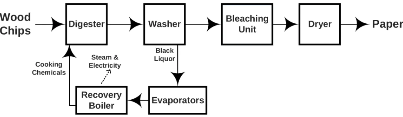
Kraft process, which is the dominant technique for the pulp and paper production world-wide, can be perfectly incorporated into the IF BR plant [3]. In a conventional Kraft mill, wood chips are cooked in a digester under strong alkaline and high temperature conditions resulting in delignification of wood. The cooked liquor goes to a washing step where pulp and residual liquors are separated. The pulp stream undergoes a bleaching process to increase its brightness and finally enters the drying step ; while, the residual stream, called black liquor (BL) is concentrated in a multi-stage evaporators and combusted in the recovery boiler to produce heat and steam and regenerate cooking chemicals (Figure 1.2). The average yield of a Kraft pulping mill is reported to be around 50% since half of the wood components (mainly hemicellulose and lignin) are dissolved in the BL and combusted in the recovery
boi-ler [4, 5]. Within the Kraft IF BR context, the hemicellulose and lignin can be extracted and converted to a board spectrum of bio-products and bio-chemicals [3]. In particular, a fraction of the lignin can be separated from the BL before the combustion stage and converted to value-added products such as biofuels and carbon fibers [6]. Furthermore, lignin extraction increases the capacity of the Kraft mill by decreasing the load of its recovery boiler [5].
Washer Dryer Recovery Boiler Digester Black Liquor Cooking Chemicals Steam & Electricity
Paper
Wood
Chips
Bleaching Unit EvaporatorsFigure 1.2 A schematic drawing of a conventional Kraft pulping process
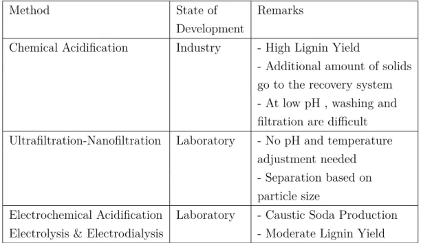
Different processes have been proposed for lignin extraction [7, 8, 9, 10, 11]. Among all of the suggested methods chemical acidification, ultrafiltration (U F ) and electrochemical acidification pathways have attracted more attentions [4, 9, 12, 13]. A summary of these three common techniques and their remarks is given in Table 1.1.
Chemical acidification is the most common lignin extraction technique in which lowering the pH of the BL causes lignin precipitation and separation. Utilization of CO2 and H2SO4 as
the acidifying agents remarkably enhanced the process yield [4, 5, 10]. However, there are some serious issues regarding the practical implementation of this acidification approach. For instance, the added chemical (acid) can disturb sodium-sulfur balance of the receptor mill. Furthermore, when CO2 is utilized, the price and the cost-intensive installation of the CO2
recapturing equipment would challenge the process productivity [4, 12].
U F and nanofiltration method, on the other hand, is still under investigation [9, 14]. A com-parison between the chemical acidification and U F separation techniques has been done by Uloth et al. [15] ; they concluded that the chemical acidification process has a higher efficiency as well as a lower cost. Moreover, application of the U F process resulting in separation of lignin with a specific molecular weight and to enhance the lignin extraction yield, another acidification step such as BL carbonation was required [5].
Table 1.1 Three main technologies for lignin extraction from black liquor
Method State of Remarks
Development
Chemical Acidification Industry - High Lignin Yield
- Additional amount of solids go to the recovery system - At low pH , washing and filtration are difficult Ultrafiltration-Nanofiltration Laboratory - No pH and temperature
adjustment needed - Separation based on particle size
Electrochemical Acidification Laboratory - Caustic Soda Production Electrolysis & Electrodialysis - Moderate Lignin Yield
Since the alkaline BL is an electrolyte solution containing inorganic salts (N aOH, N a2SO4,
N a2CO3 and N a2S) and organic compounds (lignin and hemicellulose) application of the
electrochemical acidification approach is another green alternative to overcome the disad-vantages of the chemical acidification method, acidify the BL and produce caustic soda as a valuable side-product [13, 16]. The electrochemical acidification of the BL can be performed in different forms : electrolysis (EL), conventional electrodialysis (ED) and electrodialysis with bipolar membrane (EDBM ). In all of the aforementioned processes, ion exchange mem-branes (IEM ) (memmem-branes having fixed positive or negative charges) are utilized to separate electrolyte solutions under an electric field as the driving force of an electric field. A specific type of the IEM s is bipolar membrane (BP M ), which is made of two ion exchange layers (IEL) of opposite charges. A BP M enables the electro-dissociation of water into protons and hydroxide ions and can be applied for the acid and base production from their salt solutions [17, 18, 19].
This PhD project is part of a broader research study which evaluates the possibility of lignin biorefinery implementation in existing Kraft pulping mills to improve their revenue, diversify their portfolio and make them sustainable in the long term. Therefore, the main objective of this thesis is to identify, design and develop an efficient and eco-friendly BL acidification method for lignin extraction which can be an attractive alternative to the chemical acidifi-cation technique and eventually integrated into an existing Kraft pulping mill. To this end, electrochemical acidification of the BL via EDBM process was selected as a promising and
sustainable pathway. The main focus of this research was to validate the concept, eliminate the process drawbacks and enhance the performance of the EDBM method in order to make it practically feasible for a large scale implementation. This PhD thesis is organized as follows : chapter 2 presents the relevant literature review. It introduces the concepts and theories which have been presented in the literature and were useful in this research work. Chapter 3 first presents the objectives and methodology and then describes the organization of the articles. The main results of this project are presented in chapters 4 − 8. Chapter 9 presents an additional study on a preliminary comparison between the chemical and modified electrochemical acidification approaches in order to provide a valuable knowledge about the advantages of EDBM method and allow us to reflect on the potential and operating window of this method as a sustainable option for the BL acidification and lignin extraction. Chapter 10 provides a general discussion and synthesizes the results obtained in the course of this study. Finally, chapter 11 summarize the most important conclusions of this study followed by recommendations for future work.
CHAPTER 2 LITERATURE REVIEW
2.1 Ion Exchange Membrane (IEM )
Membranes are called the heart of any membrane separation technologies and can be consi-dered as «a permselective barrier or interface between two phases» [20]. Ion exchange mem-branes (IEM ) are the key elements in electro-membrane processes. These memmem-branes are permeable to either negatively or positively charged ions in an aqueous solution. The IEM s are similar to the ion exchange resin in a sheet form. A membrane with fixed positive charges is called an anion exchange membrane (AEM ). Similarly, a membrane containing fixed ne-gative charges is a cation exchange membrane (CEM ) [18, 19].
The following charged groups are mainly used as fixed charges in AEM s : −N H3+, −N RH2+, −N R3+, −P R3+ and −SR2+ [18, 19].
And, in CEM s the fixed charged groups can be : −SO−3, −COO−, −P O2
3−, −P O3H− and −C6H4O− [18, 19].
Figure 2.1 represents a CEM containing fixed negative charged groups as well as the mobile cations which can be replaced by other cations existing in the solution close to the membrane. The counter-ion concentration within the membrane is high ; hence, most of the electric current is carried by counter-ions [21]. Based on Donnan exclusion phenomenon an ideal IEM must be impermeable to the co-ions [22].
Figure 2.1 A cationic exchange membrane (CEM ) with fixed carboxylic acid charges
In order to select a suitable IEM for an electro-membrane process, the membrane must have some desired properties such as [23] :
— High Permselectivity : an IEM should be highly permeable to counter-ions and im-permeable to co-ions.
— Low electrical resistance : the permeability of IEM for the counter-ions under the electric field driving force should be as high as possible.
— High chemical and thermal stability : the membrane should tolerate a pH range of 0 − 14, be mechanically strong and finally should possess a low degree of swelling. The properties of the IEM s are determined by two parameters : the basic polymer matrix and the type and concentration of the fixed ionic moieties. The basic polymer matrix determines the mechanical, chemical and thermal stability of the membrane. Usually, the matrix of an IEM consists of hydrophobic polymers such as polystyrene, polyethylene, or polysulfone. While these basic polymers are insoluble in water and show a low degree of swelling, they may become water soluble by the introduction of the ionic groups. Therefore, the polymer matrix of the IEM s is very often cross-linked. The degree of the cross-linking determines the degree of the swelling as well as the chemical and thermal stability, but it also has a significant influence on the electrical resistance and the permselectivity of the membrane [24].
Another type of IEM s is called bipolar membrane (BP M ) which contains the negatively fixed charged groups on one side and the positively fixed charged groups on the other side. As illustrated in Figure 2.2, water diffuses from both sides of the BP M to its transition layer and once an electric field is applied, water dissociation reaction takes place inside this layer and generates proton and hydroxide ions. These ions migrate to the aqueous solutions through the cation and anion exchange layers of the BP M [17, 18, 19].
H2O H++ OH− (2.1)
Normally, the cation and anion exchange layers of the BP M are made of the same materials as CEM s and AEM s, which can resist in a wide range of pH [25]. The two ion exchange layers (IEL) should facilitate the selective transport of the proton and the hydroxide ions generated from the water dissociation reaction. The presence of a catalyst in the transi-tion layer decreases the activatransi-tion energy of the water splitting since the catalyst generates reactive, activated complexes and provides a different reaction path. Usually, heavy metals ion complexes, such as zirconium, chromium and iron are used as the catalysts [17, 18]. In addition to the catalyst selection, the transition layer should also enjoy a certain surface roughness in order to improve the contact area of the BP M . Therefore, beside the aforemen-tioned fundamental properties for an acceptable IEM s, the BP M s should also have a high capacity for water splitting reaction [17].
--
+
ANODE
CATHODE
+ + + + + + +OH
-H
+H
2O
H
2O
Anion Exchange
Layer
Cation Exchange
Layer
Transition Layer
Figure 2.2 The structure of a Bipolar Membrane (BP M )
Different methods have been examined for the BP M s preparation such as loosely laminating [26], pressing [27], gluing the two IEM s [28], or casting one of the IEM on top of the other one [29].
Additionally, the IEM s can be also classified based on their structure as homogeneous and heterogeneous. The homogeneous membranes, are prepared by means of a direct introduction of the ion exchange components into the polymeric structure of the membranes. Thus, the ion exchange groups are evenly distributed on the surface of the membrane. On the other hand, the heterogeneous membranes are produced, firstly, by preparing a mixture of a fine powder of an ion exchange resin and a binder polymer and then, pressing and sintering the mixture at a high temperature. This preparation procedure resulting in a non-uniform distribution of the ion exchange groups on the surface of the membrane [18, 30].
2.2 Electro-Membrane Processes Used for Electrochemical Acidification
2.2.1 Membrane Electrolysis (EL)
Figure 2.3 shows a simple illustration of an EL cell. It is made of an anode compartment containing the anode and an anolyte solution, a CEM and a cathode compartment consisting of the cathode and a catholyte solution. In the EL process, both anodic and cathodic redox reactions are involved in the transfer of the charged ions. Therefore, these electrode reactions play an important role in the process. The CEM separates the cathodic and anodic com-partments in order to avoid unwanted reactions. The electrolysis of the N aCl for production of caustic soda and Cl− is known as the main industrial application of this method [31].
-An
o
d
e
C
a
th
o
d
e
Anolyte Catholyte+
-CEM
Figure 2.3 A simple membrane electrolysis (EL) cell
Generation of oxygen and hydrogen as side-product gases during the EL process consumes around 50 % of the electrical energy of the system. Therefore, in a large scale application, the collocation and storage of these gases as well as the high level of energy consumption would make the EL process energy and cost intensive. In addition, the requirement of an electrode pair for each repeating cell unit can increase the total cost of the process [32].
2.2.2 Conventional Elctrodialysis (ED)
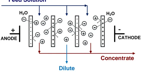
The principle of the conventional ED is illustrated in Figure 2.4, which shows an ED cell consisting of the CEM s and AEM s positioned in an alternating pattern between an electrode pair. When an ionic solution is pumped through the ED stack and the electric field is applied between the electrodes, the cations migrate towards the cathode and the anions go towards the anode. The cations pass easily through the CEM s but are rejected by the AEM s. Likewise, the anions migrate through the AEM s and are retained by the CEM s. Therefore, the ion concentration in alternate compartments increases, while the other compartments simultaneously become depleted. The exhausted solution is called dilute and the concentrated solution is called brine or concentrate. Any ED cell has five key elements [18, 19] :
— Electric Field, which causes the effective ion migration
— Electrodes, where the oxidation/reduction reactions occur to establish the driving force for the ion migrations inside the ED stack
— Ion exchange membranes (IEM ), the key components which allow the transfer of the counter-ions and reject the co-ions
electrodes and the IEM s
— Electrolytes, the current carriers between the electrodes
-+ + + + + + + -+ + + + + + + + + + + + + + + +
-H+ OH -H2O H2O
-+
ANODE CATHODEFeed Solution
Dilute
Concentrate
Figure 2.4 A flow-diagram of a conventional ED stack
Membrane fouling is considered as the main process drawback for most of the membrane separation techniques ; it adversely influence the efficiency of the process [30]. Fouling is caused by the formation of unwanted particles on the surface of the membrane. Generally, these foulants can be categorized into four different groups : colloids, organic matter, inorganic species and biofouling [33]. In an ED system suspended charged particles such as humic acids, surfactants, biological matters and polyelectrolytes can attach to the surface of the CEM s and AEM s and increase their resistance significantly [18, 34, 35, 36, 37]. However, several techniques have been suggested and applied to eliminate the membrane fouling in the ED stack. A summary of these methods is given in Table 2.1 [37].
Table 2.1 Applied methods for controlling and minimizing the fouling of the IEM s during the electromembrane processes [38]
Method State of Remarks
Development
Electrodialysis Industry - Cleaning in place (CIP )
Reversal (EDR) - A special system design is required to discharge the dilute and the brine streams
- Not applicable for the EDBM system due to the potential BP M damage
Pretreatment Industry - Removal of multivalent ions, high molecular weight particles and suspended solids
- Additional cost and energy due
to the installation of the pretreatment unit Chemical Cleaning Industry - Cleaning in place (CIP )
- Generation of an additional effluent - Additional cost and energy
- Some chemicals may affect the IEM integrity Modification Laboratory - Less power consumption
of IEM s - Less operation cost as no pretreatment step is required
- Expensive membranes Mechanical Action Laboratory - Cleaning in place (CIP )
(ultrasound, vibration, - Additional cost for the special equipment and air sparging) - May affect the IEM integrity
Pulsed Electric Laboratory - Cleaning in place (CIP )
Field (P EF ) - Diminishes concentration polarization effect - Simplicity installation
Over Limiting Current Laboratory - Cleaning in place (CIP )
Regime - Eliminates concentration polarization effect
- Requires less membrane area - May affect the IEM integrity
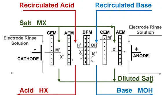
2.2.3 Elctrodialysis with Bipolar Membrane (EDBM )
The conventional ED can be coupled with the BP M s and used to produce acids and bases from their corresponding salts. In this process the CEM s and the AEM s along with the BP M s are placed in an alternating pattern inside an ED stack as shown in Figure 2.5. As mentioned earlier, when an electric field is applied across the stack, water splitting reaction takes place in the transition layer of the BP M . The generated protons and hydroxide ions enter acidic and basic compartments, react with anions and cations migrated from the salt solution (M X) and produce an acid (HX) and a base (M OH), respectively [17, 18, 19] :
M X + H2O HX + MOH (2.2)
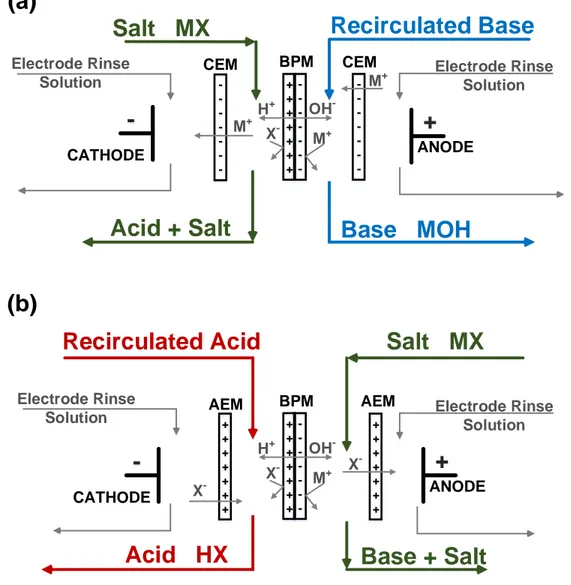
The type of application strongly influences the configuration of the EDBM cell. For example, if it is intended to produce an acid and a base simultaneously, a three-compartments EDBM cell is recommended. On the other hand, when it is not possible to produce acid and base with a high purity, a two-compartment EDBM cell is preferred . The three-compartment EDBM cell arrangement illustrated in Figure 2.5 is utilized for the simultaneous production of acid and base from their corresponding salt solution. The two-compartments cells which are applied for the base and acid generation are depicted in Figures 2.6 (a) and (b), respectively [18, 38]. -+ + + + + + + -+ + + + + + +
-
+
ANODE CATHODESalt MX
+ + + + + + + -Electrode Rinse Solution Electrode Rinse SolutionDiluted Salt
X -X -M+ M+ OH -M+ H+ X -BPM CEMCEM AEM AEM
Recirculated Acid
Recirculated Base
Acid HX
Base MOH
Similar to the conventional ED, membrane fouling can impair the productivity of the EDBM processes [37]. Most of the techniques listed in Table 2.1 ac also be applied to diminish the fouling phenomenon and sustain the IEM integrity throughout EDBM process.
--
+
ANODE CATHODESalt MX
+ + + + + + +-Acid + Salt
M+ M+ OH -M+ H+ X -BPM CEM CEMRecirculated Base
Base MOH
+ + + + + + + -+ + + + + + +-
+
ANODE CATHODESalt MX
+ + + + + + +Base + Salt
X -X -OH -M+ H+ X -BPM AEM AEMRecirculated Acid
Acid HX
(a)
(b)
Electrode Rinse Solution Electrode RinseSolution Electrode Rinse Solution
Electrode Rinse Solution
Figure 2.6 Two-compartments EDBM cell arrangement for production of (a) base and (b) acid from their corresponding salts
Besides the membrane fouling, poor permselectivity of the IEM s can also adversely affect the performance of the EDBM system. Figure 2.7, exhibits four different zones : in zone 1, the desirable process takes place ; while, in the rest of the zones, unwanted phenomena affect the current efficiency and hamper the EDBM performance. The loss of the permselectivity of the IELs of the BP M is shown in zone 2. This loss might diminish the purity of the end products. Zone 3 represents the permselectivity failure of the coupled CEM and AEM which can influence the overall process performance. The diffusional loss is depicted in zone
4, depending on the size of the molecules and structure of the IEM s. Weakly ionized small molecules such as HF , N H3 and SO2 may cause a concentration gradient and accordingly
diffusional failure [38].
Figure 2.7 Membrane permselectivity failure that can affect the EDBM performance [39]
2.3 Critical Literature Review
To the best of our knowledge, there are few scientific papers that report the electrochemical acidification of the Kraft BL. Most of the former studies in this area are quite old and do not provide a comprehensive information regarding the best process configuration, effect of the membrane properties, BL chemical composition and process conditions on the efficiency of the whole process. Moreover, due to an increasing attention to implementation of the mem-brane processes in recent years, there are more commercially available IEM s with improved specifications which can potentially fulfil the demands as suitable IEM s for the electrochemi-cal acidification of the Kraft BL. In the following sections, the electrochemielectrochemi-cal acidification methods are divided into three groups : electrolysis (EL), conventional electrodialysis (ED) and electrodialysis with bipolar membrane (EDBM ) techniques.
2.3.1 Electrolysis of Black Liquor
In an electrolytic acidification process, the BL is sent to the anode compartment and a diluted N aOH is fed into the cathode compartment of the EL cell and a CEM separates these two compartments. When the driving force, i.e., the electric field is applied, the sodium
ions go toward the cathode and combine with the hydroxide ions produced from cathodic reduction of water and form the sodium hydroxide. In the other compartment, the hydrogen ions, generated from the anodic oxidation of water, replace the sodium ions. The final main products of the EL system are the acidified BL and the concentrated caustic soda [16]. An overview of the EL acidification of the Kraft BL is shown in Figure 2.8.
CEM Na+ _ Cathode + Anode OH -H+ BL Diluted NaOH Concentrated NaOH Acidified BL O2 H2
Figure 2.8 Basic operation of the BL electrolysis acidification process
Cloutier et al. [13, 39, 40] performed a laboratory research on the EL acidification of the Kraft BL in batch and continuous operational modes. Their studies also covered the effect of the process parameters such as the anode material, current efficiency, operational temperature and the type of the Kraft BL on the energy efficiency of the EL process. They concluded that the EL of the Kraft BL process is technically possible but further investigations are required in order to optimize the current density and increase the process efficiency. Furthermore, precipitation of organic materials on the surface of the anode is mentioned in former studies on the EL of the Kraft BL [16, 39, 40, 41]. This precipitation caused anode’s fouling which led to a rapid increase in the voltage drop across the EL cell.
In 2005, Nergo et al. [16] conducted a study on the electrolytic treatment of straw weak BL in a batch mode. They claimed that the anode fouling can be prevented by working under a high current density and a high velocity as well as employing two P t wire electrodes parallel to the flows inside the EL cell. They also reported that performing the EL process at a higher operational temperature may increase the current efficiency [16].
2.3.2 Electrodialysis of Black Liquor
In a three-compartments ED cell that is illustrated in Figure 2.9, the BL is fed into the central compartment and the distilled water is sent to the electrode compartments of the cell. Under the electric field, the positively charged ions cross the CEM and proceed towards the cathode ; conversely, the negatively charged ions pass the AEM and go towards the anode. The outlet streams of this process are the treated BL and soda [42].
Water BL Water O2 CEM AEM H2 OH -Na+
+
-HCO3 -SO42-Figure 2.9 Electrodialysis of black liquor in three compartment arrangement
Mishra et al. [42, 43] were one of the pioneer research groups who explored the technical feasibility of ED treatment of an alkaline BL in batch and continuous modes. They examined the effects of the current density, pH, residence time (in batch operation) and amount of recovered soda with the three-compartments ED stack. They proposed to use the amount of the energy consumption as a criterion for choosing the best operating conditions. In term of the flow velocity, they reported that at a low flow velocity a higher amount of the soda was recovered and less energy was consumed ; however, performing the ED process at a low velocity resulted in more pronounced anode fouling.
In 2013, Cloutier et al. [44] performed the conventional ED treatment of the Kraft BL em-ploying an ED stack made of four pairs of the AEM s and CEM s placed in an alternating pattern between the electrode pair. They indicated that the ED treatment process cannot completely neutralize the alkalinity content of the Kraft BL solution and as a result this technique can only demineralize the Kraft BL, to some extent. Therefore, another acidifica-tion step is required to complete the acidificaacidifica-tion process and drop the pH of the Kraft BL to a point that lignin can be extracted from it, efficiently [44].
2.3.3 Electrodialysis of Black Liquor using Bipolar Membrane
The EDBM acidification of the BL attracted less attention in previous studies due to the lack of suitable and available BP M s for this process. In 1990, Koumoundouros et al. [45] carried out a laboratory feasibility study on the recaustization of the oxidized Kraft BL using EDBM technique. They built their experimental set-up to obtain information about the current efficiency, energy consumption per gram of produced caustic soda and an estimation of membrane fouling and life time. Prior to the EDBM process, they conducted the CO2
acidification to drop the pH of the Kraft BL to 9 ; afterwards, two filtration steps were done followed by another acidification with sulfuric acid to lower the pH to 2 in order to extract the lignin (Figure 2.10). The outcome of their investigation can be summarized as follow :
— With regards to the type of the Kraft BL (softwood vs. hardwood), they observed that working with softwood Kraft BL yielded a better current efficiency than with hardwood.
— Further investigation is required to optimize the energy consumption and the stack configuration to make this process ready for the pilot scale.
CHAPTER 3 OBJECTIVES AND METHODOLOGY
As mentioned in the critical literature review, there are limited scientific studies that have addressed the electrochemical acidification of Kraft BL, particularly by means of the EDBM process. Most of the former studies are quite old and do not provide comprehensive infor-mation regarding the best process configuration, effect of IEM s, BL chemical composition and operational conditions on the efficiency of the whole process. On the other hand, due to an increasing attention to the membrane processes, nowadays, there are more commercially available IEM s and BP M s with improved properties which may answer the demands for electrochemical acidification of the Kraft BL. Therefore, the main objective of this research project was defined as follow :
3.1 Main Objective
To identify, design and develop an eco-efficient and efficient process to acidify Kraft black liquor and effectively extract lignin.
In order to accomplish the main objective three specific objectives are formulated :
— Specific Objective 1 : To propose and validate a new green technology for Kraft
black liquor acidification and efficient lignin extraction
— Specific Objective 2 : To evaluate the performance of the proposed process as a function of membrane properties, black liquor chemical composition and operational conditions
— Specific Objective 3 : To enhance the process performance in terms of high efficiency and low chemical and energy consumption and diminish membrane fouling
3.2 Methodology
In order to achieve the specific objectives and eventually the main objective, this research project was divided into three main phases as illustrated in Figure 3.1.
Phase I: Feasibility Study
To evaluate the technical feasibility of the EDBM process To identify the process obstacle(s)
To explore origin of the process obstacle(s)
Phase II: Process Configuration
To demonstrate the influence of the following parameters on the efficiency of the EDBM process:
o Specifications of the bipolar and cation exchange membranes and their durability
o Black liquor chemical composition o Operational temperature
o Hydrodynamic conditions
Phase III: Yield Enhancement
To suppress the membrane fouling and intensify the acidification process
To minimize the chemical consumption To improve process efficiency
To decrease energy consumption
Figure 3.1 A representation of overall methodology phases
Phase I - Feasibility Study : As stated in chapter 1, a portion of lignin can be extracted
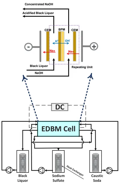
from the black liquor (BL) prior to the combustion step and converted to a wide spectrum of value-added products. In addition, lignin extraction from the BL also enhances the capacity of the mill by lowering the load of its recovery boiler. In order to perform this extraction, identification, design and development of a suitable BL acidification process is mandatory. The proposed method must accomplish the requirements in terms of a high efficiency, a low chemical and energy consumption along with environmental constrains. To this end, applying electrochemical acidification of Kraft BL via electrodialysis with bipolar membrane (EDBM ) seems to be a promising eco-efficient approach due to its low level of chemical and energy consumption. Furthermore, acidifying the BL in the EDBM system produces caustic soda which can be used in the Kraft process or other industries. However, to evaluate this preposition and validate the proposed method a technical feasibility study is imperative.
This study must demonstrate the advantages of the EDBM method and detect its main drawbacks. Based on the results of this study we can look for appropriate efforts to minimize the obstacles and enhance the process efficiency.
Phase II - Process Configuration : As explained in the literature review, IEM s are
one of the key elements of the EDBM system. Therefore, the first step of this phase involves in screening the most reliable and commercially available IEM s and evaluating their perfor-mances during the electrochemical acidification process. In addition, in the presence of the membrane fouling, identification and selection of the most appropriate cleaning procedure is prime important.
The final step of this phase determines the influence of the operational process variables on performance of the EDBM . In principle, process conditions play an important role in controlling the fouling of the membranes and performance of the membrane-based technolo-gies. The productivity of an EDBM process is governed by various parameters. The nature of the feed solutions and desired quality of the products determine a number of these para-meters, while some process variables such as applied current density, electrical conductivity, viscosity and operational temperature of the feed solutions can be varied in specific ranges based on the stack and IEM s properties and limitations. The obtained results of this phase enables us to enhance the process efficiency and minimize the membrane fouling.
Phase II - Yield Enhancement : Based on the findings of the previous phases adequate
efforts need to be taken in order to eliminate any kind of membrane fouling during the EDBM process and minimize the chemical consumption, co-ion leakages and improve the current efficiency of the process.
3.3 Presentation of Publications
The five following chapters present the main results of this thesis. The first article is presented in chapter 4. It describes the technical feasibility of the electrochemical acidification of the Kraft BL and is entitled «A Feasibility Study of a Novel Electro-Membrane Based Process to Acidify Kraft Black Liquor and Extract Lignin». This article have been submitted to Process Safety and Environmental Protection Journal.
Article 2 presents a comprehensive microscopic study on the fouling identification of the IEM S during the electrochemical acidification process. The mechanisms of the lignin colloidal fouling has been elucidated in this article. This article has been submitted to Journal of Colloid and Interface Science.
and Chemical Cleaning on Ion Exchange Membrane Integrity» and has been submitted to ACS Sustainable Chemistry & Engineering Journal. In this article, the effects of fouling and chemical cleaning cycle on the IEM s’ integrity were investigated. The one of the main goals of this work was to fundamentally understand the cleaning mechanisms and evaluate the impact of the cleaning solutions on foulants removal for different types of commercially available IEM s, in order to select the most reliable IEM s as well as the proper cleaning conditions for the chemical cleaning step of the EDBM process.
The «Effect of Process Variables on the Performance of Electrochemical Acidification of Kraft Black Liquor by Electrodialysis with Bipolar Membrane» is presented in Article 4. This article has been submitted to Chemical Engineering Journal.
Article 5 describes the results of the successful application of an in-line cleaning step on suppression of the lignin colloidal fouling and intensification of the electrochemical acidifica-tion process. This article is entitled «Electrochemical Acidificaacidifica-tion of Kraft Black Liquor : Impacts of Pulsed Electric Field Application on Bipolar Membrane Colloidal Fouling and Process Intensification» and has been submitted to Journal of Membrane Science.
«Black Liquor Acidification for Lignin Extraction : A Preliminary Comparison between Che-mical and ElectrocheChe-mical Acidification Pathways» is presented in chapter 9. This chapter is considered as an additional study reporting the assets of the green and sustainable elec-trochemical acidification pathway. It gives suggestions for further improvements of the lignin aging and filtration steps. The results of this chapter may be extended into an article and will be submitted for a publication.
![Table 2.1 Applied methods for controlling and minimizing the fouling of the IEM s during the electromembrane processes [38]](https://thumb-eu.123doks.com/thumbv2/123doknet/2332338.32005/29.918.106.822.171.998/table-applied-methods-controlling-minimizing-fouling-electromembrane-processes.webp)
![Figure 2.7 Membrane permselectivity failure that can affect the EDBM performance [39]](https://thumb-eu.123doks.com/thumbv2/123doknet/2332338.32005/32.918.198.727.212.514/figure-membrane-permselectivity-failure-affect-edbm-performance.webp)
![Figure 2.10 The BL recaustization steps performed by Koumoundouros et al. [46]](https://thumb-eu.123doks.com/thumbv2/123doknet/2332338.32005/35.918.136.788.542.719/figure-bl-recaustization-steps-performed-koumoundouros-et-al.webp)