HAL Id: hal-01602598
https://hal.archives-ouvertes.fr/hal-01602598
Submitted on 13 Dec 2017
HAL is a multi-disciplinary open access
archive for the deposit and dissemination of
sci-entific research documents, whether they are
pub-lished or not. The documents may come from
teaching and research institutions in France or
abroad, or from public or private research centers.
L’archive ouverte pluridisciplinaire HAL, est
destinée au dépôt et à la diffusion de documents
scientifiques de niveau recherche, publiés ou non,
émanant des établissements d’enseignement et de
recherche français ou étrangers, des laboratoires
publics ou privés.
Distributed under a Creative Commons Attribution - ShareAlike| 4.0 International
License
Efficiency of high energy over conventional milling of
granulated blast furnace slag powder to improve
mechanical performance of slag cement paste
Ahmed Bouaziz, Rabah Hamzaoui, Sofiane Guessasma, Ridha Lakhal, Djamel
Achoura, Nordine Leklou
To cite this version:
Ahmed Bouaziz, Rabah Hamzaoui, Sofiane Guessasma, Ridha Lakhal, Djamel Achoura, et al..
Effi-ciency of high energy over conventional milling of granulated blast furnace slag powder to improve
mechanical performance of slag cement paste. Powder Technology, Elsevier, 2017, 308, pp.37-46.
�10.1016/j.powtec.2016.12.014�. �hal-01602598�
Ef
ficiency of high energy over conventional milling of granulated blast
furnace slag powder to improve mechanical performance of slag
cement paste
Ahmed Bouaziz
a, Rabah Hamzaoui
b, So
fiane Guessasma
c,⁎
, Ridha Lakhal
d, Djamel Achoura
d, Nordine Leklou
e aCivil engineering research laboratory, University of Biskra, Biskra, Algeriab
Université Paris-Est, Institut de Recherche en Constructibilité, ESTP, 28 avenue du Président Wilson, 94234 Cachan, France c
INRA, Research Unit BIA UR1268, Rue Geraudiere, F-44316 Nantes, France d
Materials and Environment laboratory, University of Annaba, Algeria e
LUNAM, Université de Nantes– IUT Saint-Nazaire, GeM, CNRS UMR 6183, Research, Institute in Civil Engineering and Mechanics, France
This work aims at bridging the efficiency of ball milling of granulated blast furnace slag (GBFS) to the structural and mechanical properties of slag cement pastes. Both conventional and high energy milling of GBFS are consid-ered with a milling duration varied between 1 and 10 h. X-ray diffraction, infra-red spectroscopy, granulometry analysis and scanning electron microscopy are used to draw the main lines of structural and morphological changes occurring during milling. Cement pastes formulated using 45% of GBFS in substitution are characterized. Workability, X-ray diffraction analysis, differential scanning calorimetry and compressive testing are performed to analyse main structural changes and reactions driven by the presence of milled GBFS as well as its direct con-sequence on the mechanical strength of slag cement pastes. Slag milling indicates the superior efficiency of high-energy milling, which allows a maximum slagfinesse of 1.79 m2/g after 3 h of milling. Major structural changes
occur during thefirst 3 h of high energy milling while conventional milling does not induce any remarkable trend. These changes concern amorphisation of the bulk structure in addition to the fracturing and agglomeration of slag particles. Workability of slag cement pastes is remarkably improved when using 1 h of high-energy slag milling. This result is consistent with slagfinesse trend with respect to milling time and with the improvement of GBFS reactivity. The substitution of 45% of cement (CEM I 52.5) by GBFS is only beneficial at the condition of performing high-energy milling for at least 1 h.
Keywords:
Granulated blast furnace slag High-energy ball milling Cement paste Compressive strength Structural characterisation
1. Introduction
In extractive metallurgy, blast furnace slag (BFS) forms as a result of melting of iron oxides (raw ore, pellet, sinter) in blast furnace. Besides its role during iron smelting for assisting impurity removal from the ore, slag is used as an industrial by-product in several applications. In civil engineering, slag invaded two major markets, namely cement pro-duction and road construction. In particular, the market uptake justified major research direction for slag as a cement additive. For instance, Bell-man and Stark[1]report the beneficial effect of slag on mechanical per-formance of slag mortar at an early age subject to appropriate activation. In chapter one of a book dedicated to by-products, Siddique[2] pro-motes the benefits of using Ground Granulated Blast Furnace Slag
(GGBFS) in cement. More than a dozen of good reasons are exposed there such as good workability, improved strength and durability, resis-tance to sulphate attack, etc. Slag beneficial role on environment is re-ported by different contributors[3–5]. The use of slag as substitute is expected to reduce the environmental footprint of clinker manufactur-ing with a rate as large asfive times less of CO2emission. This kind of
substitution contributes to sustainable cement production since the construction sector is recognized as a large source of carbon emissions
[6].
Different recycling routes of slag appear in the literature like the hy-drothermal hot pressing explored by Yanagisawa et al.[7]. Their study shows that both pressure and water content are major influential pro-cess variables on tensile strength and bulk density of slag compacts compared to the reaction time.
Ozbay et al.[3]expose some critical factors, which act as leverage of slag hydraulic activity and heat of hydration. These are related to the chemistry of the slag, its degree offinesse and substitution ratio. The chemistry of the slag can be adjusted using activators such as NaOH.
⁎ Corresponding author.
E-mail addresses:ad.bouaziz@gmail.com(A. Bouaziz),rhamzaoui@estp-paris.eu
(R. Hamzaoui),sofiane.guessasma@inra.fr(S. Guessasma),ridhalakhal@yahoo.fr
Activators play a central role in producing CSH phases. Their concentra-tions modulate the degree of reactivity of slag as shown by Hilbig and Buchwald[8]. Complex hydration mechanisms take place during slag activation. These are responsible for the cleavage of the slag network and production of several mineral phases[9]. The understanding of the hydration mechanisms is important to anticipate reactivity of slag with cementitious materials. Soft X-ray transmission microscopy shows that development of hydration products in terms of morphology and growth rate is affected by the nature of activation suspensions[10]. According to the BFS cooling process, several types of slag can be structurally distinguished. Slag may appear as amorphous, crystalline or some combination of both[7,10–14]. If cooling is slow such as in free air, slag is grey, porous and exhibits a crystallized structure. Howev-er, if cooling is fast, such as when using water quenching[11], slag be-comes vitrified.
Slag is referred as granulated slag when subject to grinding accord-ing to the standard NF IN 15167-1[15]. Granulated blast furnace slag (GBFS) has a morphological form of clear-colour sand. GBFS shares the same main chemical compounds (mainly SiO2, CaO, Al2O3, MgO)[2,11,
16–20]as ordinary Portland cement[20–23]. GBFS has a direct utiliza-tion as additive in cement with rates varying from 6% up to 95% for CEM II and CEM III according to the norm NF EN 197-1[22,23].
Mechanical strength improvement of slag concrete is not subject to major debate but a large discrepancy is observed for reported gains
[11,24]. Jelidi et al.[11]show that only minor gain in compressive
strength (b4%) is expected for slag concrete after 28 days. Concrete mix-tures with GGBS allow only 15% of gain in long term (one year) com-pressive strength according to the work of Seleem et al.[24].
The gain in mechanical performance is a challenging issue since the compressive strength of cement containingN95% of clinker (CEM I) is nearly 53 MPa after 28 curing days[22,25]. Compared to other cement types containing high rates of slag such as CEM II (6%–35%) or CEM III (36%–95%), compressive strength decreases by 19% to 38%.
The challenge of increasing mechanical performance of slag cemen-titious materials is addressed in different ways. El-didamony et al.[20]
considered different combinations of Portland cement, GBFS (ground granulated blast furnace slag) and drinking water sludge in the formu-lation of cement pastes. Compressive strength as large as 90 MPa is achieved for those pastes containing higher contents (N24%) of GBFS after 30 days of curing. The strategy of using additional phases to further increase the strength does not often pay. Seelem et al.[24]show that multi-phase mixtures involving GGBS (ground granulated blast furnace slag) is not suitable to for long term strength degradation under seawa-ter attack. Their results indicate that GGBS alone is the most efficient ad-ditive against strength deterioration with only 3% of strength decrease after a year of exposure to sea water environment. Bellman and Stark
[1]show that overcoming low early stage compressive strength of mor-tar is possible if hydration of slag is better improved. The authors show that the use of different salts resulting in the increase of pH improves the compressive strength of slag mortar byN166% after 2 days of curing. The gain in strength represents 47% at an age of 28 days. Abdalqader et al.[26]considered alkali activation offly ash/slag to improve the perfor-mance of cement using sodium carbonate. The best compressive strength trend with curing time is achieved when 10% of Na2CO2is
added to GGBS with 80 MPa as the highest score after 90 days. GGBS reactivity with water under alkali environment as well as with calcium hydroxide determines the strength trend at early age upon the formation of hydration products[2]. Modulation of this reactivity using activation is certainly a promising pathway for improving strength of slag cementitious materials. Numerous ways of activation are reported in the literature, most of them rely on alkali activation[8,9]. Salman et al.[27]studied the effect of Na-silicate, KOH and NaOH activation of steel slag mortar. They achieved substantial rate of improvement of early age compressive strength (after 3 days of steam curing) with Na-silicate-NaOH compared to K-silicate-KOH activation. Despite the statement of the authors on the relatively moderate gain in strength
(maximum strength 43 MPa) at long term curing (90 days), the reading of their results still indicate beneficial effect of alkali activation.
Both calcium sulphate addition[1]and chemical activation are also privileged ways to use efficiently slag in cementitious materials[15]. Dimitrova et al.[13]studied slag activation towards metal ions using thermal treatment. They demonstrate that copper removal is positively correlated to the slag heating temperature. Grinding techniques are also used as mechanical activators[28–33]. These techniques increase slag finesse, its specific surface area and thus they are expected to signifi-cantly affect pozzolanic and hydration kinetics. Wan et al.[28]used dif-ferent types of grinding including ball, airflow and vibromill to relate GGBSfinesse to strength of slag mortar. Highest finesse scores (i.e., smallest average diameter and largest surface area) are attributed to vibromill processing. The authors show that this grinding process re-sults in largest compressive andflexural strengths of slag mortars.
Kriskova et al.[29]studied the effect of bead milling on mechanical activation of steel slag. Besides the substantial increase in surface area and amorphisation of slag, their study show that slag mortars exhibit different curing trends depending on the type of slag. However, me-chanical activation demonstrates insufficient gain in both compressive andflexural strengths. Kumar et al.[30]introduced surface activation criterion in addition to specific surface area as a factor influencing me-chanical activation efficiency of slag. The authors show that surface ac-tivation potential is nonlinearly correlated to milling time for maximum durations of 60 min[30]. Significant modulation of the hy-dration kinetics is obtained from non-reacted to complete hydrated slag. The result of such activation on mechanical performance of cemen-titious materials is, unfortunately, not considered by the authors. Allahverdi and Mahinroosta[31]attempted such study in the case of high phosphorous slag cement. The authors achieve compressive strengths as large as 120 MPa for slag mortar at an age of 180 days. This substantial improvement of compressive strength can be related to the large milling durations attempted by the authors (up to 18 h). It appears also from the results of the authors that the intensity of the milling reflected by the finesse is monotonously correlated to mechan-ical strength of slag mortar. Bougara et al.[32]combined similarfinesse (between 250 and 420 m2/kg) of granulated blast furnace slag with
al-kali activation (using NaOH and KOH). Compressive strength results achieved by the authors are below 50 MPa at an age of 90 days and for slag content up to 50%. The authors considered also the effect of cur-ing temperature between 20 °C and 60 °C[32]. They noticed the reduc-tion of compressive strength with the increase of curing temperature even if they recommend the use of 40 °C as a curing temperature for an optimal strength increase trend. Behim and Clastres[33]correlated El Hadjar slag content (0–100%) and finesse (2500–4000 cm2
/g) to the compressive strength of slag mortars. The largest compressive strengths are related to the largestfinesse and smallest content of slag (10%). Strength scoresb56 MPa are achieved for the best formulations after 90 days of hydration.
With classical or conventional grinding slagfinesse does not exceed 5000 cm2/g after 24 h of milling[32,33]. High energy ball milling allows superior results (up to 9700 cm2/g in[29]and 8000 m2/g in[30]).
The analysis of the literature work on mechanical activation of slag cementitious materials shows that sparse information is provided about the structural justification of mechanical strength trends of slag cementitious materials. With no intention to diminish the quality and significant outcome of the research work attempted by several contrib-utors, the focus of some of them on morphological analysis is obvious. This is assuredly related to the direct consequence of grinding on parti-cle size and specific surface area analysis[28,32]. Some other contribu-tors addressed the result of slag grinding process through various instrumental techniques such as XRD, calorimetry and infra-red (FTIR) analysis but bounded their interest to slag rather than slag in cementi-tious materials[29]. And some others were able to correlate the result of low energy grinding to structural analysis (XRD, calorimetry, TEM, FTIR)[30,31]. In this work, we propose to address this gap in structural
analysis of high energy ball milling activation of granulated blast fur-nace slag as well as its consequence on mechanical performance of slag cement pastes. The mechanical activation is considered here through high energy planetary ball mill thanks to friction mode process described in an earlier work[34]. The outcome of high energy milling is compared to classical milling of GBFS to highlight main differences. Sub-stitution of cement CEM I by GBFS with a ratio as large as 45% is attempted. Knowing that CEM I contains large content of clinker (up to 95%), this substitution is intended to formulate more sustainable ce-ment. This work addresses the intensity of pozzolanic reactions, which are expected to be modulated by grinding parameters of GBFS. 2. Materials and methods
The major raw materials are cement CEMI 52.5 CP1 NF EN 197-1 from Calcia and granulated blast furnace slag provided by ArcelorMittal Algeria, SPA. The chemical composition of milled granulated blast fur-nace slag (GBFS) is performed using X-rayfluorescence spectroscopy. These experiments are carried out using the S2 RANGER instrument from Bruker and results are shown inTable 1. The chemical composition is also monitored during slag milling. This milling is carried out using both high energy and classical ball milling machines. High energy mill-ing is based on planetary high-energy ball mill RETSCH PM400 from Retsch Company whereas conventional milling is based on Eberhard Bauer apparatus operating at a speed of 50 rpm. The milling is per-formed using steel balls having a diameter between 20 mm and 50 mm in diameter for duration of 10 h. The capacity of the milling con-ventional equipment is 0.05 m3, which allows processing 2 kg of slag in
a single shot. High energy milling apparatus is composed of four vials mounted on a planar disc. The rotation of the disc is adjusted to 400 rpm. Vials rotation is in the opposite direction with a speed of 800 rpm. The milling time t is varied in the range (1–9) hours. Grinding energy is transmitted to the slag using steel balls of 30 mm in diameter. The steel vial capacity is 500 ml. The weight of powder samples is ad-justed to 200 g per vial whereas the ball-to-powder weight ratio is 4. Sealing is operated to avoid air contamination during milling process. Metal contamination is also managed by imposing a delay of 30 min after each hour of milling. This contamination emerges from iron or chromium release from the balls, vials or both.
Formulation of the reference cement paste is performed using mix-ture of cement (C) and water (W) with W/C content ratio of 0.3. Slag ce-ment pastes are prepared with a substitution ratio of 45 wt.%. Mixture of cement (C), grinding slag (GS) and water (W) is prepared using a con-stant proportion throughout the formulations with a ratio W/L of 0.3 where L = C + GS.
Cement paste mixtures are poured into right-prism moulds of di-mensions 4 × 4 × 16 cm3. Samples are unmould after 24 h, cut into 3
cubes of 4 × 4 × 4 cm3and stored in water vats at temperature of 20 °C. X-ray investigation is performed using Bruker D2 phaser diffractom-eter with a continuous scanning mode and Cu Kα radiation (λ = 0.1541 nm). The lines are measured in the 2θ range (5–100)° by an in-crement of 0.02° for 15 s. The software used for building the X-ray dif-fraction diagrams is DIFFRAC.EVA with ICDD PDF2. Sampling from the same vial is performed to achieve reliable X-ray diffraction diagrams as function of milling time. Sampling is repeated four times for the
slag powders and two times for cement pastes. The change in lattice pa-rameters of calcium hydroxide (portlandite) Ca(OH)2is calculated from
thefitting of X-ray patterns using Winnel software. This fitting con-siders the shift of the high angle diffraction line for all X-ray patterns using Bragg's law. The crystallite size D is calculated using the XRD pro-file analysis determined by Williamson–Hall method[35]. More details concerning calculation method are available in[36]. IR spectroscopy is performed at room temperature using Thermo Scientific Nicolet IS10 in-strument equipped with Smart iTR (with Diamond Plate) accessory. The spectra are processed using Omnic software.
Granulometer Laser LS 230 is used to determine particle size distri-butions within the range (0.04μm–2000 μm). Brunauer–Emmett–Teller (BET) adsorption method and Gemini VII 2390 Micrometrics instru-ment are considered to measure the specific surface area of milled slag. Due to limits of the apparatus, unmilled slag is sieved to achieve particle size smaller than 300μm. Analysis of specific surface area is per-formed using static volumetric technique working on the principle of gas pressure balance. The internal volume and the temperature sur-rounding both tubes are maintained at identical conditions. The mor-phology of unmilled and milled powders are characterized using scanning electron microscopy (SEM) EVO40 (Carl Zeiss®) with a Bruker energy-dispersive spectrometer (EDS). The enthalpy changeΔH is de-termined using Differential Scanning Calorimetry based on NETZSCH DSC 04 F1 Phoenix equipment. Samples of about 20–25 mg are sealed in aluminum crucibles and heated at a rate of 20 °C/min under a nitro-genflow rate of 20 ml/min in the sample chamber and 70 ml/min rate in the furnace chamber. The total heat is measured in a wide tempera-ture range (25–600) °C.
Mechanical testing is carried out using 3R 250 kN equipment. Com-pression testing is performed on cement paste samples of dimensions 4 × 4 × 4 cm3at different curing times (7, 28 and 120) days. For each
milling condition, 3 replicates are considered.
Workability of fresh slag cement paste is investigated using flowtable test according to the NF EN 1015-3 norm[37]. Theflow test uses a standard conical frustum shape with a diameter of 10 cm. The mould is centered on theflow table and filled in a two stage process with fresh cement paste. It is lifted vertically and temped 15 times dur-ing 15 s. The relative change in diameter of the cement paste is moni-tored to achieveflow or consistency evolution є (%) following the expression:
ε %ð Þ ¼ d−dð 0Þ=d0 ð1Þ
where d is the diameter of the cement paste after 15 times tamping, d0= 10 cm is the initial diameter.
3. Results and discussion
3.1. Morphology and structural properties of milled slag
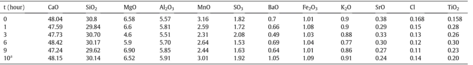
Table 1shows the results of chemical composition monitoring of
GBFS as function of milling duration using high-energy ball milling. Also are reported the composition of the unmilled and the milled GBFS using the conventional milling.Table 1confirms no traces of iron or chromium contamination. The composition of the as-received slag
Table 1
Chemical composition of GBFS for all milling conditions.
t (hour) CaO SiO2 MgO Al2O3 MnO SO3 BaO Fe2O3 K2O SrO Cl TiO2
0 48.04 30.8 6.58 5.57 3.16 1.82 0.7 1.01 0.9 0.38 0.168 0.158 1 47.59 29.84 6.6 5.81 2.59 1.72 0.66 1.08 0.9 0.29 0.15 0.28 3 47.73 30.70 4.6 5.51 2.31 2.08 0.49 1.03 0.88 0.33 0.13 0.26 6 48.42 30.17 5.9 5.70 2.64 1.53 0.69 1.04 0.77 0.30 0.12 0.30 9 47.24 29.62 6.90 5.85 2.44 1.63 0.64 1.01 0.86 0.27 0.11 0.23 10a 48.15 30.14 6.52 5.91 3.01 1.92 1.05 1.09 0.91 0.24 0.14 0.20 a Conventional milling.
contains a typical high rate of lime (CaO), a large content of silica (SiO2),
a low content of alumina (Al2O3) and magnesia (MgO). These are the
most representative species of the studied slag as they explain 94% of the composition. The unmilled slag is also typical to what is reported in the literature about blast furnace slag aggregate[2,11,16–20]. Only slight changes in the oxide contents are not to be mentioned.
The effect of milling on slag composition is rather minor. Major ox-ides composing the slag for which the content is larger than 5% do not exhibit significant change (almost 10% of variation) if we exclude mag-nesia (MgO) content which shifts from 6.58% down to 4.6% after 3 h of milling (30% of variation). Furthermore, manganese oxide (MnO) con-tent change oscillates between 16% (concon-tent of 2.64% at t = 6 h) and 27% (content of 2.31% at t = 3 h) with no consistency of the trend with the milling time.
Fig. 1compares XDR patterns of processed GBFS using both
conven-tional and high energy ball milling. The spectra relative to high energy milling are differentiated using the milling time (t). XRD pattern corre-sponding to t = 0 h refers to the pattern of the as-received GBFS. This latter pattern shows diffuse scattering signature of the amorphous GBFS structure identified from the broad diffuse hump peak in the inter-val 2θ between 20° and 40°. This pattern is reported in the literature as a typical characteristic of the vitreous structure of GBFS due to the pres-ence of glassy fractions[17,19,33,38]. The XRD pattern of the as-re-ceived GBFS shows the presence of vaterite mineral form of CaCO3
identified from the peaks (112) and (008) at 2θ = 27.1° and 42.8°, re-spectively. XRD pattern of GBFS similar to the one studied here issued from (same provenance than our GBFS),
Behim et al.[33]report XRD (CoKα radiation) spectra of El-Hajar GBFS similar to the one studied here. The authors identify the two dif-fuse hump peaks at approximatively 2θ = 20°–48° and 2θ = 46°–68°. The same authors[33]report crystallized minerals like calcite, iron and traces of gehlenite (C2AS) or akermanite (C2MS2) within the
amor-phous bulk. XRD patterns of GBFS from Taiyuan steel company in China
[9]issued using CuKα irradiation places the broad diffuse hump peak in the region of 2θ between 20° and 38°. Zhang et al.[9]shows the pres-ence of four kinds of mineral phases, namely akermanite, gehlenite, cal-cium silicate, and merwinite.
Structural modifications inferred to conventional milling can be read
fromFig. 1. We observe a shift by 3° of the diffuse hump peak to the
range 2θ (23°–35°). This shift is accompanied by the appearance of the mineral calcite containing the most thermodynamically stable form of CaCO3. Calcite is identified by the peak (104) at 2θ = 29.4°. As for
high-energy ball milling, complete amorphisation of the bulk material is achieved after thefirst hour of milling. Both conventional and high-energy milling have comparable diffuse scattering signature. The differ-ence between the two milling processes comes from the large milling duration (10h) required by conventional milling to achieve the same amorphisation degree resulting from only 1 h of high energy ball milling.
The superior result of high-energy milling is explained by the in-tense nature of the repeated welding and fracturing of the powder mix-ture. During high energy milling, severe plastic deformation process of the powder particles takes place stimulated by ball-particle-ball and ball–particle vial wall interactions[39,40]. These results compare fairly with the general trend of amorphisation reported by Kriskova et al.
[29]on slag bead milling for 6 h. The authors[29]observe also differ-ences between minerals in terms of degree of amorphisation.
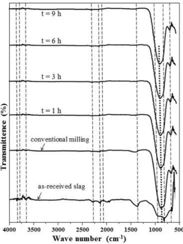
Fig. 2compares infrared spectra of GBFS using both ways of milling.
Assignment of peak bands of the as-received GBFS is provided by the
spectral search feature implemented in the Thermo Scientific Omnic se-ries software. The search performed with a sensitivity of 80% delivers the assignments summarized inTable 2. These are also highlighted by dash lines inFig. 2. All OH groups identified in the band width 4000– 2500 cm−1for the as-received slag show up for all milling conditions but with slight shifts and smaller intensities. In the range 2500– 2000 cm−1, C\\O and H\\O\\H stretching modes are present in the raw material. These also resist both conventional and high energy mill-ing except at the position 2017 cm−1. This band peak disappears after both types of milling. In the range 2000–500 cm−1, the band position
at 1419 cm−1is assigned to the symmetric stretching mode of the O\\C\\O bond (Table 2). This stretching bond is identified at a different position (1450 cm−1) by Abdalqader et al.[26]. Conventional milling shifts the peak form the band position 1419 cm−1to 1437 cm−1with a decreasing intensity. This shift can be attributed to the presence of dif-ferent form of CaCO3as discussed from the XRD patterns (Fig. 1). The
same band peak disappears after thefirst hour of high energy ball mill-ing due to the complete amorphisation of the bulk material.
Si\\O stretching band is identified in the as-received GBFS by two peaks at 874 cm−1and 1004 cm−1. These peaks are replaced by one peak at 911 cm−1highlighted using a bold dash line after milling (both conventional and high-energy ball milling). Abdalqader et al.
[26]attribute the shoulder at 875 cm−1to the asymmetric stretching of AlO4groups. A minor sharp peak at the position 713 cm−1is assigned
to Ca\\O stretching band. This peak is shifted to smaller wavenumbers andflattens upon both millings. The last identified band peak at position 662 cm−1corresponds to Si\\O\\Si bending vibration modes. Due to its relative weak intensity, this peak is not highlighted inFig. 2. The associ-ated bending mode resists milling for all attempted durations.
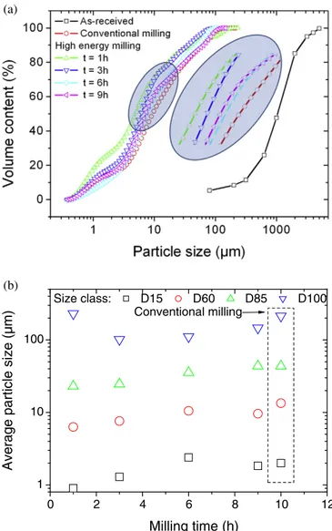
Particle size distribution analysis of GBFS is presented inFig. 3for all milling conditions.Fig. 3a exhibits the main modifications occurring on the particle size profiles depending on milling type and duration. All particle size distributions are plotted in cumulative form. Due to the large-size particles composing the as-received slag powder, granulometry is determined using classical sieving method. The median size value D50 of the as-received slag is close to 1.1 mm. Granulometry of 85% of the distribution is below a size of 2 mm. If laser diffraction is used to obtain the initial particle size of the as-received slag, this leads certainly to underestimation of the outcome of the milling process on particle size reduction. Salman et al.[27]used laser granulometry to characterize the size dispersion of stainless steel refining slag. They achieve a median value of 45μm and point out the limit of the technique to appropriately address shape effects. The reading of their SEM micrograph shows also possible underestimation of the starting granulometry.
In the present study, a size shift of about two orders of magnitude appears as a result of milling (Fig. 3a). Granulometry achieved using conventional milling is close to the one obtained at larger high energy milling durations (tN 3 h). However, the kinetics of particle size shrink-age related to high energy milling shows that milling types are far from being equivalent. Indeed, significant particle size reduction is achieved after the completion of thefirst hour of high energy milling. The further increase in particle size for larger times (tN 1 h) demonstrates an evi-dence of particle agglomeration. This kinetics is further described later
using SEM images. Quantitative analysis of size class trends as function of milling time shows the following (Fig. 3b). Evidence of agglomeration is supported by the D15 size class. Fine particles (D15) shows a steep in-crease in size up to 6 h of high energy milling with an average size of 2.5μm reached at t = 6 h. The D15 trend surpasses the achieved particle size using conventional milling. However, the analysis of thefinal mill-ing duration shows that there is some transfer to the upper class (D60), which results in a smaller particle size. The same trend is noticed for D60 but with a smaller rate. Here, the transfer to upper classes due to agglomeration is limited compared to the previous case. The largest D60 value remains smaller compared to the average size achieved by conventional milling. The same trend is noticed for D85 with a slower rate of particle size increase with respect to milling duration. Finally, the D100 trend is characterized by a strong competition between parti-cle fracturing and agglomeration. In particular, partiparti-cle shrinkage con-tinues up to an optimal milling time of 3 h. The monotonous positive trend noticed for tN 3 h translates the upper hand of agglomeration over particle shrinkage.
In order to keep going on fracturing of small particles (b30 μm), 1 h or less of high energy milling is optimal. Fracturing of larger particles can be considered up to 3 h but a cost of accepting agglomeration of smaller ones. Kumar et al.[30]considered attrition milling of slag up to 1 h. The authors show a continuous shift of particle size distribution
Table 2
Assignments of FT-IR peaks corresponding to the as-received slag. Wave number (cm−1) Assignment
662 Si\\O\\Si bending vibration modes 713 Ca\\O stretching band
874, 1004 Si\\O stretching band
1419 O\\C\\O asymmetric stretching vibration bonds 2017, 2160 H\\O\\H stretching
2312 C\\O stretching vibration 3667, 3814, 3851 OH groups
0
2
4
6
8
10
12
1
10
100
Average particle size (µm)
Milling time (h)
Size class:
D15
D60
D85
D100
Conventional milling
(b)
(a)
Fig. 3. (a) Particle size cumulative distribution as function of milling conditions. (b) Analysis of average particle size versus milling time for different particle size classes.
of slag towards small classes with a median value reaching 3.7μm at the final milling time.
Results of slag milling reported by Kriskova et al.[29]show no evi-dence of agglomeration for large milling durations (between 2 and 6 h). With regards to the achieved specific surface area in their results, bead milling used in their study can be considered as intensive. This re-sult contrasts with the present study. The main difference between their results and ours may be explained by the presence of process control agents (ethanol), which is supposed to enhance fracturing phenomenon.
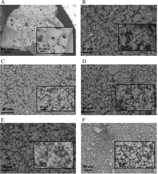
Fig. 4shows the evolution of GBFS morphology as function of milling
duration. The as-received slag exhibits an airy irregular shape with a smooth surface. Although, it is difficult to measure characteristic dimen-sions from SEM, the surface density of porosities seems to be close to 4%
(Fig. 4a). The porosity size varies between 3 and 88μm with an average
size of 10μm. Result of conventional milling (Fig. 4b) shows significant particle size dispersion. In addition, particle morphology modification is evident upon milling. Larger particles maintain, to some extent, the ir-regular shape, whereas smaller ones appear more globular and sticky. The shape factor (i.e., ratio between the smallest and largest intercept length) is 0.51 ± 0.07 for large particles. The same structural attribute measured for small particles is close to 0.91 ± 0.17. No evidence of po-rosity is found within both small and large particles. The observed change in morphology reflects the result of repeated welding, fractur-ing, and rewilding of particles[40]. High-energy milling performed for
1 h (Fig. 4c) leads to the same particle size reduction observed for con-ventional milling but differences in particle morphology and degree of finesse are striking. We observe a denser and homogeneous population offine particles that decorate larger ones. The smaller particles tend to weld together and the larger particles to fracture. Further increase of high energy milling (Fig. 4c–f) accentuates particle rewelding to such a state where the milled powder appears as a connected cohesive net-work. The development of the particle network can be explained by an increase of the local temperature, which enhances cohesive forces between aggregates[41].
The balance between fracturing and welding seems to be achieved within thefirst hour of milling (Fig. 4c) as no evident of reduction in size of large particle is perceived for larger milling times. Wan et al.
[28]confirm morphological changes from irregular to spherical shapes through SEM observations of milled slag. The authors claim also the pos-sibility to control better the particle size dispersity using airflow mill and show different outcomes depending on the type of milling process. To better capture the outcome of the present milling process, specific surface area results are exposed inFig. 5. The specific surface area of the as-received slag is 0.29 m2/g. Most reported results in the literature
places specific surface area levels for GBFS between 0.37 m2/g and
0.48 m2/g[2]. Conventional milling increases specific surface area by 38%. This is a much lesser extent than the result of thefirst hour of high energy milling (434%). In addition, the increase of specific surface area reaches its maximum value (1.8 m2/g) after 3 h of high-energy
Fig. 4. SEM micrographs showing the evolution of slag particle morphology from the (a) as-received to the (b) conventional and (c) high energy milling for milling time (t) of (c) 1 h, (d) 3 h, (e) 6 h and (f) 9 h.
milling. The decreasing branch observed for longer milling time con-firms the tendency of agglomeration. This result is supported by the analysis of granulometry (Fig. 3), and more particularly the trend exhib-ited by the D100 size class (Fig. 3b).
Reported results on specific surface area evolution as function of milling are numerous. Wan et al.[28]have found a lower range of spe-cific surface area values between 0.51 m2/g and 0.685 m2/g for different
milling processes. Kriskova et al.[29]have found higher levels of specific surface area in the range (0.7 m2/g–9.7 m2/g) after 6 h of milling.
3.2. Workability of cement-slag pastes
Slag cement pastes prepared using 45% of slag in substitution result in the workability tendencies shown inFig. 6. One can read the similar-ity between consistency scores and specific surface area results shown
inFig. 5. The reference CEM I paste exhibits the lowest consistency
score (ε). The use of conventional milling has an unperceivable effect on cement paste consistency. One hour of high energy is sufficient to in-crease the consistency of the slag cement paste by 43% to its maximum level. A more stable steady-state consistency is observed for longer mill-ing times. These observations match the workability tendencies report-ed on cementitious materials modified using slag[2,3,28,42]. For instance, the same positive correlation between workability and specific
surface area is pointed out by Wan et al.[32]. In addition, Nath and Sarker.[42]noticed that the slump of concrete andflow of mortar de-creased with the increase of slag content in the mixtures.
3.3. Structural and thermal behavior of slag cement paste
X-ray diffraction patterns of slag cement pastes performed are shown inFig. 7for all milling conditions. These patterns are informative of hydration reaction for hardened paste at 120 curing days. The refer-ence paste cement CEM I contains calcium hydroxide (portlandite) Ca(OH)2 of a hexagonal structure characterized by different plan
peaks P(001), P(100), P(101), P(102), P(110), P(111), P(201), P(112). We have also evidence of calcium carbonate (calcite) CaCO3presence
with rhombohedral structure characterized by different plan peaks C(104), C(113), C(202). In addition, calcium silicate hydrate (C\\S\\H) is detected with Ca2SiO43H2O monoclinic structure identified by S(100),
S(112), S(016), S(-507), S(-321), S(-122) and also ettringite with Ca6Al2(SO4)3(OH)1226H2O hexagonal structure identified by E(101),
E(220), E(304), E(322) and E(332). Former studies indicate that CSH gel is generally identified as an amorphous structure[43,44] and Ettreingite is detectible after long curing time[45]. Paste cement CEM I modified by 45% of slag milled using conventional route exhibits the same collection of peaks of nearly the same intensities. In addition, the presence of peak S1(211) is attributed to a second C\\S\\H with
Ca2SiO4H2O orthorhombic structure. Other characteristic peaks
A(102), A(522), A(260) are informative of the presence of C\\A\\H with Ca2(AlO2)3(OH)(H2O) orthorhombic structure.
Modified cement pastes with high energy milled slag shows evi-dence of C\\S\\H peak S1(211) irrespective of milling duration (Fig.
7). The remarkable effect of high energy milling can be attributed to the decreasing intensity, enlargement and slight shift of portlandite peaks. The decaying portalandite peaks can be attributed to pozzolanic reactions between activated slag and calcium hydroxide. The hydration
0 2 4 6 8 10 0.0 0.4 0.8 1.2 1.6 2.0
High energy milling
Specific surface area (m²/g)
Milling time (h)
Conventional milling
Fig. 5. Specific surface area of GGBFS for both conventional and high energy milling.
0
2
4
6
8
10
12
65
70
75
80
85
90
95
100
105
Flow test
ε
(%)
Milling time (h)
High energy milling
Conventional milling
process of Portland cement can be summarized as follows[46,47]: C2Sþ 2H→0:5C3S2H3þ 0:5CH ð1Þ
C3Sþ 3H→0:5C3S2H3þ 1:5CH ð2Þ
whereas the pozzolanic reaction can be summarized asflows[48,49]: Sþ 1:5 CH→0:5C3S2H3 ð3Þ
Aþ 4CH þ 9H→C4AH13 ð4Þ
where C: CaO, S: SiO2, A: Al2O3, H: H2O, CH: Ca(OH)2.
As observed from theexpressions (3) and (4), the active silica (SiO2)
and aluminate (Al2O3) of milled slag react with calcium hydroxide
orig-inated from Portland cement hydration giving raise to calcium silicate hydrate, i.e., C\\S\\H like inexpression (3)or calcium aluminate hy-drate, i.e., C\\A\\H like inexpression (4). Shi and Day[50]have studied the products of pozzolanic reaction mechanisms in lime + pozzolan ce-ment pastes in the presence of Na2SO4and CaCl2. Their X-ray diffraction
(XRD) analysis pointed out the large and sharp diffuse band of calcium silicate hydrate (C\\S\\H) with curing time and the vanishing trend of Ca(OH)2after 180 days. We believe that, in our case, the boarding and
slight shift of portlandite peaks can be attributed to the reduction of crystallite size and inter-reticular distance of portlandite, respectively
[36].
Fig. 8shows the evolution of lattice parameter (a, c), cell volume
(V = a × a × c) and crystallite size of portlandite for all studied formu-lations. The lattice parameters (a) and (c) of portlandite structure given by ICDDfile are a = 0.3590 nm and c = 0.4916 nm, respectively. The same parameters determined from the reading of XRD results show slight changes with a = 0.3604 ± 0.0005 nm and c = 0.4942 ± 0.0005 nm. The lattice parameter (a) decreases with the increase of high energy milling time up to 3 h before stabilization. This result con-trasts with the effect of conventional milling, where negligible variation of lattice parameter (a) is observed. The lattice parameter (c) follows the opposite trend versus milling time with the same stabilization after 3 h of high energy milling. Here also, the effect of conventional milling is minor. The evolution of the cell (V) and the crystallite size (D) confirm the critical effect of the three first hours of high energy mill-ing, more particularly for the crystallite size, D. Indeed, the crystallite size decreases from its reference condition (D = 79.4 ± 2.5 nm) to its steady-state value (D = 17 ± 1.5 nm), which represents about 79% as an amount of variation. In contrast to this, conventional milling has no particular effect on both crystallite size and cell volume.
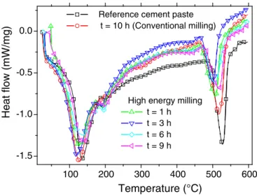
Fig. 9shows DSC results of slag cement pastes for all formulations
in-volving slag milling time. Heatflow curves show the existence of some endothermic peaks attributed to the decomposition of water bonding in
two particular regions. Thefirst region of decomposition is bounded be-tween 100 °C and 350 °C. It is a characteristic of adsorbed water and it may be related to decomposition of ettringite, dehydration of calcium-silicate hydrate (C\\S\\H) gel and calcium-aluminate hydrate. This statement is based on identified phases from the XRD analysis (Fig. 8). The second stage of decomposition is in the range of 400 °C and 550 °C. This region is characteristic of crystalized water and corresponds to the decomposition of Ca(OH)2. The confrontation of these
observa-tions with the concerned literature show that the range between 50 °C and 300 °C is generally attributed to decomposition of ettringite, C\\S\\H, C\\A\\H and monosulfoaluminate, whereas the range from 400 °C to 500 °C is attributed to decomposition of calcium hydroxide
[51–55].
To follow the enthalpy change (ΔH) associated with the decomposi-tion of both adsorbed and crystalized water, an estimate on the areas under the endothermic peaks in the temperature range (100 °C– 250 °C) and (400 °C to 550 °C) is provided.Table 3summarizes (ΔH) values as function of milling time. For cement paste formulations in-volving high energy milling (0b t b 10 h), we observe that ΔH associat-ed to the decomposition of crystallizassociat-ed water follows a two-stage evolution with afirst increasing stage up to 3 h and then a steady-state value. The decreasing tendency ofΔH associated to crystallized water can be related to the pozzolanic reactions between milled slag and calcium hydroxide. This explanation is supported by DRX results. The former trend is not ultimately observed forΔH associated to absorbed water. In this case, a slight increase after 3 h of high energy milling can be attributed to secondary C\\S\\H formation from pozzo-lanic reactions between milled slag and Ca(OH)2. Undetectable changes
in bothΔH values associated to crystallized and absorbed waters for those cement paste formulations involving slag milling using conven-tional route. 0 2 4 6 8 10 12 0.36 0.40 0.44 0.48 0.52 0.56 0.60 0.64 a c V D
Milling time (h)
a, c (nm), V (x10
-1nm
3)
Conventional milling
0 10 20 30 40 50 60 70 80Crystallite size D (nm)
Fig. 8. Evolution of the lattice parameters (a), (c), cell volume (V) and crystallite size (D) of portlandite as function of milling time for both conventional and high energy milling.
100
200
300
400
500
600
-1.5
-1.0
-0.5
0.0
High energy milling t = 1 h t = 3 h t = 6 h t = 9 h
Heat flow (mW/mg)
Temperature (°C)
Reference cement paste t = 10 h (Conventional milling)
Fig. 9. DSC curves of slag cement pastes as function of milling time.
Table 3
Enthalpy change (ΔH) of both adsorbed and crystalized water for all slag cement paste for-mulations as function of slag milling time.
Milling time, t (h) ΔH adsorbed water (J/g) ΔH crystalized water (J/g)
0 80.5 ± 2 115.2 ± 3 10a 79.4 ± 1.7 104.5 ± 3 1 76.1 ± 2.1 68.7 ± 2.8 3 87.1 ± 2.4 55.7 ± 2.5 6 86.1 ± 1.8 54.8 ± 2.7 9 82.1 ± 1.7 56.5 ± 2.8 a Conventional milling.
3.4. Mechanical behavior of cement-slag pastes
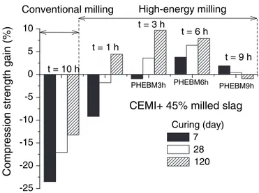
Fig. 10shows the compression strength gain for slag paste cements
for all milling conditions as function of slag milling time. The gain is measured with respect to the reference paste, which exhibits compres-sive strength of 52, 55 and 57 MPa after 7, 28 and 120 curing days.
Table 4summarizes the magnitude of compressive strengths for all
attempted formulations. We observe a negative effect on compression strength for all curing days when conventional milling of slag is used in the formulation of cement pastes. The best situation corresponds to a strength loss of−14% after 120 of curing days. An overall evaluation of the effect of high energy milling of slag shows a beneficial role on compressive strength of cement pastes. The optimal situation corre-sponds to 3 h of milling, which results in the largest gain (8.8%) in strength after 120 curing days. This represents a compressive strength of 62 MPa.
4. Conclusions
High energy milling proves to be an effective way to achieve high rates of slagfinesse. High energy milling efficiency is limited by the ag-glomeration of slag particles, which is observed for milling durations su-perior to 3 h. This study concludes that the most relevant milling durations are within the hour unit. The decrease of the crystallite size of portlandite seems to be related to the efficiency of high energy mill-ing within thefirst 3 h of the process. In contrast, such behavior is not observed for conventional milling. Mechanical activation of slag in ce-ment paste is demonstrated through the presence of C\\S\\H and the decaying profile of portlandite. High energy milling has a direct effect on the pozzolanic reactions that take place in the slag cement paste.
Mechanical results provide an insight on the substitution of cement by milled slag. Improvement of both short and long term compressive strength of slag cement paste is possible with formulations involving 45% of cement CEM I substitution with high energy milled slag. Acknowledgments and funding information
We thank Margarita Walferdein from IRC/ESTP, Cachan, France, for her technical assistance concerning structure and mechanical measurements.
References
[1] F. Bellmann, J. Stark, Activation of blast furnace slag by a new method, Cem. Concr. Res. 39 (2009) 644–650.
[2] R. Siddique, Waste Materials and By-products in Concrete, Springer-Verlag, Berlin Heidelberg, 2008.
[3] E. Ozbay, M. Erdemir, H.I. Durmus, Utilization and efficiency of ground granulated blast furnace slag on concrete properties - a review, Constr. Build. Mater. 105 (2016) 423–434.
[4] K.H. Mo, U.J. Alengaram, M.Z. Jumaat, Utilization of ground granulated blast furnace slag as partial cement replacement in lightweight oil palm shell concrete, Mater. Struct. 48 (2015) 2545–2556.
[5] B.S. Divsholi, T.Y.D. Lim, S. Teng, Durability properties and microstructure of ground granulated blast furnace slag cement concrete, Int. J. Concr. Struct. Mater. 8 (2014) 157–164.
[6] O. Ekincioglu, A.P. Gurgun, Y. Engin, M. Tarhan, S. Kumbaracibasi, Approaches for sustainable cement production - a case study from Turkey, Energ. Buildings 66 (2013) 136–142.
[7] K. Yanagisawa, Z. Matamoros-Veloza, J.C. Rendon-Angeles, J. Lopez-Cuevas, Novel route for recycling of steelmaking slag by means of the hydrothermal hot-pressing method, J. Mater. Sci. Lett. 21 (2002) 693–695.
[8] H. Hilbig, A. Buchwald, The effect of activator concentration on reaction degree and structure formation of alkali-activated ground granulated blast furnace slag, J. Mater. Sci. 41 (2006) 6488–6491.
[9] Y.J. Zhang, Y.L. Zhao, H.H. Li, D.L. Xu, Structure characterization of hydration prod-ucts generated by alkaline activation of granulated blast furnace slag, J. Mater. Sci. 43 (2008) 7141–7147.
[10] M.C.G. Juenger, P.J.M. Monteiro, E.M. Gartner, In situ imaging of ground granulated blast furnace slag hydration, J. Mater. Sci. 41 (2006) 7074–7081.
[11]A. Jelidi, S. Bouslama, Use effects of blast furnace slag aggregates in hydraulic con-crete, Mater. Struct. 48 (2015) 3627–3633.
[12] Y.L. Yue, X.H. Zhang, Y.C. Xu, S.X. Huang, P.P. Chen, Structural, dielectric and melting properties of aluminosilicate glasses based on blast furnace slag for printed circuit board applications, Mater. Lett. 136 (2014) 356–358.
[13]S. Dimitrova, V. Nikolov, D. Mehandjiev, Effect of the heat treatment on the mor-phology and sorption ability to metal ions of metallurgical slag, J. Mater. Sci. 36 (2001) 2639–2643.
[14] J.V. Dubrawski, Thermal characteristics of aged granulated blast furnace slags, J. Therm. Anal. 48 (1997) 63–72.
[15]E. standards, Ground granulated blast furnace slag for use in concrete, mortar and grout, Definitions, Specifications and Conformity Criteria, Europ. standards, 2006.
[16] X.L. Guo, H.S. Shi, Modification of steel slag powder by mineral admixture and chemical activators to utilize in cement-based materials, Mater. Struct. 46 (2013) 1265–1273.
[17]Y. Li, W. Guo, H. Li, Quantitative analysis on ground blast furnace slag behavior in hardened cement pastes based on backscattered electron imaging and image anal-ysis technology, Constr. Build. Mater. 110 (2016) 48–53.
[18]X. Huang, Z. Wang, Y. Liu, W. Hu, W. Ni, On the use of blast furnace slag and steel slag in the preparation of green artificial reef concrete, Constr. Build. Mater. 112 (2016) 241–246.
[19] L.J. Gardner, S.A. Bernal, S.A. Walling, C.L. Corkhill, J.L. Provis, N.C. Hyatt, Characteri-sation of magnesium potassium phosphate cements blended withfly ash and ground granulated blast furnace slag, Cem. Concr. Res. 74 (2015) 78–87.
[20]H. El-Didamony, M.S. Mohammed, R.M. Osman, Effect of substitution of blast-fur-nace slag byfired drinking water sludge on the properties of pozzolanic cement pastes, J. Therm. Anal. Calorim. 122 (2015) 81–88.
[21] V. Dodson, Concrete Admixtures, Springer Science & Business Media, 2013.
[22] J. Abdo, Ciment (in French), Techniques de l'ingénieur, 2008 C920.
[23]E. standards, Cement - Part 1: Composition, Specifications and Conformity Criteria for Common Cements, Europ. standards, 2000.
[24]H.E.H. Seleem, A.M. Rashad, B.A. El-Sabbagh, Durability and strength evaluation of high-performance concrete in marine structures, Constr. Build. Mater. 24 (2010) 878–884.
[25] E. standards, Methods of testing cement - part 1: determination of strength, Europ. Standards, 2005.
[26]A.F. Abdalqader, F. Jin, A. Al-Tabbaa, Development of greener alkali-activated ce-ment: utilisation of sodium carbonate for activating slag andfly ash mixtures, J. Clean. Prod. 113 (2016) 66–75.
[27] M. Salman, O. Cizer, Y. Pontikes, R. Snellings, L. Vandewalle, B. Blanpain, K. Van Balen, Cementitious binders from activated stainless steel refining slag and the ef-fect of alkali solutions, J. Hazard. Mater. 286 (2015) 211–219.
-25
-20
-15
-10
-5
0
5
10
High-energy milling
t = 9 h
t = 6 h
t = 3 h
t = 1 h
Curing (day)
7
28
120
Compression strength gain (%)
CEMI+ 45% milled slag
t = 10 h
PHEBM3h PHEBM6h PHEBM9h
Conventional milling
Fig. 10. Compression strength gain of slag cement pastes as function of milling time.
Table 4
Compression strength of slag cement pastes as function of milling and curing conditions. Formulation Slag milling time
(h)
Compressive strength (MPa) Curing, 7 days Curing, 28 days Curing, 120 days CEMI000b No slag 52 55 57 PCOM10H 10a 40 46 49 PHEBM1H 1 47 54 60 PHEBM3H 3 52 57 63 PHEBM6H 6 54 59 62 PHEBM9H 9 53 55 56 a Conventional milling. b Reference.
[28] H.W. Wan, Z.H. Shui, Z.S. Lin, Analysis of geometric characteristics of GGBS particles and their influences on cement properties, Cem. Concr. Res. 34 (2004) 133–137.
[29] L. Kriskova, Y. Pontikes, O. Cizer, G. Mertens, W. Veulemans, D. Geysen, P.T. Jones, L. Vandewalle, K. Van Balen, B. Blanpain, Effect of mechanical activation on the hy-draulic properties of stainless steel slags, Cem. Concr. Res. 42 (2012) 778–788.
[30] R. Kumar, S. Kumar, S. Badjena, S.P. Mehrotra, Hydration of mechanically activated granulated blast furnace slag, Metall. Mater. Trans. B Process Metall. Mater. Process. Sci. 36 (2005) 873–883.
[31]A. Allahverdi, M. Mahinroosta, Mechanical activation of chemically activated high phosphorous slag content cement, Powder Technol. 245 (2013) 182–188.
[32]A. Bougara, C. Lynsdale, K. Ezziane, Activation of Algerian slag in mortars, Constr. Build. Mater. 23 (2009) 542–547.
[33] M. Behim, M. Cyr, P. Clastres, Physical and chemical effects of El Hadjar slag used as an additive in cement-based materials, Eur. J. Environ. Civ. Eng. 15 (2011) 1413–1432.
[34] R. Hamzaoui, O. Elkedim, E. Gaffet, Friction mode and shock mode effect on magnet-ic properties of mechanmagnet-ically alloyed Fe-based nanocrystalline materials, J. Mater. Sci. 39 (2004) 5139–5142.
[35]G.K. Williamson, W.H. Hall, X-ray line broadening fromfiled aluminium and wol-fram, Acta Metall. 1 (1953) 22–31.
[36] R. Hamzaoui, O. Bouchenafa, S. Guessasma, N. Leklou, A. Bouaziz, The sequel of mod-ified fly ashes using high energy ball milling on mechanical performance of substituted past cement, Mater. Des. 90 (2016) 29–37.
[37] N. Afnor, In french: Méthodes d'essai des mortiers pour maçonnerie - Partie 3: de-termination de la consistance du mortier frais (avec une table à secousses), Europ. standards, 1999 12–303.
[38] M. Thomas, Supplementary Cementing Materials in Concrete, CRC Press, 2013.
[39] E. Gaffet, G. Le Caër, Mechanical processing for nanomaterials, in: H.S. Nalwa (Ed.), Encyclopedia of Nanoscience and Nanotechnology, American Scientific Publishers 2004, pp. 91–129.
[40] R. Hamzaoui, O. Elkedim, E. Gaffet, Milling conditions effect on structure and mag-netic properties of mechanically alloyed Fe-10% Ni and Fe-20% Ni alloys, Mater. Sci. Eng. A-Struct. 381 (2004) 363–371.
[41] S. Tria, O. Elkedim, R. Hamzaoui, X. Guo, F. Bernard, N. Millot, O. Rapaud, Deposition and characterization of cold sprayed nanocrystalline NiTi, Powder Technol. 210 (2011) 181–188.
[42] P. Nath, P.K. Sarker, Effect of GGBFS on setting, workability and early strength prop-erties offly ash geopolymer concrete cured in ambient condition, Constr. Build. Mater. 66 (2014) 163–171.
[43] P. Barnes, J. Bensted, Structure and Performance of Cements, second ed. CRC Press, 2011.
[44] K.K. Aligizaki, Pore Structure of Cement-Based Materials: Testing, Interpretation and Requirements, CRC Press, 2005.
[45]R. Taylor, I.G. Richardson, R.M.D. Brydson, Composition and microstructure of 20-year-old ordinary Portland cement-ground granulated blast-furnace slag blends containing 0 to 100% slag, Cem. Concr. Res. 40 (2010) 971–983.
[46] V.G. Papadakis, Effect offly ash on Portland cement systems part I. Low-calcium fly ash, Cem. Concr. Res. 29 (1999) 1727–1736.
[47] E.G. Nawy, Concrete Construction Engineering Handbook, CRC Press, 2008.
[48] V.G. Papadakis, Development of high durability of concrete by using cement Portland based benders, in: R.K. Dhir, M.J. McCarthy (Eds.),Concrete Durability and Repair Technology: Proceedings of the International Conference Held at the University of Dundee, Scotland, Thomas Telford 1999, p. 103.
[49]Q. Zeng, K.F. Li, T. Fen-chong, P. Dangla, Determination of cement hydration and pozzolanic reaction extents forfly-ash cement pastes, Constr. Build. Mater. 27 (2012) 560–569.
[50]C.J. Shi, R.L. Day, Pozzolanic reaction in the presence of chemical activators part II. Reaction products and mechanism, Cem. Concr. Res. 30 (2000) 607–613.
[51]A. Rungchet, P. Chindaprasirt, S. Wansom, K. Pimraksa, Hydrothermal synthesis of calcium sulfoaluminateebelite cement from industrial waste materials, J. Clean. Prod. 115 (2016) 273–283.
[52]M.E.I. Saraya, Study physico-chemical properties of blended cements containing fixed amount of silica fume, blast furnace slag, basalt and limestone, a comparative study, Constr. Build. Mater. 72 (2014) 104–112.
[53] S. Kumar, R. Kumar, A. Bandopadhyay, T.C. Alex, B.R. Kumar, S.K. Das, S.P. Mehrotra, Mechanical activation of granulated blast furnace slag and its effect on the proper-ties and structure of Portland slag cement, Cem. Concr. Compos. 30 (2008) 679–685.
[54] B.W. Jo, S. Chakraborty, Y.S. Lee, Hydration study of the polymer modified jute fibre reinforced cement paste using analytical techniques, Constr. Build. Mater. 101 (2015) 166–173.
[55] Y.F. Fan, S.Y. Zhang, Q. Wang, S.P. Shah, The effects of nano-calcined kaolinite clay on cement mortar exposed to acid deposits, Constr. Build. Mater. 102 (2016) 486–495.