Heat exposure measurements in fire resistance wall and floor test furnaces
Texte intégral
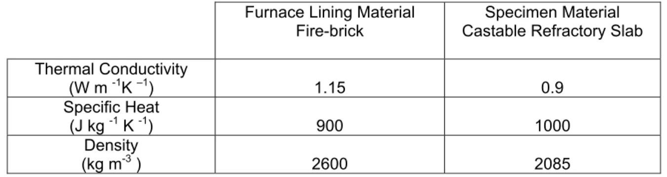
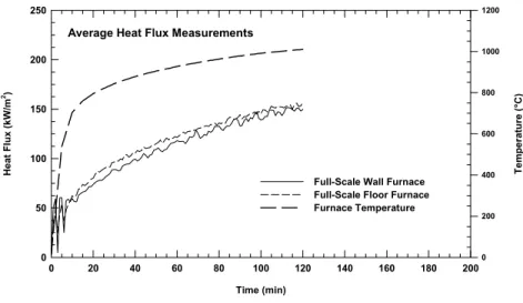
Figure


Documents relatifs
transcriptomic data suggest that (i) most of the genes required for canonical land plant-like retrograde signaling were already present in ZCC-grade streptophyte algae (Nishiyama
The aims of the study were to estimate genetic parameters, to identify quantitative trait loci (QTL) and to assess the ef- ficiency of genomic selection (GS) compared to
47 California State University, Fresno, California 93740, USA.. 48 University of California, Riverside, California
his was particularly important for the GABRA1−/− larvae as it brought the concentrations of THC and CBD required to oppose the seizure activity to levels that had much less of
To establish a facility (for storing and validating data, retrieving data, interpreting and analyzing data, and constructing and applying models using those data),
Goat value chain in Algeria, sustainable development proposals to cope with changes.. Hossem Sahraoui, Fateh Mamine,
4 School of Physics State Key Laboratory of Nuclear Physics and Technology, Peking University,
This new combined diet (CD) comprises medium-chain fatty acids, polyunsaturated fatty acid, low glycaemic index carbohydrates, and a high BCAA/AAA ratio.. We first ascertained
