HAL Id: hal-01757907
https://hal.archives-ouvertes.fr/hal-01757907
Submitted on 4 Apr 2018
HAL is a multi-disciplinary open access
archive for the deposit and dissemination of
sci-entific research documents, whether they are
pub-lished or not. The documents may come from
teaching and research institutions in France or
abroad, or from public or private research centers.
L’archive ouverte pluridisciplinaire HAL, est
destinée au dépôt et à la diffusion de documents
scientifiques de niveau recherche, publiés ou non,
émanant des établissements d’enseignement et de
recherche français ou étrangers, des laboratoires
publics ou privés.
Gravity Compensators
Alexandr Klimchik, Anatol Pashkevich, Stéphane Caro, Benoît Furet
To cite this version:
Alexandr Klimchik, Anatol Pashkevich, Stéphane Caro, Benoît Furet. Calibration of Industrial Robots
with Pneumatic Gravity Compensators. 2017 IEEE International Conference on Advanced Intelligent
Mechatronics (AIM), Jul 2017, Munich, Germany. �10.1109/AIM.2017.8014031�. �hal-01757907�
Equation Chapter 1 Section 1
Abstract— The paper is devoted to the stiffness modeling of
heavy industrial robots with pneumatic gravity compensators. The main attention is paid to the identification of elastostatic parameters and calibration accuracy. To reduce impact of the measurement errors, the set of manipulator configurations for calibration experiments is optimized with respect to the pro-posed performance measure related to the end-effector position accuracy. Advantages of the developed technique are illustrated by dedicated experimental study.
Keywords— Industrial robot, stiffness modeling, elastostatic
calibration, pneumatic gravity compensator, design of calibra-tion experiments.
I. INTRODUCTION
Advancements in shipbuilding and aeronautic industries demand high-precision and high-speed machining of huge hulls and fuselage components. For these tasks, industrial ro-bots are more attractive comparing to conventional CNC-machines because of large and easily extendable workspace, capability to process complex-shape parts and high-speed motion capability. However, processing of modern and con-temporary materials, which are widely used in these indus-tries, requires high processing forces affecting robot posi-tioning accuracy [1-3]. To reduce the external force impact on the positioning accuracy, robotic experts usually apply technique that is based on the compliance error estimation via the manipulator stiffness modelling [4-7] and relevant er-ror compensation in the online or offline mode [8-11]. This approach is very efficient if the stiffness and geometric mod-el parameters of the manipulator as wmod-ell as the external forc-es are known. To forc-estimate them, additional experimental studies are usually carried out [4, 12-14], which allow user to obtain an extended geometric model suitable for compliance error compensation.
Another practical solution is based on enhancement the robot stiffness by means of increasing the link cross-sections. However, it leads to increasing of the robot components masses causing additional end-effector deflections, which are usually reduced by means of different types of gravity
com-*The work presented in this paper was partially funded by Innopolis University and the project Partenariat Hubert Curien SIAM 2016 France-Thailand
A. Klimchik is with Innopolis University, Universitet-skaya St, 1,
Inno-polis, 420500, Russia (e-mail: [email protected]).
A. Pashkevich is with IMT Atlantique, 4 rue Alfred-Kastler, Nantes 44307, France and with Institut LS2N (e-mail: [email protected]).
S. Caro is with Centre National de la Recherche Scientifique (CNRS), France (email: [email protected])
B. Furet are with University of Nantes, France (e-mails: [email protected], [email protected]).
pensators. However, integration of mechanical compensators into manipulator kinematics essentially complicates the stiff-ness modelling, because conventional serial architecture is transformed into the quasi-serial one that contains a kinemat-ic closed loop.
The stiffness modelling of the industrial manipulators with mechanical gravity compensators is quite a new problem. There are rather limited number of works dealing with the impact of gravity compensators on the manipulator force-deflection relation [13, 15, 16], while there are some work devoted to the compensator design [17, 18] and software-based balancing solutions [19, 20]. In contrast, for conven-tional strictly serial manipulators [6, 21, 22] and strictly par-allel mechanisms [7, 23-27] there were developed a number of methods for the stiffness analysis. At the same time, only limited number of works deals with stiffness modelling of so-called quasi-serial architectures incorporating internal closed-loops [15, 28-31]. To our knowledge, the simplest and efficient way to take into account the influence of gravity compensator is utilization of non-linear virtual springs in the frame of the conventional VJM technique [7, 32, 33]. This approach was originally proposed in our previous works [15, 16] and successfully applied to the manipulators the spring-based gravity compensators. However, some additional ef-forts are required to adapt it to the case of robots with pneu-matic compensators, which progressively replace their coun-terparts in new models of heavy industrial robots available on the market.
This paper proposes a new modification of the VJM-based stiffness modelling technique for the quasi-serial in-dustrial manipulators with a pneumatic gravity compensator that creates a kinematic closed-loop violating the stiffness modelling principles, which are used for pure serial robot ar-chitecture. The main attention is paid to the identification of the model parameters and calibration experiment planning. The developed approach is confirmed by the experimental results that deal with compliance error compensation for ro-botic cell employed in manufacturing of large dimensional components.
To address these problems the remainder of the paper is organized as follows. Section 2 presents the stiffness model-ling for pneumatic gravity compensator. Section 3 is devoted to the elastostatic calibration and design of calibration exper-iments. Section 4 deals with experimental study. Section 5 summarizes the main contributions of the paper.
Calibration of industrial robots
with pneumatic gravity compensators
A. Klimchik, IEEE Member, A. Pashkevich, S. Caro and B. Furet
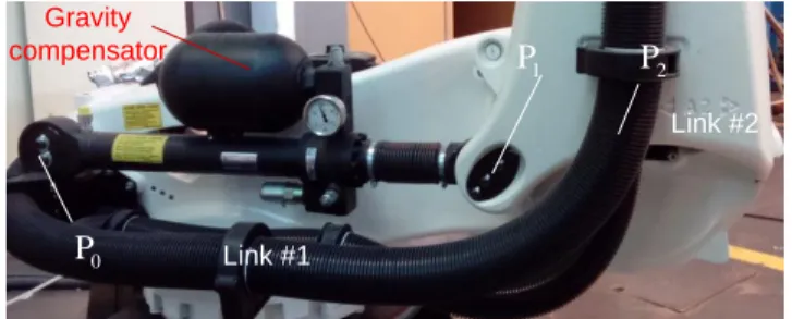
II. MECHANICS OF PNEUMATIC GRAVITY COMPENSATOR The mechanical structure and principal components of pneumatic gravity compensator considered here is presented in Fig. 1a; its equivalent model is shown in Fig. 1b. The me-chanical compensator is a passive mechanism incorporating a constant cross-section cylinder and a constant volume gas reservoir. The volume occupied by the gas linearly depends on the piston position that defines the internal pressure of the cylinder. It is clear that this mechanism can be treated as a non-linear virtual spring influencing on the manipulator stiff-ness behavior. It is worth mentioning that in general case the gas temperature has impact on the pressure inside the tank, which defines the compensating force. Nevertheless, one can assume that in the case of continuous or periodical manipula-tor movements the gas temperature remains almost constant, i.e. the process of the gas compression-decompression can be assumed to be the isothermal one.
x a y a 2 q s L Link 2 0 P 2 P 1 P Link 1 a c k 2 q k s F c F l F O (a) Pneumatic gravity compensator of robot KUKA KR-210 TM
(b) model of gravity compensator 0 P 2 P 1 P Gravity compensator Link #1 Link #2
Figure 1. Pneumatic gravity compensator and its mode In the frame of the manipulator model, the compensator is attached to the first and second links that creates a closed-loop acting on the second actuated joint. This particularity allows us to adapt the conventional stiffness model of the se-rial manipulator (with constant joint stiffness matrix Kθ) by introducing the configuration dependent joint stiffness matrix
θ( )
K q that takes into account the compensator impact and depends on the vector of actuated coordinates q. In this case, the Cartesian stiffness matrix KC of the robotic ma-nipulator [22] can be presented in the following form
1 1 T C θ θ ( ) θ K J K q J where J is the Jacobian with respect to the virtual joint co-θ
ordinates θ (in the case of industrial robots it is usually equivalent to the kinematic Jacobian computed with respect to actuated coordinates q). Thus, to obtain the stiffness
model of the industrial robot with the pneumatic gravity compensator it is required to determine the non-linear joint stiffness matrix K qθ( ) describing elasticity of both actuators and the gravity compensation mechanism. It should be men-tioned that in the majority of works devoted to the stiffness analysis of the serial manipulators the matrix Kθ is assumed to be a constant and strictly diagonal one [22, 26, 34].
To find the desired matrix K qθ( ), let us consider the compensator geometry in detail. As follows from Fig 1b, the compensator geometrical model contains three principal node points P0, P1, P2., where P0, P1define the passive joint
rotation axes and P2 defines the second actuated joint axis. In
this model, two distances P P , 1, 2 P P are constants, 0, 2 while the third one P P varies with the robot motions and 0, 1 non-linearly depends on the angle q2. Below, this distances are denoted as follows: L P P1, 2 , a P P1, 2 , s P P0, 1 . In addition, let us introduce parameters ,
, ax and ay defining relevant locations of points P0, P1, P2 (see Fig. 1b).This allows us to compute the compensator length s using the following expression
2 2 2 2 · · ·co 2 s( ) a L s a L q
which defines the non-linear function s q( 2).
For this geometry, the impact of the gravity compensator can be taken into account by replacing the considered quasi-serial architecture by the quasi-serial one, where the second joint stiffness coefficient is modified in order to include elasticity of both the actuator and compensator. To find relevant non-linear expression for this coefficient, let us present the static torque in the second joint M2 as a geometric sum of two components. The first of them is caused by the deflection
2
q
in the mechanical transmission of the second actuated joint and can be expressed in a usual way as
2 2 2 q q M K q , where 2 q
K is the stiffness coefficient. The second compo-nent can be presented as MC FS·Lsin, where FS is the force generated by the gravity compensator. It is clear that
sin can be computed from the triangle P PP0 1 2 using the sines theorem: sin( / ) sin(a s q2). The latter allows us to express the torque M2 in the following form:
2 2 2 q S· ·L sin( 2) a M K q F q s
where both the force FS and the compensator length s de-pend on the joint variable q2 q20q2.
To find the compensating force FS, let us use the iso-thermal process assumption that yields the relation
P V const, where P is the tank pressure,
0 0
( )
V A s s V is the corresponding internal volume, A is the piston area, s0 is compensator link length correspond-ing to zero compensatcorrespond-ing force and V0 is the tank volume corresponding to the atmospheric pressure 5
0 1.01 10
P Pa. These assumptions allow us to express the tank pressure as
0 0 0 0 ( ) P V A s V P s
Taking into account that compensating force FS depends on the internal and external pressure difference and is computed as FS(PP0)A, one can rewrite expression (3) as
2 0 2 0 0 0 2 2 ( ) · · ( ) sin( ) q A s s L A s s V a M K q P q s
and present in a more compact form
2 2 0 2 2 0 s n( ) · i · q V q M q La s s s K P s s
where a constant sV V0/As0 is the equivalent distance.
Further, after computing the partial derivative M2/q2
and using eq. (2) for s/ q2 aL s/ sin(q2), the de-sired aggregated stiffness coefficient is presented in the form
2 2 0 0 2 2 2 2 2 2 0 2 2 sin ( cos( ) sin ( ) ( ) ) ( ) V V q V P L a s s a L q s s s s s s s q a L q K q K s s which is obviously highly non-linear with respect to manipu-lator configuration (here, s is also a non-linear function of
2
q ). Nevertheless, it allows us to compute an relevant stiff-ness coefficient K2 for the equivalent serial chain and direct-ly appdirect-ly eq. (1) to evaluate stiffness of the quasi-serial ma-nipulator with pneumatic gravity compensator.
It should be mentioned that in practice the compensator parameters s0,sV and actuator stiffness coefficients
1, 2, 3,..., 6
K K K K are usually not given in the robot datasheets, so they should be identified via dedicated exper-imental study. For this reason, the following Section focuses on the identification of this extended set of the manipulator elastostatic parameters.
III. ELASTOSTATICPARAMETERSIDENTIFICATION
A. Methodology
In the frame of the VJM-based modelling approach de-veloped for serial kinematic chains [22, 32] and adapted here for the case of quasi-serial manipulators with pneumatic gravity compensators, the desired stiffness model parameters describe elasticity of the virtual springs located in the actuat-ed joints of the manipulator, and also compensator parame-ters s0,sVof defining preloading of the compensator spring and the equivalent distance for the tank volume V0. In the frame of this model, let us denote the manipulator joint com-pliances as , 1,6
j
k j (which are inverse values to the joint stiffness coefficients K K K1, 2, 3,...,K6 used in previous sec-tion) and the compensator elastic parameters as s0,sV.
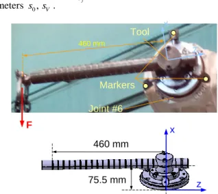
To find the desired set of elastic parameters, the robotic manipulator sequentially passes through several measure-ment configurations where the external loading is applied to the specially designed end-effector presented in Fig. 2 (it al-lows us to generate both forces and torques applied to the manipulator). Using the absolute measurement system (the laser tracker Leica AT900, the Cartesian coordinates of the reference points are measured twice, before and after load-ing. To increase identification accuracy, it is reasonable to have several markers on the end effector (reference points) and to apply the loading of the maximum allowed magnitude. It should be mentioned that to avoid singularities caused by
numerical routines, the external force/torque directions should not be the same for all calibration experiments (while from the practical view point the mass-based gravity loading is the most attractive). Thus, the calibration experiments yield the dataset that includes values of the manipulator joint coordinates
qi , applied forces/torques
F and corre-isponding deflections of the reference points
p . Using i these data, it is required to identify the manipulator elasto-static parameters of , 1,6j
k j and gravity compensator
pa-rameters s0,sV. 75.5 mm 460 mm x z x z 460 mm Joint #6 Tool F Markers
Figure 2. End-effector used for the elastostatic calibration experiments and it model
B. Identification algorithm
To take into account the compensator influence while us-ing classical approach developed for strictly serial manipula-tors without compensamanipula-tors [6], it was proposed below to use in the second joint an equivalent virtual spring with non-linear stiffness, which depends on the joint coordinate q2
(see eq. (1)). Using this idea, it is convenient to consider several aggregated compliances
2 i
k corresponding to each different value of angle q2. This idea allows us to linearize the identification equations with respect to extended set of model parameters and that can be easily solved using stand-ard least-square technique.
Let us denote this extended set of desired parameters as
1, ( 21, 22...), 3,..., 6
k k k k k and collect them in the vector k . In this case the linearize force-deflection relation with respect to this vector can be present in the following form
( )p
i i
p B k
where pi is the vector of the end-effector displacements under the external loading Fi, matrices B( )ip are composed of the elements of the matrix
Ai J J1i 1iTFi,...,J Jni niTFi (i1, )m
that is usually used in stiffness analysis of serial manipula-tors. Here, J denotes the manipulator Jacobian column, ni
superscript '(p)' stands for the Cartesian coordinates (position without orientation). Transformation from Ai to B( )ip is
ra-ther trivial and is based on the extraction from Ai the first three lines and inserting in it several zero columns.
In this case, the elastostatic parameters identification can be reduced to the following optimization problem
0 , , ( ) ( ) 1( ) ( ) min j c m p T p i i i i k k i F
B k p B k p which yields to the following solution 1 ( ) ( ) ( ) 1 1 · T T m m p p p i i i i i i
k B B B p where the parameters k k1, 3,...,k6 describe the compliance of the virtual joints #1,#3,...#6, while the rest of them k21,k22...
present an auxiliary dataset allowing to separate the compli-ance of the joint #2 and the compensator parameters s0,sV. Using eq. (7), the desired optimization problem can be writ-ten as
2 0 2 2 0 0 2 2 2 2 1 2 , 0 2 , ( ) ) ( ) m sin ( cos( ) sin in q V q m i i V i i V i i i s V q K s i P L a s s a L q s s s s s s s q aL q s K s
where m is the number of different angles q q2 in the exper-imental data. It is obvious that eq. (12) is highly non-linear and can be solved numerically only.
Thus, the proposed modification of the previously devel-oped calibration technique allows us to find the manipulator and compensator parameters. An open question, however, is how to find the set of measurement configurations that en-sure the lowest impact of the meaen-surement noise.
C. Design of calibration experiments
The goal of the calibration experiment design is to select a set of robot configurations/external loadings
q F that i, i
ensure the best identification accuracy. The key issue is to rang plans of experiments in accordance with selected per-formance measure. This problem is well known in the classi-cal regression analysis; however, the results are not suitable for non-linear case of the elastostatic calibration and require additional efforts. Here, an industry oriented performance measure is used, which evaluates the calibration plan quality [13, 15]. Its physical meaning is the robot positioning accu-racy (under the loading), which is achieved after compliance error compensation based on the identified elastostatic pa-rameters.Assuming that experiments include measurement errors i
ε , covariance matrix for the parameters k can be
ex-pressed as
1 ( ) ( ) 1 1 ( ) ( ) ( ) ( ) 1 1 cov( ) E T T T m p p i i i m p T p m p p i i i i i i i i
k B B B ε ε B B B Following independent identically distributed assumption with zero expectation and standard deviation 2 for themeasurement errors, expression (13) can be simplified to
2
( ) ( )
1 1 cov( ) m pT p i i i
k B B Hence, the impact of the measurement errors on the accuracy of the identified parameters k is defined by the matrix
( ) ( ) 1 T m p p i i i
B B (in regression analysis it is known as the in-formation matrix).It is evident that in industrial practice the most important issue is not the parameters identification accuracy, but their impact on the robot positioning accuracy. Considering that the end-effector accuracy varies throughout the workspace and highly depends on the manipulator configuration, it is proposed to evaluate the calibration accuracy in a typical manipulator configuration ("test-pose") provided by the user. For the most of applications of heavy industrial robots, the test pose is usually related to the typical machining configu-ration q0 and corresponding external loading F0 related to the corresponding technological process. For the so-called test-pose the mean square value of the positioning error will be denoted as 2
0
and the matrix ( )p i A corresponding to it as ( ) 0 p A .
It should be noted that that the proposed approach oper-ates with a specific structure of the parameters included in the vector k , where the second joint is presented by several components k21,k22... while the other joints are described by a single parameter k k1, 3...k6. This motivates further re-arrangement of the vector k and replacing it by several vec-tors kj ( ,k k1 2j,k3,... )k6 of size 6 1 . Using this notation, the above mentioned performance measure can be expressed as 2
( ) ( )
0 0 1E 0 T q T p p j j m j
k A A k where k is the elastostatic parameters estimation error j
caused by the measurement noise for q . Further, after sub-2 j stituting
pT ptrace
p pT
and taking into account that E( T) cov( )j j j
k k k , the performance measure 2 0 can be presented as 2 ( )
1 ( ) 0 0 2 ) ( 0 1 1 ( ) trace p mq m j pT j p pT i i i j A
A A A Based on this performance measure, the calibration experi-ment design can be reduced to the following optimization problem ( )
1 ( ) 0 1 0 { , } ( ) ( ) 1 trace q T T min i i m j p j p i p p j i m i A
A A A q F subject to Fi Fmax, i1..m whose solution gives a set
of the desired manipulator configurations and corresponding external loadings. It is evident that its analytical solution can hardly be obtained and a numerical approach is the only rea-sonable one.
IV. EXPERIMENTALSTUDY
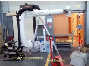
The developed technique was applied to the elastostatic calibration of robot Kuka KR-120. The parameters to be identified were the compliances k of the actuated joints and j the gravity compensator parameters s0,sV. To generate
de-flections in the actuated joints, the gravity forces 120 kg were applied to the robot end-effector (see Fig 3). The Carte-sian coordinates of three markers located on the tool (see Fig, 2) have been measured before and after the loading.
Gravity compensator
Tool
F
Test loading Force censor
Figure 3. Experimental setup for the identification of the elastostatic parameters.
To find optimal measurement configurations for calibra-tion, the design of experiments was used for six different an-gles q2 that are distributed between the joint limits. For each
2
q from three to seven optimal measurement configurations were found, which satisfy joint limits and physical con-straints related to the possibility carry out experiments. In to-tal 31 different measurement configurations and 186 meas-urements were considered for the identification, from which 7 physical parameters were obtained. The obtained experi-mental data have been processed using the identification al-gorithm presented in Section 3. Identified values for the ex-tended set of joint compliances (for 6 different angles q2) and
their confidence intervals are presented in Table 1. As fol-lows from this results, wrist compliances were identified with lower accuracy. The reason for it is smaller shoulder from the applied external forces comparing with manipulator joints. Relatedly small accuracy of first joint due to a smaller number of measurements in the experiments in which the de-flections were generated in the first joint. Further, obtained compliances k21… k26 were used to estimate pneumonic
compensator parameters by solving optimization problem (12). The identified joint compliances can be used to predict robot deformations under the external loading.
TABLE I. ELASTO-STATIC PARAMETERS OF ROBOT KUKA KR-120
Parameter value CI k1, [rad×μm/N] 1.13 ±0.15 (13.3%) k21, [rad×μm/N] 0.34 ±0.004 (1.1%) k22, [rad×μm/N] 0.36 ±0.005 (1.4%) k23, [rad×μm/N] 0.35 ±0.005 (1.4%) k24, [rad×μm/N] 0.28 ±0.007 (2.6%) k25, [rad×μm/N] 0.32 ±0.011 (3.6%) k26, [rad×μm/N] 0.26 ±0.007 (2.8%) k3, [rad×μm/N] 0.43 ±0.007 (1.8%) k4, [rad×μm/N] 0.95 ±0.31 (31.8%) k5, [rad×μm/N] 3.82 ±0.27 (7.0%) k6, [rad×μm/N] 4.01 ±0.35 (8.7%) V. CONCLUSIONS
The paper presents a new approach for the modelling and identification of the elastostatic parameters of heavy indus-trial robots with the pneumatic gravity compensator. It pro-poses a methodology and data processing algorithms for the identification of elastostatic parameters of gravity compensa-tor and manipulacompensa-tor. To increase the identification accuracy, the design of experiments has been used aimed at proper se-lection of the measurement configurations. In contrast to oth-er works, it is based on the industry oriented poth-erformance measure that is related to the robot accuracy under the load-ing. The advantages of the developed techniques are illus-trated by experimental study of the industrial robot Kuka KR-120, for which the joint compliances and parameters of the gravity compensator have been identified.
ACKNOWLEDGMENTS
The work presented in this paper was partially funded by Innopolis University and the project Partenariat Hubert Cu-rien SIAM 2016 France-Thailand.
REFERENCES
[1] W. Zhu, W. Qu, L. Cao, D. Yang, and Y. Ke, "An off-line programming system for robotic drilling in aerospace manufacturing,"
The International Journal of Advanced Manufacturing Technology,
vol. 68, pp. 2535-2545, 2013.
[2] M. Guillo and L. Dubourg, "Impact & improvement of tool deviation in friction stir welding: Weld quality & real-time compensation on an industrial robot," Robotics and Computer-Integrated Manufacturing, vol. 39, pp. 22-31, 6// 2016.
[3] B. Denkena and T. Lepper, "Enabling an Industrial Robot for Metal Cutting Operations," Procedia CIRP, vol. 35, pp. 79-84, // 2015. [4] C. Dumas, S. Caro, M. Cherif, S. Garnier, and B. Furet, "Joint
stiffness identification of industrial serial robots," Robotica, vol. 30, pp. 649-659, 2012.
[5] A. Nubiola and I. A. Bonev, "Absolute calibration of an ABB IRB 1600 robot using a laser tracker," Robotics and Computer-Integrated
Manufacturing, vol. 29, pp. 236-245, 2013.
[6] G. Alici and B. Shirinzadeh, "Enhanced stiffness modeling, identification and characterization for robot manipulators," Robotics,
IEEE Transactions on, vol. 21, pp. 554-564, 2005.
[7] A. Klimchik, D. Chablat, and A. Pashkevich, "Stiffness modeling for perfect and non-perfect parallel manipulators under internal and external loadings," Mechanism and Machine Theory, vol. 79, pp. 1-28, 9// 2014.
[8] U. Schneider, M. Momeni-K, M. Ansaloni, and A. Verl, "Stiffness modeling of industrial robots for deformation compensation in machining," in 2014 IEEE/RSJ International Conference on
Intelligent Robots and Systems, 2014, pp. 4464-4469.
[9] A. Klimchik, D. Bondarenko, A. Pashkevich, S. Briot, and B. Furet, "Compliance Error Compensation in Robotic-Based Milling," in
Informatics in Control, Automation and Robotics. vol. 283, J.-L.
Ferrier, A. Bernard, O. Gusikhin, and K. Madani, Eds., ed: Springer International Publishing, 2014, pp. 197-216.
[10] A. Klimchik, A. Pashkevich, D. Chablat, and G. Hovland, "Compliance error compensation technique for parallel robots composed of non-perfect serial chains," Robotics and
Computer-Integrated Manufacturing, vol. 29, pp. 385-393, 4// 2013.
[11] N. R. Slavkovic, D. S. Milutinovic, and M. M. Glavonjic, "A method for off-line compensation of cutting force-induced errors in robotic machining by tool path modification," The International Journal of
Advanced Manufacturing Technology, vol. 70, pp. 2083-2096, 2013.
[12] A. Klimchik, B. Furet, S. Caro, and A. Pashkevich, "Identification of the manipulator stiffness model parameters in industrial environment,"
[13] Y. Wu, A. Klimchik, S. Caro, B. Furet, and A. Pashkevich, "Geometric calibration of industrial robots using enhanced partial pose measurements and design of experiments," Robotics and
Computer-Integrated Manufacturing, vol. 35, pp. 151-168, 10// 2015.
[14] J. Hollerbach, W. Khalil, and M. Gautier, "Model Identification," in
Springer Handbook of Robotics, B. Siciliano and O. Khatib, Eds., ed:
Springer Berlin Heidelberg, 2008, pp. 321-344.
[15] A. Klimchik, Y. Wu, C. Dumas, S. Caro, B. Furet, and A. Pashkevich, "Identification of geometrical and elastostatic parameters of heavy industrial robots," in IEEE International Conference on Robotics and
Automation (ICRA) 2013, pp. 3707-3714.
[16] A. Klimchik, S. Caro, Y. Wu, D. Chablat, B. Furet, and A. Pashkevich, "Stiffness Modeling of Robotic Manipulator with Gravity Compensator," in Computational Kinematics. vol. 15, F. Thomas and A. Perez Gracia, Eds., ed: Springer Netherlands, 2014, pp. 185-192. [17] V. Arakelian, "Gravity compensation in robotics," Advanced Robotics,
vol. 30, pp. 79-96, 2016.
[18] C. Cho and S. Kang, "Design of a Static Balancing Mechanism for a Serial Manipulator With an Unconstrained Joint Space Using One-DOF Gravity Compensators," IEEE Transactions on Robotics, vol. 30, pp. 421-431, 2014.
[19] A. De Luca and F. Flacco, "A PD-type regulator with exact gravity cancellation for robots with flexible joints," in Robotics and
Automation (ICRA), 2011 IEEE International Conference on, 2011,
pp. 317-323.
[20] A. De Luca, B. Siciliano, and L. Zollo, "PD control with on-line gravity compensation for robots with elastic joints: Theory and experiments," Automatica, vol. 41, pp. 1809-1819, 10// 2005. [21] S.-F. Chen and I. Kao, "Conservative congruence transformation for
joint and Cartesian stiffness matrices of robotic hands and fingers,"
The International Journal of Robotics Research, vol. 19, pp. 835-847,
2000.
[22] J. K. Salisbury, "Active stiffness control of a manipulator in Cartesian coordinates," in Decision and Control including the Symposium on
Adaptive Processes, 1980 19th IEEE Conference on, 1980, pp.
95-100.
[23] S. J. Yan, S. K. Ong, and A. Y. C. Nee, "Stiffness analysis of parallelogram-type parallel manipulators using a strain energy method," Robotics and Computer-Integrated Manufacturing, vol. 37, pp. 13-22, 2// 2016.
[24] Y. Li and Q. Xu, "Stiffness analysis for a 3-PUU parallel kinematic machine," Mechanism and Machine Theory, vol. 43, pp. 186-200, 2008.
[25] D. Deblaise, X. Hernot, and P. Maurine, "A systematic analytical method for PKM stiffness matrix calculation," in Robotics and
Automation, 2006. ICRA 2006. Proceedings 2006 IEEE International Conference on, 2006, pp. 4213-4219.
[26] C. Gosselin and D. Zhang, "Stiffness analysis of parallel mechanisms using a lumped model," International Journal of Robotics and
Automation, vol. 17, pp. 17-27, 2002.
[27] J.-P. Merlet and C. Gosselin, "Parallel Mechanisms and Robots," in
Springer Handbook of Robotics, B. Siciliano and O. Khatib, Eds., ed:
Springer Berlin Heidelberg, 2008, pp. 269-285.
[28] A. Klimchik and A. Pashkevich, "Serial vs. quasi-serial manipulators: Comparison analysis of elasto-static behaviors," Mechanism and
Machine Theory, vol. 107, pp. 46-70, 1// 2017.
[29] K. Subrin, L. Sabourin, R. Cousturier, G. Gogu, and Y. Mezouar, "New Redundant Architectures in Machining: Serial and Parallel Robots," Procedia Engineering, vol. 63, pp. 158-166, // 2013. [30] Y. Guo, S. Yin, Y. Ren, J. Zhu, S. Yang, and S. Ye, "A multilevel
calibration technique for an industrial robot with parallelogram mechanism," Precision Engineering, vol. 40, pp. 261-272, 4// 2015. [31] B. Vemula, G. Spampinato, T. Brogardh, and X. Feng, "Stiffness
Based Global Indices for Structural Evaluation of Anthropomorphic Manipulators," in ISR/Robotik 2014; 41st International Symposium
on Robotics; Proceedings of, 2014, pp. 1-8.
[32] A. Pashkevich, A. Klimchik, and D. Chablat, "Enhanced stiffness modeling of manipulators with passive joints," Mechanism and
machine theory, vol. 46, pp. 662-679, 2011.
[33] A. Pashkevich, D. Chablat, and P. Wenger, "Stiffness analysis of overconstrained parallel manipulators," Mechanism and Machine
Theory, vol. 44, pp. 966-982, 2009.
[34] A. Klimchik, A. Pashkevich, S. Caro, and D. Chablat, "Stiffness matrix of manipulators with passive joints: computational aspects,"