is an open access repository that collects the work of Arts et Métiers Institute of Technology researchers and makes it freely available over the web where possible.
This is an author-deposited version published in: https://sam.ensam.eu Handle ID: .http://hdl.handle.net/10985/7467
To cite this version :
Guillaume FROMENTIN, Gérard POULACHON, Alphonse MOISAN - An Experimental and Analytical Method for Investigating Plastic Flow in Form Tapping - International Journal of Forming Processes - Vol. 9, n°4, p.1-16 - 2006
Any correspondence concerning this service should be sent to the repository Administrator : [email protected]
International Journal of Forming Processes. Volume 9 – n° 4/2006, pages 457 à 472
for Investigating Plastic Flow in Form
Tapping
Guillaume Fromentin — Gérard Poulachon — Alphonse
Moisan
LaBoMaP, ENSAM CER de CLUNY Rue Porte de Paris
71250 CLUNY
[email protected] [email protected]
RÉSUMÉ. Alors que les trous filetés sont réalisés par enlèvement de matière avec des tarauds coupants, dans le cas du taraudage par déformation, le taraud refoule la matière par écoulement plastique afin de former la section du filet. L’objet de ces investigations est d’étudier, expérimentalement et analytiquement, l’écoulement plastique tridimensionnel lors du taraudage par déformation d’un acier faiblement allié. Des expériences permettant la mesure du champ de déplacement sont proposées. Ces résultats expérimentaux sont ensuite utilisés pour faire des calculs analytiques. Le tenseur en grande déformation de Green Lagrange est déterminé à partir des déplacements. Le tenseur déviateur des contraintes est ensuite déterminé grâce à une loi de comportement du matériau taraudé. Enfin la condition d’équilibre permet de connaître le champ de contrainte résultant de procédé de taraudage par déformation. Le résultats obtenu est une quantification de l’écoulement plastique 3D, qui montre une couche limite très déformée à l’interface avec l’outil.
ABSTRACT. While threaded holes made by cutting taps result in material removal, in form tapping, the tap displaces the work material by plastic flow to form the thread section. The aim of the present work is to study, both experimentally and analytically, the 3D-plastic flow in form tapping of low-alloy steels. An experimental technique for producing and measuring the 3D displacement is proposed. Experimental results of displacements are used in the analytical analysis. The Green-Lagrange strain tensor is determined from the measurements obtained. The deviator stress tensor is calculated by using the constitutive law of the work material. The stress equilibrium allows the stress distribution resulting from the form tapping process. The results obtained show the quantification of the 3D-plastic flow, demonstrating that the external layer of the thread is strongly deformed.
KEYWORDS: form tapping, plastic flow, thread formation.
Nomenclature
p pitch (mm/rad)
r coordinates in radial direction
θ coordinates in tangential direction
z coordinates inaltitude direction
( , , )
e e e
r θ z cylindrical base vectoru
displacement vector of the work material (mm)( , , )
i∈ r z i i
u or U
θ displacement in direction I (mm)ε
strain tensor Dσ
deviator stress tensor (MPa)σ
stress tensor (MPa)eq
ε
equivalent Von Mises straineq
σ equivalent Von Mises stress (MPa)
P hydrostatic pressure (MPa)
1. Introduction
Form tapping is a different process from tapping by cutting for obtaining internal thread. In this second process, the thread results from chip removal, whereas in form tapping, the thread is formed solely by the displacements of the work material. Only a few studies have been carried out on form tapping, probably because the technical specifications for tapped holes are coming from cut tapping characteristics.
Recent interest in form tapping in manufacturing industries, in particular in the automotive industry, has been growing due to the inherent advantages of the process which include tool-life, better quality (Fromentin et al., 2005), better reliability, better cleanliness (no chips), and minimal quantity of lubricant application promoting environmentally conscious manufacturing. Therefore, in research on form taps, the process and the quality of the thread produced has picked up momentum.
Form taps are designed with lobes and taper, and their dimensions have to take into account the spring back of the deformed material (Zhitnitskii et al., 1965, Urlapov, 1969, Ivanov et al., 1996). The thread obtained is characterized by the occurrence of a split crest at the top of the thread, as shown in Figure 1. The thread percentage (the formation rate), and the necessary energy to form the thread depend
on the hole diameter before tapping (Agapiou, 1994). Experimental study also shows the influence of the design of the lobe both on torque and on the split crest formation (Warrington et al., 2005). The form tapping is available both with high ductile metals and alloys (Agapiou, 1994, Chowdhary et al., 2002) and hardened steels (Ivanov et al., 1996).
Figure 1. M12×1.5 formed thread on 42 CrMo 4 steel
Different analytical models of form tapping have been proposed. Henderer (Henderer et al., 1975) considers the form tapping operation as being one penetration of a single perfectly sharp leading wedge. Contrary of this, Chowdhary (Chowdhary et al., 2002, Chowdhary et al., 2003) defines more elaborate tools and takes into account all theirs teeth. In these two studies, the torque is modeled, and hypotheses are made concerning the geometry of the plastic flow. As a consequence, the 3D plastic flow leading to the displacement of the work material cannot be deduced from these models.
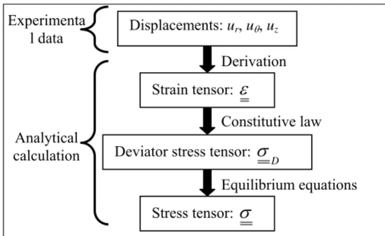
The present work is a contribution to the knowledge of the 3D material flow during form tapping. A method of investigating this flow is proposed. A mechanical approach based on the measurements of the displacement field and of its constitutive law is detailed in accordance with the diagram shown in Figure 2.
Figure 2. The proposed analytical method
The mechanical method proposed leads to an evaluation of the stresses useful for the thread strength, the stresses developed in the tool, and then for the optimization of thread forming conditions. Moreover, the experimental knowledge of the displacement can be used to confirm FEM simulations of form tapping.
The work material used for this study is a 42 CrMo 4 steel (AISI 4142) with a bainitic structure and 900 MPa ultimate tensile strength. Table 1 gives its chemical composition.
C Cr Mo Mn S P Si Ni Cu Al
0.411 1.072 0.168 0.028 0.021 0.014 0.169 0.128 0.195 0.011 Table 1. Chemical composition of 42 CrMo 4 steel (wt.%)
2. Displacement measurement 2.1. 3D plastic flow
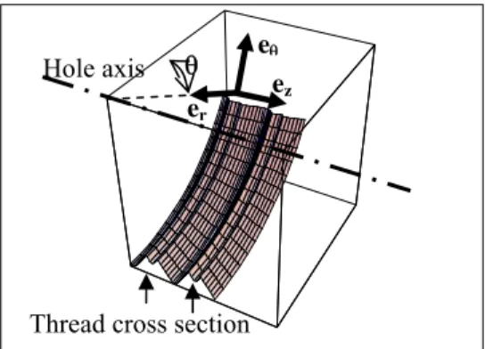
The thread formation resulting from the 3D plastic flow of the work material, as shown in Figure 3, can be broken down into three flow directions: axial, radial and tangential. The displacement field is expressed by equation [1] where cylindrical coordinates are used.
Displacements: ur, uθ, uz
Strain tensor:
ε
Deviator stress tensor: D
σ
Stress tensor:σ
Derivation Constitutive law Equilibrium equations Analytical calculation Experimenta l dataFigure 3. The 3D material plastic flow directions
( , , )r z
.
r ( , , )r z.
( , , )r z.
zr z
u
=
u
θe
+
u
θ θe
θ+
u
θe
[1]In fact, because the final geometry of the thread is a helix, each component of this field vector is a function of only 2 parameters as shown in equation [2]. “p” is the pitch per radian and is equal to the pitch divided by 2π in mm.rad-1.
( , , )r z ( ,r z p. ) , i ( , , )r z
i i
u
θ=
U
+ θ ∈ θ [2]The tool used is a M12×1.5 6HX form tap. It is designed with five lobes and a short entry taper with three pitches. The hole diameter is equal to 11.36 mm, so the thread percentage is 85%. Blind holes are tapped by using a floating holder and an extreme pressure oil containing sulfonate additives. The spindle speed is fixed at 370 rpm, which corresponds to 14 m.min-1 tangential speed on the nominal diameter
of the tool.
Three different workpieces, shown in Figure 4, are needed to measure the displacement field in the three directions. The principle is to tap a workpiece composed of two parts assembled with screws (not visible on Figure 4). The two assembly surfaces in contact are flat and ground before assembly. The mean pressure at the assembly surface caused by the screws is lower than 10 MPa, i.e., this stress is negligible compared to the yield stress of the work material. After assembly and before tapping, drilling and boring operations are performed in order to obtain a hole having a good accuracy and straightness. After form tapping, due to the plastic flow resulting from this operation, the inner surfaces are deformed, and thus, are locally not planar. The difference between these two states is equal to the component of the displacement in the normal direction of the initial surface, i.e., flat assembly surface. The workpiece is composed of two parts; consequently it limits the tangential stress in the assembled surfaces which can be transmitted during flowing. Nevertheless, the displacement is measured perpendicularly to the plane, thus it is assumed that there is little influence on the flow of the work material.
Thread cross section Hole axis
ez er
eθ
Figure 4. The experimental principle for displacement measurements
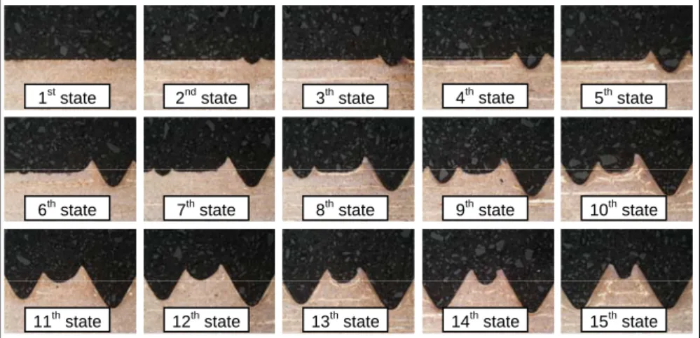
Figure 5 shows the different formation states of the thread along the tapping operation. The experimental method leads to the measurement of the displacement between the initial state, i.e., the hole surface (1st state), and the final state, i.e., the
threaded hole (15th state). This transformation results from the action of ten lobes of
the tap on both sides on the thread section. The displacement caused by each lobe of the tap is not measured. The 6th state shows the thread formed after only one lobe
having worked on the left side of the thread and six lobes on the other.
Figure 5. Different stages of the thread formation (Fromentin et al., 2002)
2.1. Measurement of the tangential displacement Uθ
In order to measure the tangential displacements, the assembled surfaces contain the axis of the hole, as shown in Figure 4(a). Consequently, in this configuration the normal direction of the surfaces is the tangential direction of flow eθ. Practically, the
er
ez
1st state 2nd state
3thstate 4thstate
6th state 7th state 8thstate 9thstate
11th state 12th state 13thstate 14thstate
5th state
10th state
15th state
(a) tangential (b) radial (c) axial Part 1a
Part 2a Part 2b Part 2c
Part 1b Part 1c ez eθ ez ez er eθ Δ
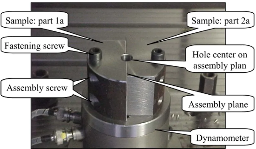
experiment is shown Figure 6. The two parts of the sample are assembled and fastened on a Kistler 9273 dynamometer with M8 screws.
Figure 6. Experiment for measuring the tangential displacement
Figure 7 shows the surface deformed in the tangential direction eθ due to the
work material flow. The tangential displacement, Uθ, is equal to the altitude
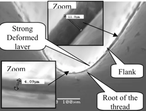
variation relative to the initial flat surface. It shows that the tangential displacement becomes ever higher when the point under consideration is closer to the flank and the top of the thread. In Figure 8, a discontinuity is visible on the deformed surface. A 4-11 μm thin deformed layer along the flank and the root of the thread appears. This may be explained by a large shearing stress linked to the friction with the tool. The inside of the thread - zone far from the tool - undergoes no tangential displacement.
Figure 7. SEM picture of the tangential displacement
Dynamometer Sample: part 1a Assembly screw Assembly plane Hole center on assembly plan Fastening screw Assembly screw Sample: part 2a
U
θ max Split crest Root Flank Initial assembly surfaceDeformed surface
Figure 8. SEM picture of the strong deformed layer
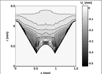
The deformed surface is measured on a 10 μm square grid with a 3D scanning device using a stylus having a 30° angle and a 25 μm radius. Figure 9 shows the cartography of the tangential displacement in the cross section of the thread. The maximum displacement, Uθ max, reaches the value of 0.6 mm. The tangential
displacement is very important. It is responsible for the torque during tapping, and it is not necessary to form the cross section of the thread. Only the radial and axial displacements are the flows which contributed to form the thread section. An optimization of this process would have the goal of reducing the tangential flow by changing the fluid or the tool geometry for example.
Figure 9. Tangential displacement Uθ(r,z)
2.2. Measurement of the radial displacement Ur
The experiment was carried out on the sample presented in Figure 4(b). In this case, as shown in Figure 10, the assembly surfaces are shifted Δ mm from the axis
Zoom Zoom Root of the thread Flank Strong Deformed layer -0.6 -0.5 -0.4 -0.3 -0.2 -0.1 0 0.5 1 1.5 5 5.5 6 6.5 z (mm) r ( mm) Uθ (mm)
of the hole. Except for this point, the experiment is the same as the previous one for measuring the tangential displacement. Because the assembly surfaces do not contain the hole axis, the component of the measured displacement vector, named urθ, is both linked to the tangential displacement, uθ, which is now known, and to the
radial displacement ur. Figure 10 shows how it is possible from this setup to
calculate the radial displacement ur at M(r, θ) point. Its expression is given by
equations [3] and [4].
Figure 10. Top view of the radial displacement
-arcsin(
r
)
θ
=
Δ
[3](
-
cos ) sin
r ru
u
u
θ θθ
θ
=
[4]The deformed surface giving the displacement urθ is measured with the same
method as the tangential displacement uθ. From this data the radial displacement is
computed by using equation [3] and [4]. Figure 11 shows the radial displacement. It is the largest on the top of the thread flanks. The work material is moved towards the hole axis direction to form the thread, but the inside of the thread is very little displaced. This explains the occurrence of a split crest at the top of the thread.
Part 1b Part 2b uθ U ur urθ Δ r θ Assembly surfaces M(r,θ) ez
Figure 11. Radial displacement Ur(r,z)
3.2. Measurement of the axial displacement Uz
In this experiment, the assembly surfaces are orthogonal to the hole axis as shown in Figure 4(c). Thus, the measured component of the displacement is directly the axial displacement. Practically, the experiment is shown in Figure 12. The two parts of the sample are assembled and fastened on the dynamometer with M8 screws.
Figure 12. Experiment for measuring the axial displacement
The deformed surface is measured as were the previous ones, and shown in Figure 13. This surface enables us to know the axial displacement along a
-0.5 -0.4 -0.3 -0.2 -0.1 0 0 0.5 1 1.5 5 5.5 6 6.5 z (mm) r ( mm) Ur (mm) Dynamometer Sample: part 2c Sample: part 1c Fastening screws Assembly plane Hole Form tap
revolution that corresponds from the axial position z = 0 to the axial position z = pitch. The change of Cartesian coordinates to cylindrical coordinates enables the drawing of the displacement Uz(r,z) as shown in Figure 14. The zones of the work
material which submit the maximum axial displacement are still on the top of the thread flanks. This maximum value, Uz max, is about 0.6 mm. In fact, the surface of
the split crest was initially the surface of the hole before tapping, as shown in the 1st
state to the 15th state on Figure 5. Therefore, it is obvious that the area at the top of
the split crest moved from a position z = 0 to a position z = Uz max.
Figure 13. Axial displacement surface (mm)
Figure 14. Axial displacement Uz(r,z)
-0.6 -0.4 -0.2 0 0.2 0.4 0.6 0 0.5 1 1.5 5 5.5 6 6.5 z (mm) r ( mm) Uz (mm)
3. Analytical calculation
The global displacement field is now known. It allows the calculation of the strains and stresses resulting from the plastic flow. Figure 2 shows the approach used to achieve the stress values. This takes into account only the strain hardening and not the strain-rate and the thermal softening. These last two are unknown and assumed to have a secondary importance compared to the strain hardening in this process. The form tapping is quite a low speed process, and no speed effect has been observed during tests, as the prevalent strain rates are low. Moreover, it is considered that the heat generated inside the work material by the plastic deformation is quite rapidly conducted into the work material and the temperature does not exceed 400-450 °C because no metallurgical transformation of the bainite to a ferrito-pearlitic one is observed.
3.1. Strain tensor calculation
The displacements from the initial undeformed state, to the final state which is the formed thread, are known. This process induces high strain, thus, the calculated strain tensor is the Green-Lagrange tensor, as expressed in equation [5].
[ ]
[ ]
[ ]
[ ]
(
)
1
2 .
T T
grad u grad u grad u grad u
ε
= + + [5]To examine only one computed value, the equivalent Von Mises strain is calculated with equation [6]. Figure 15 shows the results. The strain is most important along the root, the flank and the split crest. It reaches 300%, which is a realistic value and shows the significance of strain resulting from the form tapping.
( )
2 3
eq Tr ε ε
Figure 15. Equivalent Von Mises strain
3.2. Deviator stress tensor calculation
The deviator stress tensor is obtained from the strain tensor by using a Norton Hoff constitutive law which takes into account only the strain hardening as shown in equation [7]. The values of (A,B,n) constants used (cf. Table 2) are coming from a study made by Grolleau on the same work material (Grolleau, 1996) and were identified through Hopkinson bar tests in a limited range of strain.
(
)
2 , ( , ) ( , , ) ,.
, n i j r z D i jA
B
i j θσ
=
+
ε
∈ [7] A (MPa) B (MPa) n 598 768 0.210Table 2. Coefficient of the Norton Hoff constitutive law of 42 CrMo 4 steel
3.3. Stress tensor calculation
The relation between the stress tensor and the deviator stress tensor is given by equation [8], P being the hydrostatic pressure, i.e., it is the trace of the stress tensor. By neglecting the gravity and the acceleration effects, the stress equilibrium equation is written as equation [9]. From equations [8] and [9], the three partial differential equations are deduced (cf. equation [10]). It allows the computation of the hydrostatic pressure, thus, the calculation of the stress tensor.
1 3
. .
DP I
σ σ
=
+
[8]div
⎡ ⎤
⎣ ⎦
σ
=
O
[9].
3.
Ddiv P I
⎡
⎣
⎤
⎦
=
div
⎡
⎣
σ
⎤
⎦
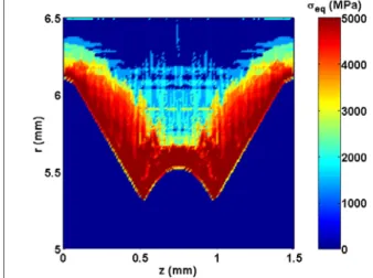
[10]From equation [11], the equivalent Von Mises stress is computed and Figure 16 shows the results. The equivalent stress reaches 5,000 MPa, and σij does not exceed
3,800 MPa. The stress values seem to be important but can be explained in different ways. The constitutive law maximizes the stresses because it is used in a too high strain range. The stresses are also overestimated by the fact that the approach does not take into account the thermal softening which would reduce these values. Moreover, the mechanical laws are not valid in the zones strongly deformed such as the tool-thread interfaces where the stresses are the largest. The microhardness measured directly on the flank is 770 ± 30 HV, the initial state being 290 HV. Consequently, stress values around 3,000 MPa would be more realistic.
(
)
3 2
eq Tr D D
Figure 16. Equivalent Von Mises stress (MPa)
4. Discussion
The proposed method is based on experimental data and provides new knowledge of the strain field involving 3D plastic flow in form tapping. A previous study (Chandra, 1975) introduces the idea of using a grid method to investigate form tapping. One drawback of applying this method to the investigation of form tapping, which leads to a 3D plastic flow, is that it remains limited to the measurement of the radial and axial displacement. Nevertheless, the grid method has been applied in our tapping test and the results concerning the radial and axial displacement are consistent and correlate well with the findings of our new method, allowing the measurement of the three displacements in three steps.
Several applications of this new method of analysis are possible. Among them, there is the study of parameter effects on the process and on the mechanical state of the thread. The hole-diameter before tapping is one of parameters having the most significant effect in thread formation (Fromentin et al., 2002), because it changes the volume of the work material displaced. The fluid use has also to be considered carefully. The use of an emulsion or an oil containing extreme pressure additives leads to different torques (Ivanov et al., 1996, Fromentin et al., 2006). The fluid influences the friction between the tap and the work material; as a consequence, it modifies the strain and the stress field.
5. Conclusion
It has been shown that the form tapping process involves 3D plastic flow of the work material. The present study makes a contribution to the characterization of the 3D plastic flow resulting from this process. A new experimental method is proposed to determine the displacement field. Moreover, this study reveals the importance of the tangential flow. It is synonymous with high strains, and a highly deformed layer has been observed. An analytical approach is also proposed to calculate the strain and the stress distributions by taking into account the strain hardening effect.
The numerical simulation of form tapping is difficult to realize due to the fact that it involves a 3D plastic flow with a multi-edge tool, and leads to long calculation time; simplified approaches are also needed. In the future, the experimental data of the present study will be useful to compare the findings from methods such as FEM.
6. References
Agapiou J.S., Evaluation of the effect of high speed machining on tapping, Journal of
Manufacturing Science & Engineering ASME 116, 1994, p. 457-462.
Chandra R., Das S.C., Forming taps and their influence on production, Journal of India
Engineering, vol. 55, 1975, p. 244-249.
Chowdhary S., Burak Ozdoganlar O., Kapoor S.G., DeVor R.E., Modeling and analysis of internal thread rolling, Transactions of the NAMRI of SME, 2002, p. 329-336.
Chowdhary S., Kapoor S.G., DeVor R.E., Modeling forces including elastic recovery for internal thread forming, Journal of Manufacturing Science & Engineering ASME, vol. 125, 2003, p. 681-688.
Fromentin G., Poulachon G., Moisan A., An experimental study on the effects of lubrication in form tapping, Tribology International, 2006, to be published.
Fromentin G., Poulachon G., Moisan A., Precision and surface integrity of internal threads obtained by form tapping, Manufacturing Technology, CIRP Annals, STC S, Vol. 54/1, 2005, p. 519-522.
Fromentin G., Poulachon G., Moisan A., Metallurgical aspects in cold forming tapping, Proceedings of the 18th International Conference on Manufacturing Research, 10-12 September 2002, p. 373-377.
Fromentin G., Poulachon G., Moisan A., Thread forming tapping of alloyed steel, Proceedings of the 3rd CIRP International Seminar on Intelligent Computation in
Manufacturing Engineering, 3-5 July 2002, p. 115-118.
Grolleau V., Approche de la validation expérimentale des simulations numériques de la coupe avec prise en compte des phénomènes locaux à l’arête de l’outil, PhD Thesis, 1996, Nantes University, France, FD-82-216.
Henderer W.E., Von Turkovich B.F., Theory of the cold forming tap, Annals of the CIRP, vol. 23, 1974, p. 51-52.
Ivanov V., Kirov V., Rolling of internal threads: Part 1, Journal of Materials Processing
Technology, vol. 72, 1996, p. 214-220.
Urlapov G.P., Fluteless taps, Machine & Tooling, vol. 15, n°10, 1969, p. 46-48.
Warrington C., Kapoor S. G., De Vor R. E., Experimental Investigation of Thread Formation in Form Tapping, Journal of Manufacturing Science & Engineering ASME, vol. 127, 2005, p. 829-836.
Zhitnitskii S.I., Andreichikov O.S, Rolling tool for rolling internal thread, Machine &

![Figure 10. Top view of the radial displacement -arcsin( r )θ=Δ [3] ( - cos ) sin r ruu uθ θ θ θ= [4]](https://thumb-eu.123doks.com/thumbv2/123doknet/7276507.206955/10.892.311.581.363.562/figure-view-radial-displacement-arcsin-δ-cos-sin.webp)