Current-driven dynamics of chiral ferromagnetic domain walls
The MIT Faculty has made this article openly available. Please sharehow this access benefits you. Your story matters.
Citation Emori, Satoru, Uwe Bauer, Sung-Min Ahn, Eduardo Martinez, and Geoffrey S. D. Beach. “Current-Driven Dynamics of Chiral Ferromagnetic Domain Walls.” Nature Materials 12, no. 7 (June 16, 2013): 611–616.
As Published http://dx.doi.org/10.1038/nmat3675
Publisher Nature Publishing Group
Version Author's final manuscript
Citable link http://hdl.handle.net/1721.1/91618
Terms of Use Article is made available in accordance with the publisher's policy and may be subject to US copyright law. Please refer to the publisher's site for terms of use.
1
Current-driven dynamics of chiral ferromagnetic domain walls
Satoru Emori1, Uwe Bauer1, Sung-Min Ahn1, Eduardo Martinez2, and Geoffrey S. D. Beach1*
1
Department of Materials Science and Engineering, Massachusetts Institute of Technology, Cambridge, Massachusetts 02139, USA
2
Dpto. Física Aplicada. Universidad de Salamanca,
Plaza de los Caidos s/n E-38008, Salamanca, Spain
In most ferromagnets the magnetization rotates from one domain to the next with no preferred handedness. However, broken inversion symmetry can lift the chiral degeneracy, leading to topologically-rich spin textures such as spin-spirals1,2 and skyrmions3–5 via the Dzyaloshinskii-Moriya interaction (DMI)6. Here we show that in ultrathin metallic ferromagnets sandwiched between a heavy metal and an oxide, the DMI stabilizes chiral domain walls (DWs)2,7 whose spin texture enables extremely efficient current-driven motion8–11. We show that spin torque from the spin Hall effect12–15 drives DWs in opposite directions in Pt/CoFe/MgO and Ta/CoFe/MgO, which can be explained only if the DWs assume a Néel configuration7,16 with left-handed chirality. We directly confirm the DW chirality and rigidity by examining current-driven DW dynamics with magnetic fields applied perpendicular and parallel to the spin spiral. This work resolves the origin of controversial experimental results10,17,18 and highlights a new path towards interfacial design of spintronic devices.
2
Current-controlled DW displacement underpins the operation of an emerging class of spintronic memory19 and logic20,21 devices. In out-of-plane magnetized ferromagnets sandwiched between an oxide and a heavy metal, current-induced DW motion is anomalously efficient.8–11 This observation has been widely attributed to a Rashba effective field17,22,23 that stabilizes Bloch DWs against deformation, permitting high-speed motion10 via conventional spin-transfer torque (STT)24. However, current-induced DW motion is absent in symmetric Pt/Co/Pt8,9,11,25 stacks, and semiclassical transport calculations25 suggest the spin-polarized current in the ultrathin (< 1 nm) Co is vanishingly small. Moreover, DWs in Pt/Co/oxide move against electron flow8,10,11, contrary to the action of STT24. Together, these results suggest that conventional STT contributes negligibly to DW dynamics in these ultrathin structures and that interfacial phenomena26,27 are instead responsible.
The Rashba field lacks the correct symmetry to drive DWs directly16,26,27, and the spin Hall effect (SHE) in the adjacent heavy metal has emerged as a possible alternative mechanism12–16,27. SHE-driven spin accumulation at the heavy-metal/ferromagnet interface generates a Slonczeswki-like torque16,26,27 strong enough to switch uniformly-magnetized films12–15,18. However, the Bloch DWs expected in typical nanowire geometries8–11,28 have their plane oriented perpendicular to the nanowire axis, in which case the Slonczewski-like torque vanishes16. This behavior was recently confirmed in asymmetric Pt/Co/Pt stacks in which the SHE-induced torques from the Pt layers did not cancel completely15. In that case, current-assisted DW depinning was observed when an applied field rotated the DW plane towards the current axis, but up-down and down-up DWs were driven in opposite directions and the current had no effect in the absence of the bias field. The SHE alone is therefore incapable of uniformly
3
driving trains of DWs in devices, and is insufficient to explain the high spin-torque efficiencies and DW velocities observed in Pt/Co/oxide8–11 without applied fields.
Here we characterize current-induced torques and DW dynamics in out-of-plane magnetized Pt/CoFe/MgO and Ta/CoFe/MgO stacks that are nominally identical except for the heavy-metal underlayers, whose spin Hall angles are large and of opposite sign12–14. By considering the symmetry of the measured current-induced torque along with the DW dynamics driven by this torque, we uniquely identify the DW configuration as Néel with a fixed chirality. Magnetostatics alone makes this configuration unstable and does not favor one chirality over the other, but the DMI has been theoretically shown to promote chiral Néel DWs2,7. By applying in-plane magnetic fields, we verify that the DW magnetization aligns rigidly along the nanowire axis, and that the DW spin spiral exhibits a global chirality common to both Pt/CoFe/MgO and Ta/CoFe/MgO. Current-driven DW motion in heavy-metal/ferromagnet/oxide structures is naturally explained by the combination of the SHE, which produces the sole current-induced torque, and the DMI, which stabilizes chiral DWs whose symmetry permits uniform motion with very high efficiency.
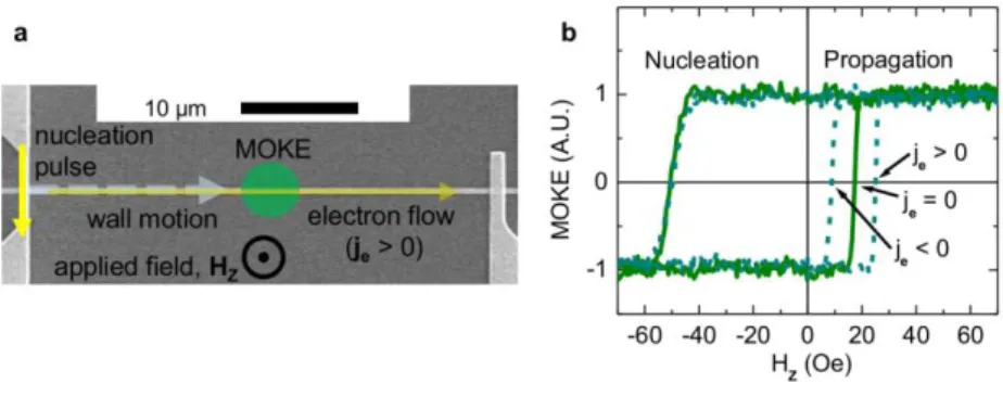
DW motion was characterized in 500-nm wide, 40-μm long nanowires overlaid with an orthogonal DW nucleation line and lateral contacts for current injection (Fig. 1a). We first examine the effect of current on the threshold field Hprop for DW propagation through the defect landscape. Measurements were performed as in Ref. 11, by first nucleating a reversed domain with the Oersted field from a current pulse through the nucleation line and then sweeping an out-of-plane field Hz to drive the DW along the nanowire. DW motion was detected via the polar magneto-optical Kerr effect, with a ~3 m laser spot positioned at the midpoint of the nanowire. Comparing Figs. 1d,e, Hprop varies linearly with electron current density je, but DW propagation
4
is hindered in the electron flow direction in Pt/CoFe/MgO and assisted along electron flow in Ta/CoFe/MgO. This remarkable difference, produced simply by changing the nonmagnetic metal in contact with the ferromagnet, was independent of the sense of magnetization (up-down or down-up) across the DW. The magnitude of the spin-torque efficiency, taken as the slope of Hprop versus je, was 120 Oe/1011 A m-2 for Pt/CoFe/MgO and 170 Oe/1011 A m-2 for Ta/CoFe/MgO. These large efficiencies are comparable to those reported for Pt/Co/AlOx9,10 and Pt/Co/GdOx11, suggesting that a universal mechanism governs current-driven DW motion in heavy-metal/ferromagnet/oxide.
In Figs. 1f,g, we directly compare field-driven and current-driven DW velocities, measured using a time-of-flight technique11. Again, DWs moved against electron flow in Pt/CoFe/MgO (Fig. 1f) and along electron flow in Ta/CoFe/MgO (Fig. 1g). The maximum field was limited by random domain nucleation, and the exponential dependence of velocity on Hz and je indicates thermally activated motion11,29. The field-driven and current-driven velocities exhibit the same dynamical scaling across three decades in velocity when je is scaled by a constant (110 Oe/1011 A m-2 for Pt/CoFe/MgO and 160 Oe/1011 A m-2 for Ta/CoFe/MgO). These field-to-current ratios closely match those extracted from Figs. 1d,e. We therefore conclude that the effect of current on DW motion is phenomenologically equivalent to an out-of-plane field9,11, which reveals the symmetry of the current-induced torque as discussed later in this Letter.
In addition to robust DW motion, current enables switching between uniformly magnetized “up” and “down” states with the assistance of a constant in-plane magnetic field12,15,18. This switching phenomenon was demonstrated in 1200-nm wide Hall crosses (Fig. 2a). A sequence of 250-ms long current pulses with increasing (or decreasing) amplitude was injected along the x-axis, and in between each pulse the out-of-plane magnetization component
5
Mz was measured from the anomalous Hall voltage using a low-amplitude (~109 A m-2) AC sense current and a lock-in amplifier. Figs. 2d,e plot Mz versus je, under a constant applied longitudinal field HL. This field tilted the magnetization away from the z-axis by ≈ 5o in Pt/CoFe/MgO at 500 Oe and ≈ 3o in Ta/CoFe/MgO at 100 Oe, but did not bias Mz up or down, as evidenced by the nearly symmetric switching profile (Figs. 2d,e). With sufficiently large HL and je in the +x direction, the up magnetized state was favored in Pt/CoFe/MgO (Fig. 2d, solid line), whereas the down state was favored in Ta/CoFe/MgO (Fig. 2e, solid line). When the direction of HL or je was reversed, the preferred magnetization direction was also reversed (Figs. 2d, e, dotted lines).
This switching behavior implies that je generates an effective field HSL
associated with a
Slonczewski-like torque12,13,15,18, given byHSL HSL0
mˆ
zˆ ˆje
16. Here mˆ , zˆ, and jˆe are unit vectors along the magnetization, z-axis, and electron flow, respectively, and 0SL
H parameterizes the torque. The SHE in the heavy metal directly generates a Slonczewski-like torque, but the Rashba effect can also yield a torque of this form due to spin-relaxation18,26,27. Assuming the SHE is the dominant source, justified experimentally below, 0
SL
H is related to the spin Hall angle
SH
in the heavy metal viaHSL0 SH je | (2eMStF) 16
, with M the saturation magnetization S and t the ferromagnet thickness. From the sign of F 0
SL
H extracted from current-induced switching (Figs. 2b,c), SH is positive in Pt and negative in Ta, consistent with Refs. 12 and 13.
We quantified the Slonczewski-like torque by detecting current-induced magnetization tilting using the technique in Ref. 30. AC current exerts a periodic torque on the uniformly magnetized state, causing Mz to vary at the drive frequency, . This leads to first and second harmonics in the anomalous Hall voltage, V and V2, from which the magnetization tilting can
6
be determined22,30. We measured V and V2 while quasistatically sweeping a longitudinal field
L
H , and extracted HSL via HSL 2
dV2 /dHL
d2V /dHL2
(Ref. 30, Supplementary Information). Measurements were performed at several AC amplitudes to extract the scaling ofSL
H with current. When the magnetization was up and je was in the +x direction, H pointed SL
along -x in Pt/CoFe/MgO (Figs. 3a,e) and +x in Ta/CoFe/MgO (Figs. 3b,f), in agreement with our analysis of magnetization switching (Figs. 2b, c). The direction of H reversed when the SL magnetization was oriented down. The linear fit in Fig. 3a reveals a large 0
SL
H in Pt/CoFe/MgO of magnitude 50 Oe per 1011 A m-2, implying SH= +0.06 in Pt, which agrees well with Ref. 12. The magnitude of 0
SL
H in Ta/CoFe/MgO is ≈ 200 Oe per 1011 A m-2, implying SH = -0.25 in Ta, twice as large as in Ref. 13 and closer to the value reported for W14.
The current-induced effective transverse field HFL, often associated with a “field-like” torque from the Rashba effect16,17,22,23,26,27, was quantified similarly by sweeping an applied transverse field H : T HFL 2
dV2 /dHT
d2V /dHT2
. UnlikeHSL, the direction of HFLwas independent of the magnetization orientation (Figs. 3 c,d). The magnitude of HFL in Pt/CoFe/MgO (Fig. 3c) was ≈ 20 Oe/1011 A m-2, two orders of magnitude lower than reported in Refs. 17 and 22, although its directionality was the same as in Pt/Co/AlOx17,22. Since current-induced DW motion had a very high efficiency and occurred against the electron flow direction in Pt/CoFe/MgO, the fact that HFL was negligible indicates that the Rashba effect cannot be the source of these features8–11,26,27. Furthermore, since any contribution to the Slonczewski-like torque by the Rashba effect18 enters as a correction proportional to the nonadiabicity parameter
7 << 126,27
, the fact that HSL is here much larger than HFL implies that the Rashba effect contributes negligibly to the Slonczewski-like torque.
In Ta/CoFe/MgO (Fig. 3d), HFL was by contrast quite large, ≈ 400 Oe/1011 A m-2, and its direction was the same as in Ta/CoFeB/MgO23 and opposite to Pt/CoFe/MgO and Pt/Co/AlOx17,22, suggesting a strong Rashba field17,22,23 in this sample. However, as noted in Ref. 12, macrospin modeling shows that a large Slonczewski-like torque can pull the magnetization out of the x-z plane, which in the measurements here and elsewhere17,22,23,30 would have a similar effect as a field-like torque. Considering the weaker perpendicular magnetic anisotropy (see Methods) and the much larger 0
SL
H in Ta/CoFe/MgO compared to Pt/CoFe/MgO, the Slonczewski-like torque could contribute to the apparently large HFL.
As summarized in Figs. 3e,f, the current-induced torques are opposite in Pt/CoFe/MgO and Ta/CoFe/MgO, as are the direction of current-driven DW motion and the sign of the spin Hall angles in Pt and Ta. Here we consider in detail the case of Pt/CoFe/MgO, in which the field-like torque is unambiguously small. One-dimensional (1D) model calculations29 in Fig.4b (see Methods and Supplementary Information) show that Bloch DWs cannot be driven by the SHE alone, in agreement with prior reports16,27 and with the symmetry of the Slonczewski-like torque. In the 1D model with SH > 0 and with no transverse Rashba field, the addition of conventional STT enables sustained DW motion, but its direction is along electron flow (Fig. 4b). No combination of the SHE and STT reproduces the experimentally-observed DW motion against electron flow (Supplementary Information), and moreover conventional STT is likely absent as argued above. Thus, an alternate mechanism is required whereby the SHE alone can drive DW motion.
8
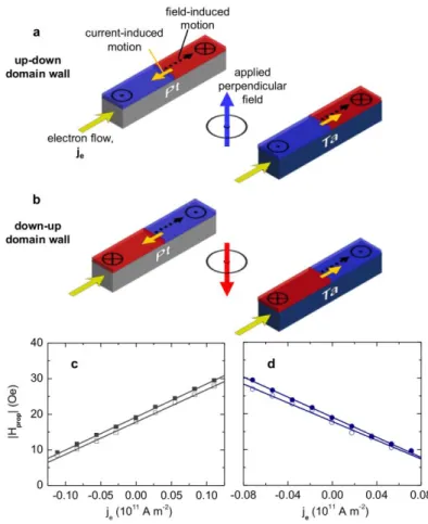
Néel DWs have an internal magnetization that would align with the nanowire axis, such that the Slonczewski-like torque would manifest as a z-axis field16 as experimentally observed (Fig. 1). However, the direction of HSL depends of the sense of the DW magnetization, and the direction of DW motion varies accordingly (Supplementary Information). Fig. 4a illustrates Néel DWs with oppositely-directed internal magnetization for up-down and down-up transitions, exhibiting a left-handed chiral texture2. Based on the sign of the measured Slonczewski-like torque (Figs. 2 and 3), these chiral DWs move against electron flow in Pt/CoFe/MgO and along electron flow in Ta/CoFe/MgO. Although Bloch DWs are magnetostatically preferred28, adding the DMI to the 1D model stabilizes such chiral Néel DWs7 (Methods, Supplementary Information), leading to qualitative behavior in agreement with experiment (Fig. 4b).
Finally, we assess the rigidity and chirality of the Néel DWs in Pt/CoFe/MgO using applied in-plane fields. In Figs. 4c,d we show that the spin-torque efficiency, extracted similarly to Fig. 1d, is insensitive to HL up to at least 600 Oe, but declines significantly with increasing |HT|. This behavior is opposite to that reported for Bloch DWs in Ref. 15, but is precisely what is expected for DMI-stabilized Néel DWs: HL is collinear with the DW magnetization and exerts no torque, whereas HT exerts a torque that cants the DW magnetization away from the x-axis and reduces the z-axis-oriented HSL. That the sense of internal DW magnetization could not be reversed at the experimentally-available maximum HL of 600 Oe attests to the strength of the DMI in this system.
We also measured the effects of HL and HT on the velocity of fast current-driven DWs (Figs. 4e,f), which was reproduced qualitatively by the 1D model with the SHE and DMI (Figs. 4 g,h). HL modified the velocities of up-down and down-up DWs with opposite slopes (Figs. 4e,g), whereas HT modified both velocities identically (Figs. 4f,h). The 1D model predicts DW motion
9
reversal under very large HL coinciding with reversal of the DW sense, and impeded motion for large HT due to rotation towards a Bloch configuration (see Supplementary Information). Interestingly, the velocity increased with HT in the direction of the previously reported Rashba field in Pt/Co/AlOx10,17,22, although here HFL in Pt/CoFe/MgO was vanishingly small. Our experimental and computational results indicate that, even without the Rashba effect, HT can modify the dynamics of Néel DWs driven by the SHE-induced Slonczewski-like torque.
In summary, we show that current alone drives DWs with high efficiency but in opposite directions in Pt/CoFe/MgO and Ta/CoFe/MgO through the Slonczewski-like torque due to the SHE12–15. However, the SHE-induced torque alone cannot directly drive the magnetostatically-preferred Bloch DWs28 in these materials. We show experimentally and computationally that the DMI1–7 provides the missing ingredient to explain current-induced DW motion in heavy-metal/ferromagnet/oxide systems8–11 by stabilizing Néel DWs with a built-in chirality, such that the SHE alone drives them uniformly and with high efficiency. Engineering both the DW spin structure and the current-induced torque simply by selecting the materials adjacent to the ferromagnet presents unprecedented opportunities for designing current-controlled spintronic devices.
Methods
Sample fabrication. The stack structure of Pt/CoFe/MgO was Ta(3 nm)/Pt(3 nm)/Co80Fe20(0.6 nm)/MgO(1.8 nm)/Ta(2 nm), and that of Ta/CoFe/MgO was Ta(5 nm)/Co80Fe20(0.6 nm)/MgO(1.8 nm)/Ta(2 nm). Both were deposited on Si/SiO2(50 µm) substrates. The metal layers were deposited by DC magnetron sputtering at 2 mTorr Ar (for Pt, 3 mTorr Ar), and MgO was RF sputtered at 3 mTorr Ar. The deposition rates were < 0.1 nm s
-10 1
,calibrated with X-ray reflectivity. Co80Fe20 was chosen, instead of pure Co, to attain sufficient perpendicular magnetic anisotropy on both Ta and Pt underlayers. The bottom Ta(3 nm) layer in Pt/CoFe/MgO served as a seed layer to enhance perpendicular magnetic anisotropy and adhesion between Pt and the substrate. The Ta(2 nm) capping layer protected the MgO layer in each structure. Vibrating sample magnetometry on continuous films revealed full out-of-plane remanent magnetization and in-plane (hard-axis) saturation fields of ≈ 5 kOe for Pt/CoFe/MgO and ≈ 3 kOe for Ta/CoFe/MgO. The saturation magnetization was ≈700 emu/cm3
, approximately half of the bulk value, suggesting a magnetic dead layer due to roughness or oxidation. Both films exhibited weak DW pinning, with DW propagation at fields < 20 Oe.
The nanowires and Hall crosses were fabricated using electron beam lithography, magnetron sputtering, and liftoff. Electrical contacts consisting of Ta(2 nm)/Cu(100 nm) were placed with a second layer of electron beam lithography. To estimate the current density through these devices, current was assumed to flow only through the ultrathin CoFe layer and the adjacent heavy metal layer, so that the effective conductive thickness was 3.6 nm for Pt/CoFe/MgO and 5.6 nm for Ta/CoFe/MgO. We neglected current shunting in the bottom Ta seed layer in the Pt/CoFe/MgO, as sputtered Ta (beta phase) typically has a much higher resistivity than Pt. The resistance of the Ta/CoFe/MgO device was 3.5 times greater than the Pt/CoFe/MgO device, and the Ta layer was estimated to be 5 times more resistive than the Pt layer. Current shunting through the Ta capping layer, assumed to be oxidized, was also neglected.
One dimensional model. DW velocity was calculated using the standard one-dimensional (1D) model29, which describes the DW in terms of two collective coordinates: position X(t) and angle (t), defined as the in-plane (xy) angle with respect to the positive x-axis. The current ja jaxˆ is injected along the x-axis, and is positive along the positive x-axis.
11
(Note that the electron flow je in the text is in the opposite direction with respect to ja.) The 1D
model including adiabatic and nonadiabatic STT, Slonczewski-like torque from the SHE, and the DMI7 is given by
sin 2 cos 2 sin 2 cos 2 1 2 sin 2 1 0 0 0 0 0 0 2 x y DMI SHE J K z H H H H b H H dt dX (1)
sin 2 cos 2 sin 2 cos 2 2 sin 2 1 0 0 0 0 0 0 2 x y DMI SHE J K z H H H H b H H dt d (2)where is the DW width, H is the shape anisotropy field, K
is the Gilbert damping, 0 is the gyromagnetic ratio, and bJ is related to the adiabatic spin-transfer torque (STT), and is given bya s B J j eM P b , (3)
and is the non-adiabatic parameter. In (3), P is the spin polarization of the current,
24 10 274 . 9 B
J/T is the Bohr magneton and e1.61019 C is the electron charge. The
applied magnetic field has components (Hx, Hy, Hz). The Slonczewski-like torque from the SHE enters the 1D model equations via the effective field parameter
F s a SH SHE t eM j H 0 2 (4)
where SH is the spin Hall angle and t is the thickness of the ferromagnetic layer. The effective F field describing the Dzyaloshinskii-Moriya Interaction (DMI) is7
12 s DMI M D H 0 (5)
where D is the DMI parameter. In the 1D model, the DMI enters as an effective field directed along the x-axis inside the DW7, and promotes Néel DWs with internal magnetization oriented in either direction along the x-axis depending on the sign of D. The same chirality is therefore introduced for up-down and down-up DWs by using D with opposite signs.
In order to qualitatively understand the experimental observations, archetypal parameters of a high perpendicular magnetic anisotropy (PMA) sample, with easy-axis along the z-axis, were considered: saturation magnetization Ms = 3×10⁵A/m, exchange constant A = 10−11J/m,
uniaxial anisotropy constant Ku = 2×10⁵J/m3, Gilbert damping α = 0.2, polarization factor P = 0.5,
non-adiabatic parameters = 0.4, spin Hall angleSH= 0.1, and Dzyaloshinskii-Moriya constant
|D| = 0.5 mJ/m2. The 1DM inputs were chosen to be = 8.32 nm and HK = 12533 A/m, which
correspond to a ferromagnetic strip of rectangular cross-section Ly×Lz = 120 nm×3 nm explored
in detail in Ref. 29. For these parameters and dimensions the static DW configuration in the absence of DMI was a Bloch DW magnetized along the y-axis, which was the initial DW configuration. Further details and model results are described in Supplementary Information.
References
1. Bode, M. et al. Chiral magnetic order at surfaces driven by inversion asymmetry. Nature 447, 190 (2007).
2. Heide, M., Bihlmayer, G. & Blügel, S. Dzyaloshinskii-Moriya interaction accounting for the orientation of magnetic domains in ultrathin films: Fe/W(110). Phys. Rev. B 78, 140403 (2008).
3. Yu, X. Z. et al. Real-space observation of a two-dimensional skyrmion crystal. Nature 465, 901 (2010).
4. Heinze, S. et al. Spontaneous atomic-scale magnetic skyrmion lattice in two dimensions. Nature Phys. 7, 713 (2011).
13
5. Huang, S. X. & Chien, C. L. Extended skyrmion phase in epitaxial FeGe(111) thin films. Phys. Rev. Lett. 108, 267201 (2012).
6. Moriya, T. New mechanism of anisotropic superexchange interaction. Phys. Rev. Lett. 4, 228 (1960).
7. Thiaville, A., Rohart, S., Jué, É., Cros, V. & Fert, A. Dynamics of Dzyaloshinskii domain walls in ultrathin magnetic films. Europhys. Lett. 100, 57002 (2012).
8. Moore, T. A. et al. High domain wall velocities induced by current in ultrathin Pt/Co/AlOx wires with perpendicular magnetic anisotropy. Appl. Phys. Lett. 93, 262504 (2008).
9. Miron, I. M. et al. Domain wall spin torquemeter. Phys. Rev. Lett. 102, 137202 (2009). 10. Miron, I. M. et al. Fast current-induced domain-wall motion controlled by the Rashba effect.
Nature Mater. 10, 419 (2011).
11. Emori, S., Bono, D. C. & Beach, G. S. D. Interfacial current-induced torques in Pt/Co/GdOx. Appl. Phys. Lett. 101, 042405 (2012).
12. Liu, L., Lee, O. J., Gudmundsen, T. J., Ralph, D. C. & Buhrman, R. A. Current-induced switching of perpendicularly magnetized magnetic layers using spin torque from the spin Hall effect. Phys. Rev. Lett. 109, 096602 (2012).
13. Liu, L. et al. Spin-torque switching with the giant spin Hall effect of tantalum. Science 336, 555 (2012).
14. Pai, C.-F. et al. Spin transfer torque devices utilizing the giant spin Hall effect of tungsten. Appl. Phys. Lett. 101, 122404 (2012).
15. Haazen, P. P. J. et al. Domain wall depinning governed by the spin Hall effect. Nature Mater. (2013). doi:10.1038/nmat3553
16. Khvalkovskiy, A. V. et al. Matching domain-wall configuration and spin-orbit torques for efficient domain-wall motion. Phys. Rev. B 87, 020402 (2013).
17. Miron, I. M. et al. Current-driven spin torque induced by the Rashba effect in a ferromagnetic metal layer. Nature Mater. 9, 230 (2010).
18. Miron, I. M. et al. Perpendicular switching of a single ferromagnetic layer induced by in-plane current injection. Nature 476, 189 (2011).
19. Parkin, S. S. P., Hayashi, M. & Thomas, L. Magnetic Domain-wall racetrack memory. Science 320, 190 (2008).
20. Allwood, D. A. et al. Magnetic domain-wall logic. Science 309, 1688 (2005).
21. Currivan, J., Jang, Y., Mascaro, M. D., Baldo, M. A. & Ross, C. A. Low energy magnetic domain wall Logic in short, narrow, ferromagnetic wires. IEEE Magn. Lett.3, 3000104 (2012).
22. Pi, U. H. et al. Tilting of the spin orientation induced by Rashba effect in ferromagnetic metal layer. Appl. Phys. Lett. 97, 162507 (2010).
23. Suzuki, T. et al. Current-induced effective field in perpendicularly magnetized Ta/CoFeB/MgO wire. Appl. Phys. Lett. 98, 142505 (2011).
24. Thiaville, A., Nakatani, Y., Miltat, J. & Suzuki, Y. Micromagnetic understanding of current-driven domain wall motion in patterned nanowires. Europhys. Lett. 69, 990 (2005).
25. Cormier, M. et al. Effect of electrical current pulses on domain walls in Pt/Co/Pt nanotracks with out-of-plane anisotropy: Spin transfer torque versus Joule heating. Phys. Rev. B 81, 024407 (2010).
26. Wang, X. & Manchon, A. diffusive spin dynamics in ferromagnetic thin films with a Rashba interaction. Phys. Rev. Lett. 108, 117201 (2012).
14
27. Kim, K.-W., Seo, S.-M., Ryu, J., Lee, K.-J. & Lee, H.-W. Magnetization dynamics induced by in-plane currents in ultrathin magnetic nanostructures with Rashba spin-orbit coupling. Phys. Rev. B 85, 180404 (2012).
28. Koyama, T. et al. Observation of the intrinsic pinning of a magnetic domain wall in a ferromagnetic nanowire. Nature Mater. 10, 194 (2011).
29. Martinez, E. The stochastic nature of the domain wall motion along high perpendicular anisotropy strips with surface roughness. J. Phys.: Condens. Matter 24, 024206 (2012). 30. Kim, J. et al. Layer thickness dependence of the current-induced effective field vector in
15 Acknowledgement
This work was supported in part by the National Science Foundation under NSFECCS -1128439. Technical support from David Bono is gratefully acknowledged. Devices were
fabricated using instruments in the MIT Nanostructures Laboratory, the Scanning Electron-Beam Lithography facility at the Research Laboratory of Electronics, and the Center for Materials Science and Engineering at MIT. S.E. acknowledges financial support by the NSF Graduate Research Fellowship Program. The work by E. M. was supported by projects MAT2011-28532-C03-01 from the Spanish government and SA163A12 from Junta de Castilla y Leon.
Author Contributions
G.S.D.B. proposed and supervised the study. S.E. and G.S.D.B. designed the experiments. S.E. and U.B. built the measurement setups with assistance from G.S.D.B. S.-M.A. developed and deposited the Ta/CoFe/MgO and Pt/CoFe/MgO films. S.E. carried out the lithographic steps and performed all measurements. E.M. performed the modeling and wrote the corresponding text. S.E. analyzed the data. S.E. and G.S.D.B. wrote the manuscript with assistance from U.B. All authors discussed the results and commented on the manuscript.
Additional Information
Correspondence and requests for materials should be addressed to G.S.D.B.
Competing Financial Interests
16 Fig. 1
17 Fig. 2
18 Fig. 3
19 Fig. 4
20
Figure 1 | Effect of current on domain wall motion. a, Scanning electron micrograph of the nanowire. The current pulse on the left nucleates a domain wall, which is then propagated to the right by current or applied out-of-plane field. b, c, Illustrations of the direction of current-driven domain wall motion in the Pt/CoFe/MgO (b) and Ta/CoFe/MgO (c) nanowires. Electron current je is defined positive when conduction electrons flow away from the nucleation line, from left to
right in the micrograph (a). d, e, Domain wall propagation field Hprop as a function of driving electron current density je for Pt/CoFe/MgO (d) and Ta/CoFe/MgO (e). The slope of the linear fit extracts the spin-torque efficiency for each structure. f, g, Domain wall velocity as a function of je and applied out-of-plane field Hz for Ta/CoFe/MgO (f) and Pt/CoFe/MgO (g). The field-driven data are scaled by a field-to-current ratio (see text) so that they are directly on top of the current-driven data.
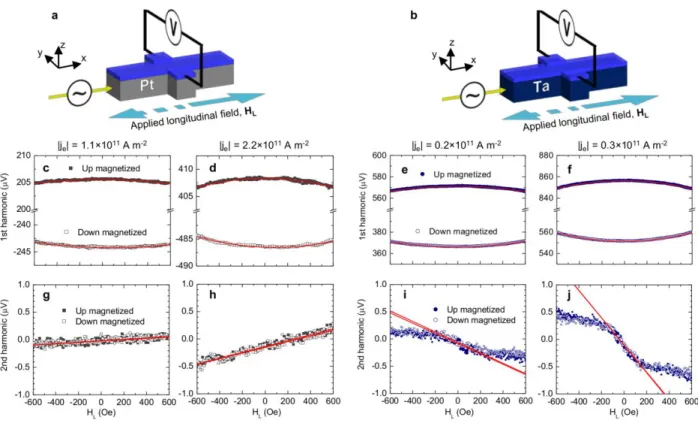
Figure 2 | Current-induced switching under a constant in-plane longitudinal field. a, Scanning electron micrograph of a Hall cross. b, c, Illustrations of Pt/CoFe/MgO (b) and Ta/CoFe/MgO (c) in the up magnetization state with the injected electron current and applied longitudinal field HL in the +x direction. Because of the combination of the current-induced Slonczewski-like torque (producing an effective field HSL) and the applied longitudinal field, up magnetization is stable in Pt/CoFe/MgO whereas it is unstable in Ta/CoFe/MgO. d, e, Out-of-plane magnetization Mz (normalized anomalous Hall signal) as a function of electron current density je under a constant HL in Pt/CoFe/MgO (d) and Ta/CoFe/MgO (e). The magnitude of HL is 500 Oe for Pt/CoFe/MgO (d) and 100 Oe for Ta/CoFe/MgO (e). When HL is reversed from +x (solid line) to –x (dotted line), the stable magnetization direction under a given current polarity reverses.
21
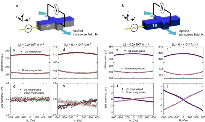
Figure 3 | Current-induced effective fields. a, b, Current-induced effective longitudinal field HSL, arising directly from the Slonczewski-like torque, as a function of electron current density je
(from AC excitation current amplitude) in Pt/CoFe/MgO (a) and Ta/CoFe/MgO (b). c, d, Current-induced effective transverse field HFL as a function of je in Pt/CoFe/MgO (c) and
Ta/CoFe/MgO (d). e, f, Illustration of the directions of the current-induced effective fields HSL and HFL in Pt/CoFe/MgO (e) and Ta/CoFe/MgO (f), when the magnetization is up and the electron flow is in the +x direction.
Figure 4 | Current-driven dynamics of chiral Néel domain walls. a, Illustration of left-handed chiral Néel domain walls in Pt/CoFe/MgO. The effective field HSL from the
Slonczewski-like torque moves adjacent up-down and down-up domains with velocity vDW in the same direction against electron flow je. b, Domain wall velocity as a function of electron current
density je, calculated using the one-dimensional model, with the spin Hall effect only (SHE only), the spin Hall effect and spin-transfer torque (SHE+STT), and the spin Hall effect and the
Dzyaloshinskii-Moriya interaction (SHE+DMI). The parameters used in this calculation are in the Methods section. c, d, Spin-torque efficiency for domain wall motion in Pt/CoFe/MgO under applied longitudinal field HL (c) and transverse field HT (d). e, f, Domain wall velocity at a constant current je = -3.0×10¹¹ A m-2 as a function of HL (e) and HT (f). g, h, Calculated domain wall velocity at je = -3.0×10¹¹ A m-2 as a function of HL (g) and HT (h) using the
22
Current-driven dynamics of chiral ferromagnetic domain walls
- Supplementary Information -
Satoru Emori1 , Uwe Bauer1, Sung-Min Ahn1, Eduardo Martinez2, Geoffrey S. D. Beach1*
1
Department of Materials Science and Engineering, Massachusetts Institute of Technology, Cambridge, Massachusetts 02139, USA
2
Dpto. Física Aplicada. Universidad de Salamanca, Plaza de los Caidos s/n E-38008, Salamanca, Spain
I. Measurement of the domain wall propagation field Hprop
A lithographically patterned 40-µm long, 500-nm wide magnetic nanowire is shown in Fig. S1a. Magnetization switching was measured using our custom scanning magneto-optical Kerr effect (MOKE) system1 with a ~3 µm focused laser beam placed at a fixed position midway along the nanowire. For each value of electron current density je injected through the nanowire, MOKE hysteresis loops were obtained under an applied out-of-plane field Hz with a triangular waveform of amplitude 150 Oe and frequency 12.5 Hz. After saturating the magnetic nanowire (e.g. uniformly magnetized down), a reverse domain (e.g. up) was nucleated using a 25-ns, 50-mA nucleation pulse just after the field zero-crossing. With the increasing Hz expanding the reverse domain, a domain wall (DW) propagated away from the nucleation line, and magnetization switching was detected by MOKE as the DW passed through the laser spot. After saturating the magnetic nanowire by domain expansion, Hz was swept in the other direction. For this side of field sweep, no DW was initialized so that magnetization switching occurred through domain nucleation at random locations in the nanowire. At a sufficiently large Hz, the
23
magnetization was saturated again in the initial direction. This measurement cycle was repeated at least 50 times and an averaged hysteresis loop was obtained to attain a sufficient signal-to-noise ratio and take into account the stochasticity of magnetization switching. The DW propagation field Hprop was taken as the field at which the normalized MOKE signal (Fig. S1b) crossed zero. As seen on the positive side of Hz in Fig. S1b, we observed a clear shift of Hprop even at small currents < 10 µA (|je| < 1010 A m-2), resulting in a linear correlation between Hprop and driving current as shown in Fig. 1 of the Letter. By contrast, no systematic variation in the nucleation field (switching field in the absence of an initialized DW) was observed with respect to current, as shown on the negative field side of Hz in Fig. S1b.
Figure S1 | a, Schematic of the domain wall propagation field measurement superposed on a scanning electron micrograph of a nanowire. The focused laser spot is placed halfway along the nanowire for magneto-opical Kerr effect (MOKE) measurements. b, Exemplary MOKE hysteresis loops on a Pt/CoFe/MgO device at under polarities of current densities (here, |je| = 0.07×10¹¹ A m-2). A domain wall is initialized only on the rising side of the positive applied field, so that here the positive coercive field is the DW propagation field while the negative coercive field is the reverse domain nucleation field.
Some data of DW propagation field were obtained with a high-impedance DC source outputting the current to drive DWs. However, initialized DWs were occasionally pinned around
24
the initialization line at larger magnitudes of driving current. We speculate that the voltage drop across the thin MgO layer might have locally modified magnetic anisotropy in the vicinity of the initialization line, through an effect similar to what was observed in Ref 2. To circumvent any issues associated with this pinning effect, we conducted most propagation field measurements in the following way: With the nanowire saturated (e.g. fully magnetized in the down direction), an out-of-plane field was ramped to ~20-30 Oe (less than the nucleation field) in 100 µs. While this field was maintained, a reverse domain (e.g. up) was nucleated with a current pulse in the initialization line. The field was maintained for another 50 µs to de-pin and drive the DW away from the initialization line by ~5 µm. After 1 ms, we then injected a current through the magnetic nanowire (output by a function generator with a rise-time of ~10 ns) and began sweeping the out-of-plane field at the same time. The difference in the extracted spin-torque efficiency depending on the measurement method was as much as ~20 %, but the polarity of the spin-torque efficiency did not change with the measurement method.
The DW motion data presented in Fig. 1 of the Letter were conducted at a constant substrate temperature of 308 K, maintained to within ±0.1 K with a thermoelectric module. The DW motion data under applied in-plane fields shown in Fig. 4 were not conducted on the thermoelectric module; the substrate temperature was within 295-300 K.
II. Current-driven domain wall motion for opposite senses of magnetization
A recent report by Haazen et al.3 on all-metal asymmetric Pt/Co/Pt stacks shows that current effectively promoted domain expansion or contraction, i.e. up-down and down-up DWs moved in opposite directions with respect to current under an in-plane longitudinal field. Current could displace DWs only under a sufficient in-plane longitudinal field that locked the
25
Néel wall configuration. Adjacent up-down and down-up Néel walls were expected to have opposite chiralities, with their internal magnetic moments oriented parallel to the longitudinal field, which would result in opposite directions of motion with respect to current. When the direction of the longitudinal field was reversed, the direction of motion for each DW was reversed. These results of current-driven DW motion in Pt/Co/Pt were attributed to the Slonczewski-like torque from the spin Hall effect.
By contrast, recent studies on Pt/Co/AlOx4,5 and Pt/Co/GdOx6 have reported up-down and down-up DWs moving in the same direction under current. We measured several different nanowires of Pt/CoFe/MgO and Ta/CoFe/MgO, and current-driven DW motion was also unidirectional in those devices irrespective of the magnetization sense across the DW. In particular, for both senses of magnetization across the DW (“Up-Down” and “Down-Up” DWs), the same trend was observed (Fig. S2): With electron flow in the same direction as field-induced DW motion, the propagation field increased in Pt/CoFe/MgO and decreased in Ta/CoFe/MgO. In other words, the motion of both Up-Down and Down-Up DWs was hindered in the direction of electron flow in Pt/CoFe/MgO and assisted in Ta/CoFe/MgO. The unidirectional motion of Up-Down and Down-Up DWs requires a Néel configuration with fixed chirality as discussed in the Letter and in Sections IX and X of this Supplementary document.
26
Figure S2 | a,b Direction of current-induced motion in Pt/CoFe/MgO and Ta/CoFe/MgO for an up-down domain wall (up domain expanding under an upward applied field) (a) and a down-up domain wall (down domain expanding under a downward applied field) (b). c,d Domain wall propagation field Hprop as function of driving electron current density je exhibiting the same trend for Up-Down (filled symbols) and Down-Up domain walls (empty symbols) in Pt/CoFe/MgO (c) and Ta/CoFe/MgO (d).
III. Velocity measurements of current-driven DWs
Current-driven DW velocity measurements were carried out by first driving a DW away from the nucleation line with the out-of-plane field pulse (as described in Section I) and then injecting the current to drive the DW. The field-driven DW velocity was measured by first
27
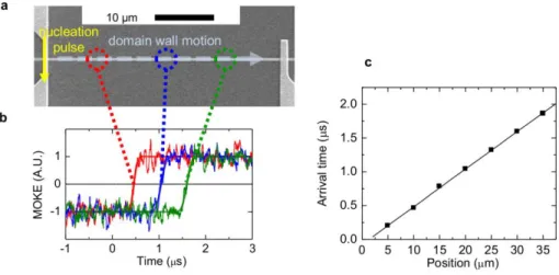
ramping the field to the setpoint driving level (because of the slow rise-time of the magnet ~100 µs) and then initializing a DW, which was subsequently driven to the other end of the nanowire by the constant driving field. The DW arrival time was extracted from MOKE signal versus time averaged over at least 50 measurement cycles, and the velocity was obtained by linearly fitting the plot of the arrival time at several positions along the nanowire, as shown in Fig. S3.
Figure S3 | a, Scanning electron micrograph of a 500-nm wide nanowire. The current pulse on the left initializes a domain wall, which is then driven to the right by an applied field or injected current. b, Magneto-optical Kerr effect signal showing magnetization switching due to domain wall propagation at different positions along the nanowire. c, Domain wall arrival time plotted against position along the nanowire. The domain wall velocity is extracted by linear fit.
IV. Domain wall velocity at higher current densities
In Fig. S4, we present the velocity of DWs up to electron current densities je larger than
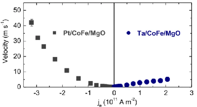
the range shown in Fig. 1 of the Letter. Interestingly, with |je| > 1×10¹¹ A/m2, the DW velocity is
higher in Pt/CoFe/MgO than in Ta/CoFe/MgO, despite the smaller spin-torque efficiency and spin Hall angle exhibited by Pt/CoFe/MgO. This paradox suggests that the DW velocity is not
28
necessarily an accurate metric of the current-induced torque, and that caution must be used when relying on velocity data alone to compare the current-induced torques in different materials. The origin of the paradox may be the difference in magnetization damping for these two structures: Pt-based magnetic thin films typically exhibit much stronger damping (with damping parameters ~0.1 or greater)7–9 than Ta-based ones (~0.01)10,11. The higher velocity in Pt/CoFe/MgO is then explained if the current-driven DW mobility scales with the damping parameter. Further
computational and experimental studies will elucidate the effect of damping on chiral Néel DWs driven by the Slonczewski-like torque.
Figure S4 | Domain wall velocity as a function of electron current density je in Pt/CoFe/MgO
and Ta/CoFe/MgO.
V. Measurement of current-induced switching
Magnetization switching was induced by 250-ms long current pulses injected in the longitudinal (x) direction of the cross (Fig. 2a). 250 ms after the current pulse was turned off, the out-of-plane component of the magnetization was measured from the anomalous Hall voltage using a 400-Hz low-amplitude (~109 A m-2) AC sense current and a lock-in amplifier. The out-of-plane magnetization was measured successively in this fashion by stepping through a range of current pulse amplitudes, producing hysteresis loops as shown in Fig. 2 of the Letter.
29
VI. Measurement of current-induced effective longitudinal field
Figs. S5a,b illustrate the measurement setup for determining the magnitude and direction of the effective in-plane longitudinal field HSL in a uniformly magnetized Hall cross. Two
lock-in amplifiers were used to measure the first and second harmonics lock-in the anomalous Hall voltage signal simultaneously. The frequency of the AC (sinusoidal) excitation current /2was 80 Hz. The measured second harmonic was set 90 degrees out of phase with respect to the first harmonic (see equations below). The applied in-plane longitudinal field HL from an electromagnet was swept from +600 Oe to -600 Oe and then back to +600 Oe quasistatically. An air-coil was placed directly beneath the sample substrate to apply a constant out-of-plane field of 32 Oe to keep the magnetization from switching.
The work by Kim et al.12 describes the derivation of the model used in our study to extract HSL produced by the Slonczewski-like torque. When the Hall cross is uniformly magnetized along the out-of-plane (z) direction, the AC excitation current generates an effective field along the longitudinal (x) axis, which modulates HL, i.e.
t H
H
HLtotal L SLsin .
This sinusoidal modulation of the longitudinal field results in an anomalous Hall voltage VAH of the form t V t V V VAH DC sin 2cos2 ,
where VDCis the component that does not depend on the frequency of the AC excitation, Vis
the in-phase first harmonic, and V2 is the out-of-phase second harmonic. The expressions for
30 2 2 2 1 D H I R V L O AH and L SL O AH H H D I R V2 2 2 ,
where RAH is the difference in the anomalous Hall resistance between the up and down magnetized states and IOis the amplitude of the AC excitation current. Dis a constant defined by the out-of-plane uniaxial anisotropy constant KU , saturation magnetization M , and applied S out-of-plane field Hz : D
2KU /MS
4MS Hz . The ± in front of the equations correspond to the up (+ z) magnetized and down (- z) magnetized states, respectively. The ratio of the first derivative of V2to the second derivative of Vis taken to solve for HSL: 2 2 2 2 L L SL dH V d dH dV H .
In the above expression, the sign of HSL indicates the direction of HSL (+x or –x) when
conventional current is positive, i.e. in the + x-direction. In the Letter, we discuss the directions of HSL when electron flow is in the + x-direction (conventional current in the –x direction).
Therefore, the appropriate expression for HSL in the Letter has the opposite sign.
2 2 2 2 L L SL dH V d dH dV H .
There are a few key assumptions that go into this model12. (1) The Hall cross is uniformly magnetized. (2) The tilting θ of the out-of-plane magnetization is small (small angle approximation sinθ ≈ θ). (3) The magnetization is not tilted in the transverse direction, although in general current can generate a torque that pulls the magnetization in the transverse direction as well.
31
Exemplary data of V and V2are shown in Figs. S5c-j. As expected, V data for both
Pt/CoFe/MgO and Ta/CoFe/MgO vary quadratically with HL as the magnetization tilts away from the perpendicular axis. We observed different offsets in Vin various devices due to a voltage drop from < 0.1% of excitation current flowing in the transverse direction of the Hall cross (≈ 17 kΩ for Ta/CoFe/MgO, ≈ 5 kΩ for Pt/CoFe/MgO). The maximum magnetization tilting at 600 Oe of applied longitudinal field is ≈ 20 o (0.35 rad) in Ta/CoFe/MgO and ≈ 10 o (0.17 rad) in Pt/CoFe/MgO. The variation of V2is linear with respect to longitudinal field in
Pt/CoFe/MgO, consistent with the model described above.
Figure S5 | a,b Schematics of the anomalous Hall voltage measurement to determine the effective longitudinal field HSL arising from the Slonczewski-like torque in Pt/CoFe/MgO (a) and
in-32
plane longitudinal field HL in Pt/CoFe/MgO (c,d) and Ta/CoFe/MgO (e,f). g-j, Second harmonic
of the anomalous Hall voltage as a function of HL in Pt/CoFe/MgO (g,h) and Ta/CoFe/MgO (i,j).
However, for Ta/CoFe/MgO, different linear slopes of V2were observed, with a larger
slope for |HL| < 100-200 Oe and a reduced slope for |HL| > 100-200 Oe. We observed this
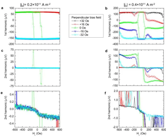
behavior in all measured Ta/CoFe/MgO Hall crosses. To explore the origin of this behavior, V and V2were measured under different constant bias out-of-plane fields as shown in Fig. S6. For
a small excitation current (Figs. S6a,c,e), magnetization switching was observed and V2 diverged around HL = 100 Oe under zero out-of-plane field. The switching and divergence were suppressed under nonzero out-of-plane fields, although the transition in the V2 slope remained. At an even higher excitation current amplitude (Fig. S4b,d,f), diverging features at
L
H ≈ 100 Oe could no longer be suppressed by out-of-plane field. Although we do not have a complete explanation for the origin of these features, we can attribute the transition in the V2 slope appearing at HL≈100-200 Oe to the formation of a multi-domain state (i.e. deviation from uniform magnetization) or the onset of instability in the magnetization direction. For example, the combination of a sufficient longitudinal field and excitation current could possibly destabilize the magnetization around the edges of the Hall cross, where perpendicular magnetic anisotropy might be weaker. In extracting HSL, we took the steeper slope of V2around zero longitudinal field, where the out-of-plane magnetization was expected to be uniform and HL is not large enough to drive the instability. We also limited the range of excitation current amplitude (Fig. 4 main text) so that both Vand V2 data could be fit quadratically and linearly, respectively, over a sufficient range of HL.
33
The estimated Hall angle in Ta based on HSL ≈ -200 Oe/10
11
A m-2 presented in the main text (Fig. 4) is extraordinarily large at -0.25. We further note that an even largerHSL of around -400 Oe/1011 A m-2 was observed for another Ta/CoFe/MgO Hall cross. This suggests that our results deviate from the ideal extraction of HSL described in Ref. 12, likely due to the instability in the magnetically soft Ta/CoFe/MgO (with relatively weak perpendicular magnetic anisotropy). Regardless of the deviation in the magnitude, the slopes of V2 are clearly opposite in Pt/CoFe/MgO and Ta/CoFe/MgO. We emphasize that the directions of the Slonczewski-like torque, and hence the resulting effective fields, in Pt/CoFe/MgO and Ta/CoFe/MgO are opposite.
Figure S6 | a,b, First harmonic of the anomalous Hall voltage in Ta/CoFe/MgO at several different out-of-plane bias magnetic fields. c-f, Second harmonic of the anomalous Hall voltage
34
in Ta/CoFe/MgO at several different out-of-plane bias magnetic fields. Close-ups of the slope transition are also shown (e,f).
VII. Measurement of current-induced effective transverse field
The measurement of the current-induced effective transverse field HFL was carried out in
the same fashion as the measurement of HSL, except with the applied in-plane field HT in the
transverse (y) direction. Based on Ref. 12, the expressions for the first and second harmonics of the anomalous Hall voltage are
2 2 2 1 D H I R V T O AH and T FL O AH H H D I R V2 2 2 .
The resulting expression for HFL is then
2 2 2 2 T T FL dH V d dH dV H .
In the Letter, we again discuss the directions of HFL when electron flow is along +x, so the appropriate expression for HFL is
2 2 2 2 T T FL dH V d dH dV H .
35
Figure S7 | a,b, Schematics of the anomalous Hall voltage measurement to determine the effective transverse field HFL in Pt/CoFe/MgO (a) and Ta/CoFe/MgO (b). c-f, First harmonic of
the anomalous Hall voltage as a function of applied in-plane transverse field HT in Pt/CoFe/MgO
(c,d) and Ta/CoFe/MgO (e,f). g-j, Second harmonic of the anomalous Hall voltage as a function of HT in Pt/CoFe/MgO (g,h) and Ta/CoFe/MgO (i,j).
The opposite directions of HFL observed in Pt/CoFe/MgO and Ta/CoFe/MgO may arise
from the Rashba effect, although we cannot conclude whether there is any difference in Pt/CoFe/MgO and Ta/CoFe/MgO that may induce opposite polarities of the Rashba field. A more straightforward explanation, as pointed out in the Letter and in Ref. 13, is that the observed HFL may be an artifact of the Slonczewski-like torque in the presence of an applied transverse
36
VIII. Current-driven DW motion in various out-of-plane magnetized ultrathin layered structures
In this present work, we discuss the anomalously efficient current-driven DW dynamics in heavy-metal/ferromagnet/oxide structures. Similar DW dynamics have been observed in Pt(15 Å)/Co(3 Å)/Ni(7 Å)/Co(1.5 Å) capped by a TaN overlayer14. This suggests that insulating materials other than oxides can be used for efficient motion of chiral DWs propelled by the Slonczewski-like torque from the spin Hall effect. Furthermore, Ref. 15 reports multiple DWs moving uniformly against electron flow in an ultrathin structure of Pt/Co/Pt with different thicknesses for Pt underlayer and overlayer. Many studies have also shown current-induced DW displacement in Co/Pt multilayers, whereas others have reported no such current-induced effect other than Joule heating. The recent study by Haazen et al.3 reports DW displacement in asymmetric Pt/Co/Pt due to the spin-Hall effect only when a finite longitudinal magnetic field is applied, in contrast to the report16 of systematic current-induced DW displacement in similar structures without any applied longitudinal field.
This wide discrepancy may arise from the requirement for current-induced DW motion governed by the spin Hall effect: asymmetry in the interfaces is necessary to stabilize a Néel wall through the Dzyaloshinskii-Moriya interaction. Recent studies17,18 have been shown that, in Pt/Co/Pt, the magnetic anisotropy arising from the bottom Pt/Co interface is significantly stronger than that from the top Co/Pt interface. On the other hand, the relative strengths of interfacial anisotropy may vary in structures with different underlayers, deposition conditions, and post-deposition treatment processes (e.g. ion irradiation). Such subtle interfacial differences could have resulted in the disparate efficiencies of current-induced DW displacement in Co/Pt-based structures.
37
More generally, the interface between the ferromagnet and the overlayer (in addition to the interface between the ferromagnet and the underlayer) may also influence the efficiency of current-driven DW motion. For example, according to our recent work on Pt/Co/GdOx6, disrupting the Co/GdOx interface with a 4-Å thick Pt layer nearly halved the spin-torque efficiency, compared to the equivalent structure with an uninterrupted Co/GdOx interface. This Pt dusting layer was likely not continuous, and its thickness was significantly smaller than the spin diffusion length in Pt (≈ 1.4 nm)19. Therefore, the Pt dusting layer did not generate a Slonczewski-like torque that counteracted the torque from the Pt underlayer; the reduction in the spin-torque efficiency instead was caused directly by the altered Co/GdOx interface. Although the Dzyaloshinskii-Moriya interaction (DMI) in an ultrathin ferromagnet has been reported to arise from its interface with a nonmagnetic heavy metal20,21, it is possible that a ferromagnet/oxide (or ferromagnet/insulator) interface contributes to the DMI as well.
IX. Micromagnetic description of torques
The general form of the Landau-Lifshitz-Gilbert equation including the spin-transfer torque (STT) and the Slonczewski-like torque (SLT) from the spin Hall effect (SHE) is
SHE SLT STT eff t m m H m t m 0 , (1)
where m M /Ms is the normalized local magnetization ( m 1), and 0 2.21×10⁵ m/(As) is the gyromagnetic ratio. The terms on the right-hand-side represent the different torques on the local magnetization.
The first term is the precessional torque,
eff precesion m H 0 , (2)
38
which describes the precession of the magnetization around the local effective fieldHeff
. This effective field includes exchange, demagnetizing, anisotropy and external field contributions. In the present analysis, a high perpendicular magnetic anisotropy (PMA) strip is considered with the easy axis pointing along the z-axis.
The second term is the damping torque,
t m m damping , (3)
where is the dimensionless Gilbert damping parameter. This torque describes relaxation of the local magnetization m toward its equilibrium, aligned parallel to the local effective field Heff .
The third term is the spin-transfer torque (STT) that includes both adiabatic and non-adiabatic contributions:
u
m b m
u
m bJ x J x STT (4)where the applied current is ja jaux. Note that “current” ja here denotes conventional current
(flow of positive charge carrier), which is in the opposite direction with respect to the electron flow je in the Letter. The coefficient bJ is given by
a s B J j eM P b (5)
and is the dimensionless non-adiabatic parameter. B 9.2741024J/T is the Bohr magneton and e1.61019C is the electron charge.
Finally, the last term is the Slonczewski-like torque (SLT) due to the Spin-Hall effect (SHE), which according to Refs. 22 and 23, is given by
y z s a SH SHE SLT m u L eM j m 0 0 2 , (6)
39
where SH is the spin-Hall angle, and Lz is the thickness of the ferromagnetic sample, and
Js 10 × 1.054 -34
is the Planck's constant. This SHE torque (Eq. 6) can be re-written in a similar form to the standard precession torque (Eq. 2) as
SHE SHE SLT m H 0 (7)
where HSHE is the spin Hall effective field, which is the term between brackets in (Eq. 6), and therefore can be written as:
y z s a SH SHE m u L eM j H 0 2 (8)
The direction of this effective field depends on the internal magnetization direction of the Néel DW (Right or Left) and on the magnetization directions of the domains on left and right sides of the DW. This effective field then determines the direction of DW motion (DWM). See discussions below.
X. Direction of domain wall motion (DWM)
In a thin ferromagnetic strip with high PMA along the z-axis, there are two possible senses of magnetization across a DW: (a) Up-Down and (b) Down-Up. These are depicted in the following Fig. S8, along with the coordinate system.
Figure S8 | DW configurations depending on the magnetization on either side of the DW: Up-Down (a) and Up-Down-Up (b).
DW DW
x>0 y>0
(a) Up-Down (b) Down-Up
40
We first consider the simplest case of DW motion driven solely by an out-of-plane (z) magnetic field
z ext
ext H u
H , (9)
where Hext can be positive (Hext Hextuz,with Hext>0, so pointing along the Up domain) or
negative (Hext Hextuzwith Hext>0, so pointing along the Down domain). No current is considered in this case so that the STT (Eq. 4) and SLT (Eq. 6) vanish. The combination of the precessional and damping torques drives the magnetization to the direction of Hext. Therefore, a
domain oriented in the direction of Hext grows. As summarized in Fig. S9, with Hext> 0 the
Up-Down DW propagates to the right (x > 0) and the Up-Down-Up DW propagates to the left (x < 0); with Hext< 0 the Up-Down DW propagates to the left (x < 0) and the Down-Up DW propagates
to the left (x > 0). The magnetization configuration of the DW itself, whether it is Bloch or Néel, does not affect the direction of motion. Thus, two adjacent DWs (one Up-Down and the other necessarily Down-Up) in a magnetic strip propagate in opposite directions under the application of a uniform out-of-plane field (Eq. 9). This feature may not be desirable in many device applications (e.g. DW shift register or “racetrack memory”), because uniform shifting of adjacent digital bits encoded as magnetic domains is required.
41
Figure S9 | Direction of DWM under positive and negative out-of-plane field for the Up-Down (a) and Down-Up (b) configurations. The direction of field-driven DWM does not depend on the internal magnetization configuration of the DW.
Contrary to the field-driven case, the sense of the current-driven DWM due to the SHE depends on the internal DW magnetization, because the SLT from the SHE depends on the magnetization direction (Eq. 6). The SLT cannot exert a torque on a Bloch DW, whose internal magnetization points along the transverse (y) axis, i.e. muy 0 in Eq. 6. We therefore focus on the SLT acting on Néel DWs, whose internal magnetization is oriented along the longitudinal (x) axis and four possible configurations, as illustrated in Fig. S10.
DW DW
x>0 y>0
(a) Up-Down (b) Down-Up
z>0 z ext ext


![Figure S10 | DW configurations: Up-Down domains with Neel-Right DW [U-NR-D] (a), Up- Up-Down domains with Neel-Left [U-NL-D] (b), Up-Down-Up domains with Neel-Right [D-NR-U] (c), and Down-Up domains with Neel-Left [D-NL-U] (d)](https://thumb-eu.123doks.com/thumbv2/123doknet/14531192.533641/43.918.221.702.109.463/figure-configurations-domains-right-domains-domains-right-domains.webp)
