THÈSE
En vue de l’obtention duDOCTORAT DE L’UNIVERSITÉ DE TOULOUSE
Délivré par : l’Université Toulouse III – Paul SabatierDiscipline ou spécialité : Génie Mécanique
Présentée et soutenue par Farid MIAH
Sur
Numerical and Experimental Analysis of CFRP Machining Process in Orthogonal
Cutting
Soutenue le 17 janvier 2020 devant le JURY composé de :
Olivier CAHUC Professeur des Universités, Universités de Bordeaux (Examinateur) Mohamed EL-MANSORI Professeur des Universités, ENSAM Aix-en Provence (Rapporteur) Mohammed NOUARI Professeur des Universités, Universités de Lorraine (Rapporteur) Xiaojing GONG Professeure des Universités, IUT de Tarbes (Examinatrice) Yann LANDON Maitre de Conférences, HDR, Universités de TOULOUSE (Invité) Frederic LACHAUD Professeur, ISAE-SUPAERO (Directeur de thèse) Emmanuel DE LUYCKER Maitre de Conférences, ENIT de Tarbes (Co-directeur de thèse)
Ecole doctorale : Mécanique, Energétique, Génie Civil & Procédés (MEGeP) Unité de recherche : Institut Clément Ader
Acknowledgment
Sometimes I look back at these last three years of my doctoral school and I wonder while I feel that these three years have passed by as like three days. I become ravenously hungry to discover more knowledge while I ask myself if I could bring to light a drop amount of information in machining from within oceanic scale of machining knowledge. My experience at Institut Clement Ader (ICA) laboratory has been nothing short of amazing. I have been given unique research opportunities…. and taken advantage of them. I am indebted to many people for making the time for working my PhD an unforgettable experience.
I am very grateful to my advisors Frederic LACHAUD and Emmanuel DE LUYCKER, two incredible persons, who have supported me patiently not only by providing the research assistance and planning, but also the freedom I needed to move on through the rough road to finish this thesis. Frederic’s remarkable supports in numerical modelling, which include incredible new ideas to find out solutions, played a significant role in the advancement of my PhD. I sincerely acknowledge the patience of Emmanuel he showed to aline my research work with research goals, to guide me on scientific analysis, scientific report writing, presentation making and so on. To work with both of them has been a real pleasure to me. Besides, I am grateful to my external supervisors, Yann LANDON and Robert PIQUET, for their support and discussions in this thesis.
I would like to thank Abdallah BOUZID, engineer at ICA, for his generous assistances during the machining experiments at the workshop. I remember while we encountered any problem during the tests he used to tell me “there is no problem but only solutions, because problem does not exist”. I am also thankful to Olivier CHERRIER and Alexandre CHARDONNEAU, two engineers of ICA, who always lent their helpful hands for the installation and operation of high speed cameras. Furthermore, I have been very privileged to work with my colleagues at the laboratory; notably, Benoit MONTAGNE who was my officemate, Jean-Emmanuel CHAMBE, Agathe JAILLON, Akshay HEJJAJI, Malek BENAISSA and many other. There is no way I can ever list all of the amazing people who got me this far. They are truly amazing people. I learned a lot from them about research, how to tackle new problems and develop techniques to solve them. The work on this thesis was financed by French government. I hereby show my humble gratitude to the French government for the finance which permitted me to have this extraordinary PhD research experience.
Finally, I think of my late father who, if were alive today, would be highly delighted by my today’s acquirement. I specially thank my mother, my brothers and sisters and all other family members for their infinite support in all my pursuits. I exceptionally thank my brother Mustofa SARWAR and his spouse Shanta AKTER who have given unconditional care and support in every way throughout my whole study life. I would not have made it this far without their supports.
Outline
The Composite materials, including CFRP (Carbon Fiber Reinforced Polymer), are increasingly used in aeronautics and automotive as these materials are capable of playing a unique role in industrial applications by their outstanding lightweight properties. In the latest model of Airbus, A350-900, the CFRP content is more than 50% in weight. This extensive use of composite structures is currently raising many complications in the machining processes as those materials are made with multiple phase microstructures which are accountable for poor machining quality and undesired damages, e.g. delamination, crack generation. Along with some other machining operations, drilling is the most common machining operation for CFRP processing; for example, around 1.2 million bores are required in one Airbus A350 for rivet joining which primarily needs drilling operation. Therefore, it is believed that the fundamental analysis of cutting mechanism and chip formations process of CFRP can help to increase the process effectiveness, which will result reduced defects in the machined parts.
On that account, a thesis was already done by [Blanchet, 2015] at Institut Clement Ader which focused to a simplified cutting technique called orthogonal process. Nevertheless, many particular questions remained unanswered in this process as there are many process parameters which play distinct significant role on the quality of manufactured parts. The present thesis is thematically connected to the work of [Blanchet, 2015]. It seeks to better understand the fundamental physical technique involved in the process by combined numerical and experimental study, and how certain cutting parameters affect the machining quality. To this aim, initially the focus was made to the strain field generation in the workpiece while the tool cuts the materials. At the same time, an in-depth observation was made on how chips are formed at 0°, 45°, 90° and 135° fiber orientations. For that study, a micro-mechanical model was developed distinguishing the properties of fiber and matrix separately. A cohesive interface property (zero volume) was introduced in fiber-matrix interface. Both the experimental and numerical observations clearly showed the physics of chip formation mechanism.
Following that, the influences of cutting depth, which is an important process variable, to (i) cutting and thrust forces, (ii) surface roughness, (iii) subsurface damage and, (iv) chip shape and size were studied. The studies were carried out by experimental tests as well as by a macro-mechanical model which was developed with equivalent homogeneous material (EHM). Besides, the X-ray tomography tests revealed the machining induced interply delaminations and inner crack generation in the workpiece.
The definition of a minimum cuttable depth, classical for metal cutting, still does not exist for CFRP in literature. Therefore, an experimental observation was made to find out the minimum cuttable depth below which the material does not get cut smoothly over the whole surface. At the end, this research work has been finished by a preliminary study on cutting tool wear mechanism.
Content
Context of the Research ... 11
I.I. Introduction ... 11
I.II. Defects in CFRP Machining in Orthogonal Cutting ... 14
I.III. Goals of the Research ... 15
Chapter 1: State of the Art ... 19
1.1. Literature Review ... 21
1.1.1. Orthogonal Cutting in Machining ... 21
1.1.1.1. Mechanics of Orthogonal Cutting ... 22
1.1.2. Findings on Cutting Parameters and Generated Defects ... 25
1.1.2.1. Cutting Operation and Variables ... 25
1.1.2.2. Machining Induced Defects ... 41
1.1.3. Various Developed Models in CFRP Machining... 47
1.1.3.1. Micro-mechanic Models ... 47
1.1.3.2. Macro-mechanic Models ... 59
1.1.3.3. Analytical Models ... 66
1.1.4. Summary of Literature Study ... 72
1.2. Conclusion ... 73
Chapter 2: Developed Models, Strain Field Analysis and Chip Formation Mechanisms ... 75
2.1. Experimental Process ... 77
2.1.1 Machine Setup ... 77
2.1.1.1. Machine Operation and Its connections ... 78
2.1.1.2. Cutting Parameters and Related Configurations ... 79
2.1.2. Cutting Tool Selection ... 80
2.1.3. Workpiece Preparation ... 81
2.2. Developed Models ... 83
2.2.1. Micro-mechanical Model ... 83
2.2.1.1. Boundary Conditions and Meshes... 85
2.2.1.2. Interaction Properties ... 86
2.2.1.3. Material’s Property and Failure Criteria ... 91
2.2.2.1. Geometry and Boundary Conditions ... 93
2.2.2.2. Contact Modeling ... 94
2.2.2.3. Meshing, Adaptive Meshing and Distortion Control ... 94
2.2.2.4. Failure Criteria ... 96
2.3. Strain Measurement Process ... 100
2.3.1. Experimental Strain Measurement Process ... 100
2.3.2. Numerical Strain Measurement Process ... 104
2.4. Strain Field Analysis ... 106
2.4.1. Experimental Results ... 106
2.4.2. Comparison of Numerical and Experimental Results ... 110
2.5. Chip Formation Mechanism in Orthogonal Cutting of CFRP ... 113
2.5.1. The Course of Chip Formation ... 114
2.6. Conclusion ... 124
Chapter 3: Effects of Cutting Depths ... 125
3.1. Configurations of Analysis ... 127
3.1.1 Machine Setup ... 127
3.1.2. Materials and Cutting Conditions ... 127
3.1.3. Measurement Techniques ... 128
3.1.3.1. Force Measuring Procedure ... 128
3.1.3.2. Roughness Measuring Technique ... 130
3.1.3.3. Chip’s Dimensions Measuring Technique ... 131
3.2. Effects to Machining Forces ... 132
3.2.1. Results and Discussion ... 133
3.2.1.1 Cutting Force ... 133
3.2.1.2. Thrust Force ... 135
3.2.2. Force When the Tool Touches the Workpiece ... 137
3.3. Effects to Surface Roughness ... 139
3.3.1. Results and Discussions ... 139
3.4. Effect to Subsurface Damage ... 144
3.4.1. Crack Generation and Propagation ... 144
3.4.2. Subsurface Damage Analysis by X-ray Tomography ... 149
3.5.1. Chip’s Length ... 157
3.5.2. Chip’s Height and Width ... 159
3.6. Conclusion ... 161
Chapter 4: Tool Wear and Minimum Cutting Depth for Continuous Cut ... 163
4.1. Minimum Cutting Depth for Continuous Cut ... 165
4.1.1. Experimental Procedure ... 165
4.1.2. Result Analysis ... 168
4.1.3. Conclusion, Difficulties and Perspectives ... 175
4.2. Tool Wear Mechanism ... 176
4.2.1. The Tool and the Wear Measuring Procedure ... 177
First Test ... 177
Second Test ... 180
4.2.2. Results Analysis ... 181
4.2.2.1. First Test ... 181
4.2.2.2. Second Test ... 184
4.2.3. Conclusion and Perspectives ... 186
Global Conclusion and perspectives ... 187
References ... 189
τ : Equivalent shear stress τlim : Limiting shear stress ԑ : Lagrange strain έ : Strain rate ԑ̅ : strain vector
δ : Displacement in cohesive interface α : Rake angle
γ : Clearance angle µ : Friction coefficient σ : Cauchy stress σy : Yield stress σ0 : Initial yield stress σn : In-plane normal stress σf : In-plane normal strength ɳ : Cohesive property parameter ф : Shear angle
Ø𝑖 : Damage evolution variable p̿ : Stiffness matrix
∆n : Normal displacement b : Cohesive sliding resistance B : Hardening modulus
C : Strain rate sensivity coefficient CFRP : Carbon Fiber Reinforced Polymer D : Damage variable
EHM : Equivalent Homogeneous Material e˙p : Plastic strain rate (s -1)
E : Modulus of elasticity Ep : Plastic hardening modulus Etan : Tangent modulus
F : Force
FEM : Finite Element Analysis Gr/Ep : Graphite/Epoxy
: Critical fracture energy in normal direction : Critical fracture energy in first shear direction : Critical fracture energy in second shear direction ICA : Institut Clement Ader
Kn : Normal stiffness component Ks & Kt : Shear stiffness components m : Thermal softening coefficient n : Hardening coefficient
P : Contact pressure / the effective plastic strain T : Temperature of the work material (K)
𝑇𝑒𝑓𝑓0 : Effective traction at damage initiation tn : Normal contact stress
ts & tt : Shear contact stresses T0 : Room temperature (K)
X2 : Angle between fiber orientation and cutting direction Xt : Longitudinal tensile strength
Yt : Transverse tensile strength
𝐺
𝑛𝐶𝐺
𝑠𝐶Context of the Research
I.I. IntroductionSince the industrial revolution the manufacturing technologies have been the driving force behind modern economies. The machineries and structures which we need at every aspect of our life are created by these technologies. Today the technologies have become more sophisticated by the advances of computer and material sciences which increased our ability to develop predictive capability and optimization for various applications. Metal cutting processes are some of the oldest widely used methods which are used to give a particular shape to a metal piece and these processes are involved in manufacturing process, whether directly or indirectly, of most of the items we use today [Altintas, 2012] [Limido et al., 2011]. In machining, to understand the mechanics of chip formation of metal machining much work has been done over the past century, and the same techniques have been used to study the composites machining but no much success was found [Ahmad, 2009]. Moreover, the numerical modeling of composites cutting is still poorly developed [Cantero et al. 2012].
The necessity of good understanding of composites machining is becoming highly important as the composite materials, including CFRP (Carbon Fiber Reinforced Polymer), are increasingly used in aeronautics and automotives because of their high mechanical strength with respect to the density, good resistance to corrosion and to fatigue. During the last decade the demand for composite materials has increased significantly. In 2010 the global carbon fiber demand was 33 thousand tons, and it is estimated at 89 thousand tons for 2020, which is mostly for aerospace & defense (30%), and then automotive, molding & compound and wind turbines, Fig. I.I, [Mark H., 2014]. In addition, the European regulations to reduce the CO2 consumption and pushing for lightweight manufacturing are playing a significant role on the growth demand these days. The Airbus model A350 XWB already used a CFRP content of 50% [Altaire, 2012], Boeing 787 Dreamliner used 53% for outer skin [Fay B., 2012] [Boeing AEOR]; similarly, the fighter jet Eurofighter used 40% composite in weight [Smith and al., 2013], Fig. I.II.
This extensive use of composite structures is presently raising a lot of complications in their machining processes. Along with some other machining operations, drilling is the most common machining operation for CFRP processing; for example, around 1.2 million bores are required in one Airbus A350 for rivet joining which primarily needs drilling operation. But composite materials are not homogeneous, and the chip formation process in machining composite laminates is significantly different from that in machining of metals, e.g. milling, turning and drilling. According to [Lasri et al., 2009] the machining of fiber reinforced polymer (FRP) materials differs from machining conventional metals and their alloys due to the heterogeneity and anisotropy of FRP materials. [Liu et al., 2012] noted composite laminates are regarded as hard-to-machine materials, which results in low machining efficiency and undesirable
machining-induced delamination. Moreover, in cutting mechanism of composites, fiber orientation, cutting depth, rake and clearance angles play significant role on the cutting forces. The surface roughness of the newly generated surface varies depending on the process variables. The shape and size of the chip depends not only on depth of cut but also on the fiber orientation and rake angle. Overall, composite machining draws many questions to be solved in order to increase the quality of machining.
It is believed that the fundamental analysis of cutting mechanism and chip formations process of CFRP material can help increasing the machining efficacy. Orthogonal cutting is a type of material cutting technique in which the cutting edge of a wedge shape cutting tool is perpendicular to the direction of the tool motion. This cutting process involves the systematic removal of layers of material in the form of chips from a workpiece by the action of a wedge shaped cutting tool. This process directly refers to Turning, External Threading, Grinding and Filling, and can be used indirectly to make reference to Milling and Drilling (a chart of most common machining processes has been shown in Diag.1.1.1). Milling and Drilling are considered as oblique processes of which the tool has minimum 3 angles, and that is why analyzing the machining phenomenon, machining quality and more especially the machining induced defects in manufactured part is difficult. In drilling, visual inspection inside of hole is very complex; as a result it becomes difficult to identify the machining induced defects inside a hole. Moreover, for numerical analysis, the 3 angles of cutting tool obliges to make model in 3D which also amplify the complexity of the model.
Fig. I.I: Global demand for carbon fiber (a) trend of demand (in thousand tons), (b) demand by application (in 20103), [Mark H., 2014].
Recently the research activities in orthogonal cutting of composite laminates have been increased since it has been recognized that fundamental knowledge of orthogonal machining process can help in the solution of many particular production problems of composite parts. The simpler conditions of orthogonal machining in studying chip formation permits to gather knowledge about different components like chip shape and size, shear stress and strain in chip, friction conditions, cutting forces, cutting temperatures etc. [Klinkova et al., 2011].
In this context, a PhD research was done by Blanchet [Blanchet, 2015] in the same laboratory and defended in 2015. His PhD disclosed some process parameter’s influences to machining quality in orthogonal cutting of CFRP along with defining cutting tool geometry and test bench for experimentation. However, many physical phenomenon remains unrevealed, especially the mechanics of chip formation, cutting depth influence, machining induced damages, tool sharpness loss etc. which deserves inclusive research. Aiming at those problematics this present research has been carried out. The physical phenomenons have been analyzed experimentally along with numerical simulation. For the experimentations an existing experimental bench developed by [Blanchet, 2015] has been used. Concerning numerical analysis there are some methods exists to simulate the cutting process. FEM method is well-known for cutting
Fig. I.II: Materials used in the outer body of (a) Airbus A350 XWB [Altaire, 2012], (b) Boeing 787 Dreamliner [Fay B., 2012] [Boeing AEOR], (c) Eurofighter [Cephas and Luling, 2017].
simulations, and so FEM is chosen for current analysis. Some researchers (found in literature) have used SPH method too and argued that this method gives better result compare to FEM as it is a meshless method.
Regarding the microstructure development for CFRP in FEM machining two approaches have been implemented which are mechanical and macro-mechanical approaches. The micro-mechanical describes the local material microstructure by two separate phases, fiber and epoxy, and introduces distinctive material properties. This approach gives better understanding of micro mechanics for fiber damage, failure, surface roughness, chip formation and separation etc. On the other hand, the macro-mechanical approach provides larger scale informations using homogenized microstructure with equivalent anisotropic properties. This approach has the limitations of homogenized methods in the case of CFRP machining but is capable of evaluating macroscopic data such as the cutting forces.
Having said that, this research in orthogonal technique not only will help to well understand the cutting physics in turning, external threading, grinding and filling but also bring up the phenomenon and physics of drilling and milling of CFRP.
I.II. Defects in CFRP Machining in Orthogonal Cutting
Composite laminates are regarded as hard-to-machine materials, which results in low cutting efficiency and undesirable delamination [Liu et al., 2012].Most of the defects in CFRP machining are arising due to the multiple phase characteristics of this material. The high abrasive behavior of this material is mostly responsible for tool wear which not only affects the quality of the machined parts but also increases the manufacturing time and cost (cutting tools are expensive and changing tool because of wear is time consuming).
According to [Haitao L. et al., 2019], machining damage occurs on the surface of CFRP composites during the processing. Some defects, mentioned in literatures, are: delamination, surface roughness, spring back, tool wear, crack generation and propagation, deformation of material, fiber crushing, surface burning, and scratching [Dref, 2014], [Guegan, 1994], [Konig and Gr ab, 1989], [Ghidossi, 2003], [Rahme, 2008], [Lazar and Xirouchakis, 2011], [Gaitonde et
al. 2008], [Liu et al., 2008].
Delamination can be of many types like pill up, push down, interlaminar etc. One of the most critical defects in CFRP machining is interlaminar delamination which is very difficult to identify. The main reason for interlaminar debonding between fiber and matrix is the high strength of fibers in comparison to the matrix one [Shchurov et al., 2016]. It may be possible to minimize the scale of most of the defects but might not be possible to resolve all absolutely.
I.III. Goals of the Research
In order to control the quality of machining in composite laminates and determine its influence on the mechanical behavior, it’s necessary to better understand the cutting processes for these materials. The importance of these materials brought its cutting processes in the shade of research which is being focused more and more with time. Some remarkable research work on orthogonal cutting have been found through the literature study but many physical phenomenon, responsible for poor quality of machining, have remained unanswered.
Fig. I.IV: Machining induced defects; (a) Surface cavities [Changying et al., 2016], (b) Crack generation [Blanchet, 2015]
[Blanchet, 2015] carried out a numerical and experimental study at the present laboratory focusing to the effect of different cutting speeds and positive and negative rake angles to the cutting efforts and surface roughness of machined parts. Nevertheless, a fundamental understanding of chip formation mechanism and the influences of some cutting variables are still untouched. The importance of understanding the influences of cutting variables in orthogonal cutting of CFRP is crucial because of their significant influences to the machining quality.
For this purpose in this research we will firstly analyze the strain field generation in the workpiece during cutting. Then we will focus on the stress-strain propagation and the fiber-matrix debonding phenomenon of the process. This analysis will give a fundamental understanding of the chip formation mechanism as well as a broad overview of the reason of surface roughness on newly generated cut surface.
[Nayak et al. 2005] and [Zitoune et al. 2005] mentioned that cutting depth affects the morphology of chip. If the morphology of chip is changed then the surface state of the newly generated surface as well as other relevant phenomenon will be affected too. So it is necessary to understand the influence of cutting depths. For this reason the effects of different cutting depths (from very low to high) to the cutting efforts, surface roughness, crack generation and propagation will be analyzed. Additionally, the generated chips’ size and shape at different depths will be studied.
When the concern is cutting depth, a question becomes apparent which is: what is the minimum cuttable depth? The minimum cuttable depth in CFRP machining is more complex than metallic materials as CFRP are made with multiple phases and fiber orientation. Regarding this fact, an experimental study will be carried out in order to see what is the minimum depth a tool can cut at different fiber orientations of CFRP.
The issue of subsurface damage in the workpiece is an important concern. As the subsurface damages are not openly visible, it is difficult to identify those defects inside, including inter-laminar delamination. So in order to study the subsurface damages the test specimens will be brought under X-ray tomography. It is expected that tomography tests will reveal the potential subsurface damages which are generated during cut.
CFRP are highly abrasive which results in high tool wear. Tool wear affects the quality of the machined parts. On the other hand, changing tool counts high costs as cutting tools are expensive. In the literature no much research has been found on the mechanism of tool wear and how it can be minimized in CFRP machining. We will make a preliminary study on the tool wear phenomenon with respect to the length of cut with different fiber orientations, which will permit us to apprehend and predict the tool wear mechanism in CFRP machining.
In this research, both a model based on experimental observation and a unique approach to finite element machining model will be implemented to help interpreting of cutting mechanisms.
Chapter 1: State of the Art
The first chapter exposes the literature study in general. In favor of the discussions, this chapter has been organized in two parts. The first part talks about the research relevant technology, and the second part discusses the relevant literature findings which includes each cutting parameter, their influences on the cutting process, on the generated defects and the interrelation among themselves. At the end of the chapter, different numerical models for Carbon Fiber Reinforced Polymer (CFRP) machining have been shown.
Content
1.1. Literature Review ... 21
1.1.1. Orthogonal Cutting in Machining ... 21
1.1.1.1. Mechanics of Orthogonal Cutting ... 22
1.1.2. Findings on Cutting Parameters and Generated Defects ... 25
1.1.2.1. Cutting Operation and Variables ... 25
1.1.2.2. Machining Induced Defects ... 41
1.1.3. Various Developed Models in CFRP Machining ... 47
1.1.3.1. Micro-mechanic Models ... 47
1.1.3.2. Macro-mechanic Models ... 59
1.1.3.3. Analytical Models ... 66
1.1.4. Summary of Literature Study ... 72
1.1. Literature Review
1.1.1. Orthogonal Cutting in Machining
Metal cutting processes are the essential processes throughout engineering design and manufacturing industries [Edward M. and Paul K., 2000]. In these processes a hard and sharp wedge-shaped cutting tool removes unwanted material from the surface of a softer workpiece by relative motion under interference. According to [Mahadevan, 2005], the tool causes a large strain in the work piece (ԑ ˃ 1) over a thin zone called the primary shear zone and results in the formation of a chip. The large deformation within the thin primary zone results high strain rates in between 103/s to 106/s. The most common metalworking processes are shown in the Diag. 1.1.1.
The major metalworking processes are forming, cutting and joining. Each of these types has subtypes; for example, cutting processes are milling, turning, threading, grinding, filling and drilling. According to the orientation of the tool edge, these processes lie in orthogonal or oblique technique.
1.1.1.1. Mechanics of Orthogonal Cutting
[Merchant, 1945a] defines the orthogonal cut as: "where the cutting tool generates a plane surface and parallel to the original planar surface of the machined material. This surface is machined with a cutting edge perpendicular to the direction of the relative displacement between the tool and the workpiece”. A simplified geometrical representation of orthogonal cutting from [Zadshakoyan and Pourmostaghimi, 2013] has been shown in Fig. 1.1.1.
In orthogonal cutting the cutting edge and the fibers form an angle X1, whereas the angle between the cutting direction and the fibers form an angle X2; defined by [Mckenzie, 1960], Fig. 1.1.2.
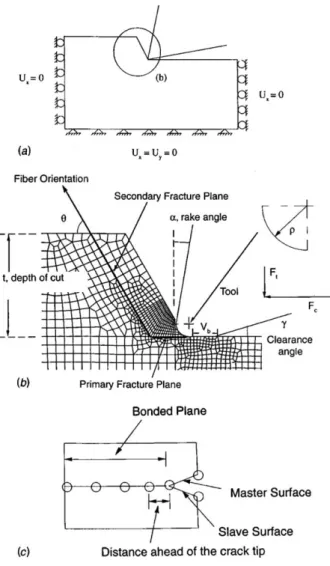
To facilitate the explanation of the cutting mechanisms, [Arola and Ramulu, 1997] defines two rupture paths presented in Fig. 1.1.3. A primary break occurs at the tip of the tool along the direction of the cutting speed. The stress distribution on the primary rupture zone is composed of compression and shear. A secondary rupture then occurs along the fiber / matrix interface from the primary crack to the free edge. It joins the primary break and the free edge.
Fig. 1.1.2: Angles drawn by McKenzie [Mckenzie, 1960].
Because of the two-dimensional configuration, orthogonal process is easier to model numerically than a three-dimensional (oblique) process. The different models that result from it allows for a better understanding of the phenomena present and give the possibility to simulate the mechanisms of formation of the chip, the induced forces and the surface states generated. In orthogonal cutting, all forces, motions, and deformations are in the plane formed by the cutting velocity vector and the direction normal to it [Ahmad, 2009]. To relate the forces encountered during cutting with the identified mechanisms, [Wang et al, 1995] defines them in a fiber-related reference frame where Fs is the component of the cutting forces in the direction of the fibers and Ns is the component of orthogonal cutting forces perpendicular to the fibers (Equ. 1.1.1 and 1.1.2). X2 denotes the angle between the fiber orientation and the cutting plane.
1.1.1 1.1.2
1.1.2. Findings on Cutting Parameters and Generated Defects
1.1.2.1. Cutting Operation and Variables
Chip Formation
Understanding the chip formation mechanism of composite materials is remained a vital part in research. There are some remarkable differences of mechanics of chip formation between metallic materials and composite materials whereas the case of composite materials remained left behind. The chip formation process of composite materials is affected by many process parameters. [Koplev et al., 1983] and [Blanchet, 2015] mentioned that chip formation process in machining FRPs is critically controlled by the fiber orientation and the cutting edge rake angle. [Alaiji et al., 2015] supported the theory of Koplev and added that it is a series of fractures observed in the fibers. Similar observations were later made by several authors [Rao et al., 2008] [Zitoune et al. 2005] [Blanchet, 2015]. There are four basic modes of failure that occur in a composite structure which are matrix cracking, fiber-matrix shearing, fiber failure, and delamination [Ilyas, 2010]. The damage of different components like fiber, matrix, and fiber matrix interface, simultaneously progresses until the complete chip formation process [Blanchet, 2015].
According to [Liu et al., 2012], bending-induced fracture occurs ahead of the cutting edge and perpendicular to the fiber direction. A small distinct chip segment is thus formed and the process repeats itself again. [Pramanik et al., 2007] said, numerically chip separation occurs when the strain value of the leading node is greater than or equal to a limiting value, noting that during the process of chip formation some reinforcements in the cutting region will go into the chip, some will be debonded or fractured and the rest will be on the machined surface. But contrary to the previous findings [Lasri et al., 2009] noted one recent finding that chip formation strongly depends on the microstructure in regard to the local damage caused by the tool cutting edge. They explained the whole process saying fiber–matrix deboning is the first failure developed in composite structure during the cutting process. It initiates near the cutting tool edge and is accompanied with the matrix cracking at different stage of chip formation progression whereas the fiber breaking is the last failure mode occurs in the chip formation process. [Arola et al., 2002] did post-process visual observations of macrochips during the edge trimming process and found that unlike metals, material removal in the machining of FRPs consists of a series of brittle fractures, each resulting in a discrete chip. The process is comprised of ‘‘primary fracture’’, consisting predominantly of fiber failure, and ‘‘secondary fracture,’’ that occurs through matrix failure which is clearly agree with [Alaiji et al., 2015].
At the same time they made a table of the required displacement of tool to form chip with different fiber orientation which has been shown on the Table 1.1.1.
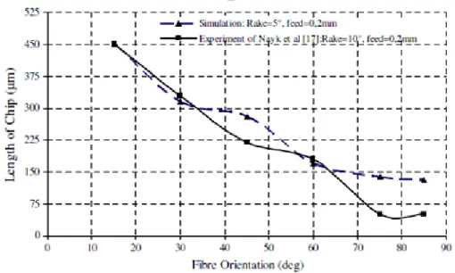
One interesting finding by [Lasri et al., 2009] is that they compared the chip thickness with fiber orientation and then compared the results with the experimental measurements with [Nayak et al. 2005], (Fig. 1.1.4). The chip thickness decreases with increasing the fiber orientation which means there is a strong correlation between the chip formation process and the fiber orientation.
This research was carried out with 5° rake angle and 0.2 mm/s feed rate. The Experimental results of [Nayak et al. 2005] were almost similar indeed a little difference towards 70° to 85° fiber orientation. Regardless of the fiber angle or tool angle there are four different types of chips that have been mentioned in the literatures namely continuous chip, discontinuous chip, continuous chip with build-up edge and serrated chips.
Table 1.1.1: Tool displacement required for chip formation [Arola et al., 2002].
Fig. 1.1.4: Chip thickness with respect to the fiber orientation and comparison with the measured values which obtained by [Nayak et al. 2005].
Cutting and Thrust Force
In orthogonal cutting, the total force F is conveniently resolved into two components, the horizontal direction and the vertical direction. The cutting force takes place in the direction of primary motion (motion of the tool) and the thrust force takes place in the direction of feed motion (vertical). The forces have been shown in the Fig. 1.1.5.
In case of polymers and composites cutting, elastic deformation plays a significant role in determining the cutting force, especially in the tertiary deformation zone. A high degree of fluctuation in the cutting forces is exhibited when machining FRP. Several analytical models [Zhang et al., 2001] [Jahromi and Bahr, 2010] [Bhatnagar et al., 1995] have been found for predicting the forces. [Blanchet, 2015] analyzed the resultant force of Fc and Ft along the fiber direction with respect to the fiber orientations.
There are many parameters which affect these forces. [Wang and Zhang, 2003] and [Alaiji et al., 2015] both mentioned that the machining forces are strongly dependent on the angle X2, which influences the component of the normal force but Alaiji added it is less influenced by the rake angle. The edge acute radius plays an important role on the efforts observed insofar as it is responsible for the elastic spring back, which, according to [Caprino et al., 1998] and [Caprino and Santo, 1998], generates a non-negligible effort with respect to the cutting and thrust forces. The fluctuation of cutting and thrust forces according to fiber orientation has been shown in Fig. 1.1.6.
Fig. 1.1.7: Cutting force history resulting from trimming of unidirectional Gr/Ep with a 10° α / 17° γ cutting tool (a) 60° unidirectional Gr/Ep (b) 90° unidirectional Gr/Ep [Arola et al., 2002]. Fig. 1.1.6: Variation of machining forces with respect to the fiber orientation (a) cutting force, (b) thrust
In Fig. 1.1.6, it is clear that the cutting force increases with increasing the fiber orientation both numerically and experimentally whereas the thrust force increases up to around 450 and then decreases ([Calzada et al. 2012] found the forces are highest at X2= 45° and [S. Zenia et al. 2015] found at 90°). But [Arola et al., 2002] found,in Figs. 1.1.7. and 1.1.8, the cutting force does not increase remarkably until 600 fiber orientation which is not akin with the previous authors. On the other hand, the thrust force remains almost the same until 600 fiber angle and decreases subsequently. [Wang and Zhang, 2003] performs orthogonal cutting tests where he varies the angle of cut from -200 to +400 and the angle X2 from 0° to 150° with 30° increment. Fig. 1.1.9, illustrates the collinear forces at different rake angles; (Fig a) cutting force and (Fig 1.1.9-b) thrust force.
Fig. 1.1.8: Verification of the numerical model with experimental results for orthogonal cutting of Gr/Ep (α=10°, γ=17° (a) principal cutting force (b) thrust force [Arola et al., 2002].
A strong increase in cutting force is observed between 90° and 150°. For a cutting angle greater than 20° the diving force becomes negative from 120° which means that the tool pulls the chip towards outside of the specimen. On the other hand, [Lasri et al., 2009] and [Ghidossi et al., 2003] are not agree totally with Alaiji and Arola. They said that the minimum cutting force occurs in the fiber orientation at 30° for the three criteria and they continued that the thrust force strongly depends on the bouncing back (spring back) phenomenon. Due to this phenomenon, the real and nominal depths of cut are very different. This situation happens when a part of the material in the cutting direction is pushed down during cutting but elastic spring back (partially) happens after the tool passed away. Consequently, the spring back contributes to the generation of the cutting forces [Caprino et al., 1998]. The direct dependence of principal cutting force on the spring back is not important. However, this effect strongly influences the experienced thrust force.
Different angles of cutting tool position play role to the cutting force. [Arola et al., (2002)] mentioned some values of the angles for some definite parameters:
The best tool geometry for minimizing cutting forces has been found to consist of a 15° rake angle.
To minimize subsurface damage, a 10° rake angle tool was found to be optimum.
The minimum stress in the tool nose has been achieved with a 5° rake angle.
The minimum cutting force occurred in the trimming of 30° unidirectional materials. Fig. 1.1.9: Cutting forces as a function of X2: (a) Cutting force (b) Thrust force [Wang and Zhang, 2003].
Th ru st fo rc e ( N ) C u tti n g fo rc e ( N ) (a) (b)
The largest deviation between the numerical cutting force and experimental values occurred in simulations for edge trimming at 0° fiber orientation.
Cutting Tool
Cutting tool plays an important role in all metal cutting processes. Proper materials for tool and an optimum tool design should not only provide a high surface quality, but also minimize tool wear. (Abrão et al., 2008] and [Iliescu et al., 2010] reported that the material of the tool plays an important role in its life duration, such as extending tool life and delamination reduction. Most common materials for tools are: high speed steel, cemented carbide and diamond coated carbides. [Lazar and Xirouchakis, 2011] used solid carbide steels with small grain size (micro-grain) while [Arola et al., 2002] emphasized on Polycrystalline diamond (PCD) and Tungsten Carbide (WC).
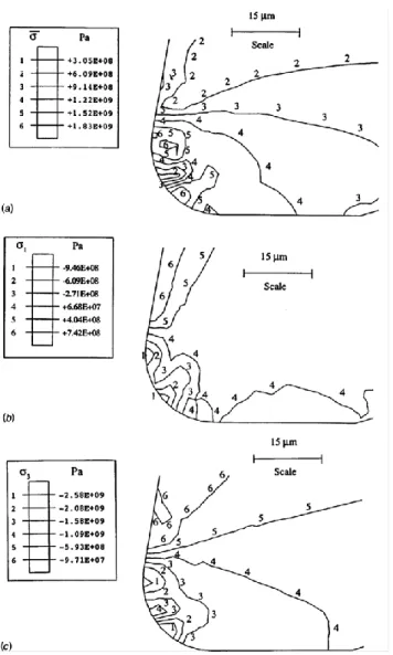
Regarding the tool rake angle [Arola et al., 2002] mentioned that the tool rake angle has limited influence on cutting forces for all orientations other than α=50° and 90°. But the tool geometry does affect the degree of subsurface damage resulting from interlaminar shear failure as well as the cutting tool stress distribution. In the same literature, the stress distribution on the cutting tool is shown which gives a comprehensive understanding of stress intensified areas as in Fig. 1.1.10.
In figure (Fig. 1.1.10) it is clear that the location of maximum principal stress is always found to be near the tool rake face region (Fig. 1.1.10-a). The maximum effective stress is identified in the region as in (Fig. 1.1.10-b) and the maximum normal compressive stress is found to occur in the region (Fig. 1.1.10-c).
Cutting Speed
In orthogonal cutting a diverse range of cutting speed has been tested in research. [Abena et al., 2017] used 0.5 m/min in his numerical and experimental work. [Blanchet, 2015] used 0.5 m/min to 120 m/min to analyzed the surface quality of machined surface. [Klinkova et al. 2011]
Fig. 1.1.10: The stress distribution at the nose of a α = 17° cutting tool resulting from trimming 75° unidirectional Gr/Ep. (a) effective stress distribution (b) maximum principal stress distribution (c)
reported a range of speed mentioning that usually 10 m/min to 40 m/min speed is applied during machining of CFRP. The influence of cutting speed to other parameters have been studied by [Soussia, 2014] and [Iliescu, 2008], (Fig. 1.1.11).
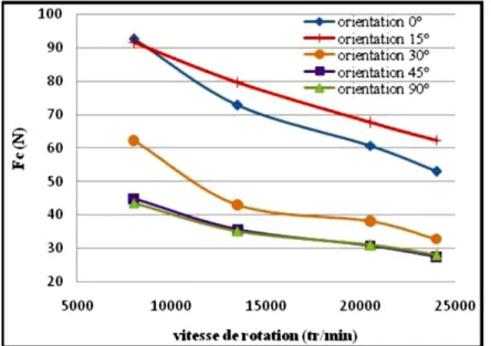
Soussia observed that for the values of X2 between 0° and 90°, the cutting speed tends to increase the thrust force and reduce the cutting force. The values concern cutting speeds between Vc = 12 m/min to 100 m/min. However, since these variations are relatively small and the objective of their work is not to study the effect of speed, it would be reasonable to ignore these effects. On the other hand, from a trimming arrangement [Turki et al. 2011] analyzed the cutting forces as a function of cutting speed (Fig. 1.1.12).
Fig. 1.1.11: Influence of cutting speed on (a) cutting force, (b) thrust forces [Soussia, 2014].
They found that an increase in the cutting speed tends to reduce the cutting forces. So it can be noted that the cutting speed has a significant influence on the forces.
Depth of Cut
Cutting depth is an important parameter in machining. Many researchers mentioned its importance but any specific quantitative proposition regarding the cutting depth has not been found. [Blanchet, 2015] used 0.1 mm cutting depth in his experimentation. [Nayak et al. 2005] used 0.2 mm in his model to compare the chip thickness with respect to the fiber orientation, whereas [Zitoune et al. 2005] varied the depth of cut during orthogonal cutting considering 0.05 mm as representative cutting depth for drilling. They observe that the depth of cut affects the morphology of the chip and further added that for a depth of cut ap = 0.07 mm, a continuous chip is formed and the chip is ejected at the end of the pass; for ap = 0.125 mm, a very friable chip is formed which breaks before the end of cut; and for ap > 2 mm, no chip is observed but fine particles are projected. In orthogonal cutting of CFRP it is not possible to conclude any unique cutting depth for the best quality as other parameters, eg: fiber orientation, cutting speed etc., play important role too. However, cutting depth influence is still a subject of interest for future research.
Feed Rate (associate with drilling)
Feed rate is seen to make the largest contribution to delamination, thrust force and tool wear during machining of composite laminate. According to [Rahman et al., 1999] feed rate combined with depth of cut and cutting speed influence to the fluctuation of tool wear, the surface finish and the cutting force. Generally, the use of low feed rate and high cutting speed favor minimum reduction of the machining-induced delamination, more specially interface delamination [Xu et al., 2016], and extend tool life [Liu et al., 2012]. At low feed rates, the load concentration seems to occur on the chisel edge [Lazar and Xirouchakis, 2011]. However, as the feed rate increases, the loads on the first part of the cutting lip increase more rapidly, becoming the critical area. It should be noted that feed is referred to drilling and it is not a parameter of orthogonal cutting. However, the greater study of machining induced defects draws the drilling parameters into discussion.
Rake and Clearance Angle
In orthogonal cutting the rake angle refers to the rake surface inclined angle from the vertical line and the clearance angle refers to the angle between the bottom surface of the tool and the generated surface of the workpiece. Rake angle determines the direction that the chip follows and the clearance angle provides a small clearance between tool flank and newly generated work surface [Khuzdar, 2013]. A positive rake angle will tend to propagate a crack along the fiber/matrix interface upstream of the tool, while a negative cutting angle will tend to make the
chip flame as said by [Wang et al., 1995] and [Arola et al., 1996]. Cutting parallel to the fibers with a high positive rake angle produces chips by delamination and brittle fracture (peel fracture) but in this condition the continuous chip is form; the transition to smaller positive rake angles favors the formation of discontinuous chips while cutting with zero and negative rake tools produce chips by buckling of fibers perpendicular to fiber orientation by compression. A wide range of qualitative findings regarding these two angles have been found. A few particular rake angles0°, 5°, 10° and 15°with clearance angles 7° and 17° were used by [Arola et al., 2000] for a factorial analysis. They have found that an increasing rake angle decreases the effective cross sectional area of the tool and results in higher contact stress due to a reduction in contact area. An increase in rake angle also causes a decrease in the cutting force. A 5° rake angle has been suggested by them to minimize the tool wear.
Fiber Orientation
In orthogonal cutting of fiber composite laminates, the angle X2 between the cutting direction and the direction of the fibers is an additional parameter which can be referred to the orientation of fibers. Different work from the literature focused on the influence of this angle on cut in terms of phenomenology, surface damage and stresses generated during cutting. Elementary cutting tests were conducted with remarkable values of angle X2; the latter being constant during an orthogonal cutting test. Most authors considered the angles for X2 are 0°, 45°, 90° and 135° (-45°). The first orthogonal sectional CFRP study dates back to [Koplev et al., 1983] which carried out orthogonal cutting tests for an angle X2 = 0°. The CFRP cutting mechanism consists in a series of shavings that create chips. These chips are rarely continuous. In order to observe their shape, Koplev places a thin layer of rubber-based adhesive on the original surface, which allows the chips to be bonded together to form a macro chip. Fiber orientations play an important role on the degree of plastic deformation of the matrix [Pramanik et al., 2007] and may influence friction at the tool / CFRP interface [Klinkova et al. 2011].
[Arola et al., 1996] and [Wang et al., 1995] explained that the cutting angle affects the cutting mechanisms when θ (X2) = 0° (Fig. 1.1.13). If the cutting angle is negative, the chip will be formed by buckling; if it is positive the chip will be formed by bending and crack propagation along the fiber-matrix interface. With the displacement of the tool this crack propagates. The chip is then subjected to a bending load. Wang also performs abruptly interrupted tests with X2 = 45°. The author observes that in the area in contact with the edge, the fibers are crushed in compression by the tool. In addition, the flow plane of the oriented chip along the matrix fiber interface is observed. This surface is highly grooved, which, according to the author, is characteristic of a fragile fracture.
In the case where θ (X2) = 45° (Fig. 1.1.13) the chip is formed by shearing in the fiber-matrix interface, fiber breakage is consecutive and this angle gives rough surface together with crack propagation along the fiber-matrix interface. At the angle X2 = 45° [Zitoune et al. 2005] varies the depth of cut and found that it affects the morphology of the chip. Note that the tool displacement, required for chip formation in the numerical simulations, increases with increasing fiber orientation. Changes in the tool rake or clearance angles do not influence the required displacement [Arola et al., 2002]. Differently, [Koplev and Bunsell, 1980] observed the fracture of laminates and the surface generated at X2=90° and concluded that the tool presses the CFRP until a crack appears along the fiber / matrix interface and creates a chip. At the same time, cracks propagate obliquely to a depth of 0.1 to 0.3 mm. The surface quality is poor compared to that obtained for X2 = 0°. But according to [Wang et al., 1995], at X2 = 90°, fractures occur at the fiber / matrix interface by shear in the plane but also out of plane. The fibers are then sheared perpendicularly to their direction. Fig. 1.1.14, shows the plate of the orthogonal cutting of a test piece with X2 = 90°. Macro-cracks generated by machining are easily observed.
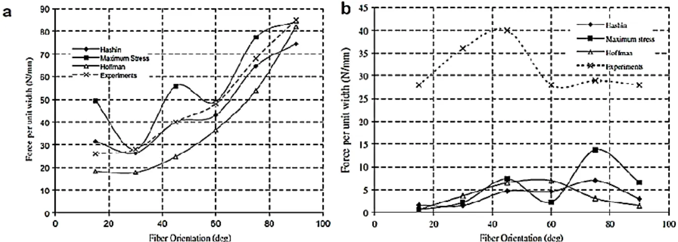
The cracks along the fiber / matrix interface are longer at X2 = 135° than X2 = 90° (Fig. 1.1.14). The process is more difficult to observe in this configuration since the specimen is quickly destroyed by the planning operation [Zitoune et al. 2005]. Cracks are easily observed along the fiber / matrix interface. In the same way as for X2 = 90°, very little literature study the influence of the cutting angle on the cutting mechanisms in the case where X2 = 135°. Some findings about the influence of fiber orientation to subsurface damage have been shown in Fig. 1.1.15 & 1.1.16 [Alaiji et al., 2015] [Lasri et al., 2009].
Fig. 1.1.15: Variation of sub-surface damage with respect to the fiber orientation (a) damage in matrix, (b) fiber-matrix debonding; comparison between values calculated with different criteria: Hashin,
Maximum Stress and Hoffman [Lasri et al., 2009]. Fig. 1.1.14: Cutting mechanisms for X2 = 90° [Zitoune et al. 2005].
Fig. 1.1.15 shows a comparison of subsurface damage with different models, e.g.: Hashin, Maximum stress and Hoffman whereas Fig. 1.1.16 shows the results by Hashin failure criterion. It is clearly visible in both of the Fig. 1.1.15 & 1.1.16 that the subsurface damage increases with increasing the fiber orientation. It seems that the Hashin’s model gives high surface damage values than other two models. According to the Fig. 1.1.15 and 1.1.16 it is possible to come to some points that:
Whatever the model is, the subsurface damage increases if the degree of fiber orientation increases.
The results which are found by different authors are not the same even though the models’ criteria are same. On the other hand, different models give dissimilar results. The cutting forces vary with fiber orientation. [Lasri et al., 2009] compared the cutting force result with fiber orientation using different failure models, Fig. 1.1.17.
Fig. 1.1.16: Variation of subsurface damage with respect to the fiber orientation. Dint and dm indicate damage in matrix and damage in interface, respectively. The cutting conditions are α=10°, γ=6°,
The principal cutting force increases with increasing the fiber orientation for all of the models (Fig. 1.1.17 (a)) and it seems that the experimental values confirm the numerical values of the models. The thrust force and its evolution is low compare to principal cutting force but the experimental values do not support the numerical values (the experimental values were extracted from [Bhatnagar et al. 1995]).
Multidirectional Laminates Cutting
[Arola et al., 1996] carried out tests on stratified specimens having layer of 0°, 90°, 45°, and 135°. They explain that during cutting these types of laminates, each ply behaves independently. However, the off-plane bending generally present for orientations X2 > 90° is suppressed by the adjacent plies. The (Fig. 1.1.18) from [Iliescu, 2008] shows visually the machined surfaces of multidirectional specimens.
Fig. 1.1.17: Evolution of cutting forces with respect to the fiber orientation θ (X2) (comparison between experimental and simulated values), (a) principal cutting force (b) thrust cutting force. The experimental
There is clear difference on the surfaces among the different folds having distinct fiber orientation values. It also appears that the surface state of the folds at 135° fiber orientation is improved with respect to the surface condition of an unidirectional specimen at X2 = 135° machined under the same conditions (Fig. 1.1.19).
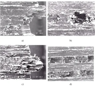
Fig. 1.1.18: Damage of multi-directional specimen with H13A tool for Vc = 60 m/min, f = 0.2 mm: a) interface 45°/90°/135° for γ= 15°; b) interface 0°/135°/0° for γ = 15°; c) interface 0°/45°/0° for γ = 15°; d)
interface 0°/135°/0°/135° for γ=30° [Iliescu, 2008].
It is thus observed that the folds at X2 = 135° have a behavior during cutting which is influenced by the adjacent plies.
1.1.2.2. Machining Induced Defects
Crack Generation and Propagation
A strong influence of fiber orientation to the direction of crack generation and propagation in composite laminates has been found by [Blanchet, 2015], indeed cutting tool angle also plays role behind it. [Pramanik et al., 2007] reported that cracks are generated due to debonding of particles (case of glass-fiber and matrix debonding) in front of tool whereas [Shchurova et al., 2016] said the main reason for this fact is the high strength of fibers in comparison with the matrix one. These are the general reasons. To understand this physics in details, it can be reasoning to focus more on the damage mechanism of composite laminates. According to [Lasri et al., 2009], damage mechanisms in composite laminates include four types of failure modes: transverse matrix cracking, fiber– matrix interface debonding, fiber rupture and inter-ply delamination. They carried out simulations with different stress criteria and found that in cases of Hashin and Maximum stress criteria (Fig. 1.1.20-a and 1.1.20-b), fiber–matrix interface debonding is the first damage developed in the composite structure during the chip formation process. Matrix failure starts and progress in the same way as fiber–matrix interface failure before complete debonding, then continue to propagate in depth until completion of the chip formation. But in case of Maximum stress criterion, (Fig. 1.1.20-b), matrix failure initiates late and then gradually progresses in the vicinity of the cutting tool edge. The fiber breaking is the last failure occurring during the chip formation process in both Hashin and Maximum stress criteria.
According to these findings it can be said that transverse failure can occur without breaking the longitudinal fibers. Such failures, occurring parallel to the fibers may take place during machining and leads to the stiffness degradation.
Delamination
Delamination is an inter-ply failure phenomenon which is a highly undesirable problem and has been recognized as a major damage encountered when machining composite laminates [Liu et al., 2012]. In laminated materials, repeated cyclic stresses, impact, and so on can cause layers
to separate, forming a mica-like structure of separate layers, with significant loss of mechanical toughness which can lead to failure in use [Lazar and Xirouchakis, 2011]. [Lachaud et al., 2001] and [Piquet et al., 2000] discussed delamination in terms of drilling and found that the major delamination is generated during the entrance and exit of the tool into the workpiece which can be the same case for orthogonal cutting. The initial delamination is propagated with the advance of the tool [Rahme, 2008]. Delamination is not usually visually detectable and a special inspection process is necessary. There are some instruments which can be used to observe the delamination which are: optical microscope, stereomicroscope, ultrasonic C-scan, digital photography technique, shadow moiré laser based imaging technique and X-ray computerized tomography (CT).
It was reported that, in aircraft industry, the rejection of parts consist of composite laminates due to drilling- induced delamination damages during final assembly was as high as 60% [Liu et al., 2012]. Throughout the literature study there are many theoretical suggestions found on how to reduce the delamination indeed the experimental validations were limited. High speed cutting is one of the promising technologies for reducing delamination which is mentioned by [Gaitonde et al. 2008] and they further explained that the delamination tendency decrease with increase in cutting speed and the combination of low feed rate and point angle are also essential in minimizing delamination during high speed cutting of composite laminates. It is believed that there is a critical thrust force below which no delamination appears [Hocheng and Tsao, 2005] and to avoid this delamination the thrust force applied to work-piece should not exceed the critical thrust force [Liu et al., 2012].
Spring Back
The edge radius of cutting tool plays an important role on the spring back phenomenon. Spring back generates a significant proportion of the diving effort which is supported by [Arola et al., 2002] and they added that it contributes to the thrust force component of cutting. An extended explanation for this phenomenon has been given by [Wang and Zhang, 2003] which explains that when the tool cuts the material, a part of the cut material is elastically deformed when pressed under the tool. When the cutting operation is completed, a bouncing-back of the uncut material is observed. The actual feed depth is thus different (lower) from the nominal pass depth. (Fig. 1.1.21) illustrates this phenomenon.
[Blanchet, 2015] analyzed the spring back phenomenon with negative and positive rack angle and found that it varies with varying rack angle. An addition by [Wang and Zhang, 2003] is that in the case where X2 < 90°, the elastic spring back is equal to or slightly greater than the radius of acuity. In the case where X2 > 90°, the elastic spring back can go up to 2 times the radius of acuity.
Surface Damage
The surface condition of a machined CFRP part in an orthogonal section is sensitive to a large number of parameters.[Pramanik et al., 2007] found that the newly generated surfaces remain under compressive residual stress and these surfaces are damaged due to cavities left by the pull-out of fibers whereas [Shchurov et al., 2016] said it is the interfacial debonding between fibers and matrix in the area under machined surface which is responsible and the values cohesive bonding strength increases with increased separation, reaches a maximum value before causing permanent debonding [Nayak et al. 2004] . According to [Wang and Zhang, 2003], [Koplev, 1983] and [Iliescu, 2008] , the larger the cutting angle the higher the roughness. Wang indicate that the sub-surface damage is linked to the orientation of the fibers, the feed depth and to the cutting angle. Fig. 1.1.22-a shows the surface condition following an orthogonal cut-out for X2 = 0° in which [Koplev et al., 1983] said the surface state is "relatively good", the cracks do not exceed a depth of 2 times the diameter of the fibers. In Fig. 1.1.22-b the surface condition for X2 = 90° is of "poor quality". Sub-surface cracks with a depth from 0.1 mm to 0.3 mm are observed inside the composite (more than fifteen times the diameter of the fibers).
(a) (b)
Fig. 1.1.23 shows the roughness induced using four different rake angles with different fiber orientations where the roughness increases only after 90° fiber orientation (the other criterions of roughness are not indicated)[Wang and Zhang, 2003].Wang further noted that the extent of this damage varies as a function of the cutting angle.
The best surface condition according to [Zitoune et al. 2005] is obtained for X2 = 45° indeed [Arola et al., 2002] [El Alaiji et al., 2015] found at 90° trimming at 0° rake angle and [Lasri, 2009] found at 30° fiber orientation. The worst being obtained at X2= 135° by Zitoune whereas Lasri
Fig. 1.1.22: (a) Surface condition following an orthogonal section planning for X2 = 0°. (b) X2 = 90° [Koplev et al., 1983].
Fig. 1.1.23: Roughness versus X2 for multiple cutting angles. The depth of cut is 0.05 mm [Wang and Zhang, 2003]
said the worse starts beyond 45° fiber angle. Zitoune clarified that when X2 = 45°, the fibers and the matrix are sheared cleanly with good surface condition. At the contact between the test piece and the tool, the plane of sliding of the chip is observed (Fig. 1.1.24-a and 1.1.24-b). The author also explains that at X2 = 0°, bending induced chip breaking leaves fibers raised. This phenomenon is illustrated by photographs Fig. 1.1.24-c and 1.1.24-d.
The subsurface damage varies with different failure models. [Lasri et al., 2009] carried out research with three different models and saw that in case of Hashin criterion, the sub-surface damage in the matrix and the extent fiber–matrix debonding are close each other, while in the case of Maximum stress criterion, the predicted sub-surface damage in the matrix below the flank plane is lower than the extent of fiber–matrix debonding and localized around the cutting tool edge. However, the Maximum stress criterion predicts fiber–matrix debonding deeper than what predicts Hashin criterion. [Arola et al., 1996] found that the extent of damage to plies can be limited if the surrounding plies are oriented in different direction. For all fiber orientations, the subsurface damage, such as matrix cracking, fiber–matrix debonding and predicted Hoffman damage starts near the cutting tool edge and propagates in directions parallel and perpendicular to the fiber inside the workpiece [Lasri, 2009].
Fig. 1.1.24: Enlargements of a machined surface with cutting depth ap = 0.25 mm: (a) X2 = 45°; (b) enlargement of (a); (c) X2 = 0°; (d) enlargement of (c) [Zitoune, 2004].
To reduce surface damage [Shchurov et al., 2016] said one of the ways to reduce such damage is special deformation redistribution, such that fibers have to be lesser stretched after the cutting wedge indeed [Arola et al., 2002] emphasized on tool angle, saying a tool with 10° rake angle would minimize damage.
Tool Wear
Abrasive wear, chipping, and adhesion are attributed to the tool wear mechanisms during machining of composite laminates. Although existing models can provide estimates for the principal cutting forces resulting from orthogonal cutting, tool wear is often overlooked [Arola et al., 2002]. A lot of research work identified abrasive wear as dominant tool wear mechanisms in composite laminates cutting due to the highly abrasive nature of the carbon and glass fibers [Liu et al., 2012].Abrasive wear mechanism is a mechanical wear that is caused by scratching action of hard fibers inside the soft polymer matrix [Pramanik et al., 2007].
The Fig. 1.1.25 shows the flank wear during drilling which can be taken into consideration to analyze orthogonal cutting. On the figure the numbers are the references mentioned at [Liu et al., 2012]. It can be seen that the flank wear increases with increasing the cutting speed but in case of feed rate it remains controversial among different authors. In order to reduce the tool wear Liu said that carbide tools, coated carbide tools and PCD tools yield good results in terms of tool wear and tool life.
1.1.3. Various Developed Models in CFRP Machining
Different kinds of models have been developed by researchers depending on their objectives. Here, a few Micro, Macro and Analytical models have been presented.
1.1.3.1. Micro-mechanic Models
Model of [Abena et al., 2017]
Abena has proposed a new approach for the cohesive interface. The model employs zero thickness of the cohesive elements following the traction-separation law. The simulations have been carried out with 0°, 45°, 90° and 135° fiber orientation. The authors emphasize that the model can represent very thin interface behavior. It showed good agreement regarding the cutting and thrust forces with respect to different fiber orientations against the published literature findings. Fig. 1.1.26, shows the traction separation law for the cohesive model.
The linear elastic response in this model is composed by normal and shear behavior. The strains ԑ are displaced by δ by means of the Eq. 1.1.3.
1.1.3
Here the T0 represents the constitutive thickness and the n, s, and t indicate the normal and the two shear directions respectively. The linear elastic behavior until the damage is initiated according to the Eq. 1.1.4.
1.1.4
Here, t̅, p̿, and ԑ̅ represent the stress vector, the stiffness matrix and the strain vector respectively. Once the stress and displace reach point 2 (Fig. 1.1.26) the interface reaches its Fig. 1.1.26: Cohesive model based on traction–separation law and mechanical response for (left) normal
yield point and crossing this point initiates the damage. The damage initiation in this model has been chosen based on quadratic nominal stress criterion, coupling traction and shear behavior as Eq. 1.1.5.
1.1.5
Here the Macaulay brackets ‹› mean that no damage initiation is possible under compressive behavior. The degradation of adhesive phase has been expressed in Eq. 1.1.6.
1.1.6 Here
1.1.7 In the Eq. 1.1.6, dn/s/t represents the damage variable introduced for each failure mode, δ0n/s/t δtn/s/t, δmaxn/s/t represent the displacement at the damage initiation, the displacement at failure and the maximum displacement reached during the analysis until the time considered respectively. They found that for 0° fiber orientation the cohesive element’s shear and tensile stress both together are responsible for damage initiation and evolutions until failure with bigger contribute of the shear for damage initiation. On the other hand, for 45°, 90° and 135° fiber orientation the shear stress is mainly responsible for damage initiation and failure.
Model of [Alaiji et al., 2015]
The authors have developed a three-dimensional (3D) finite element (FE) model to study the machining of unidirectional (UD) carbon fiber reinforced polymer composite (CFRP). The objectives of this study were to analyze the physical mechanisms responsible in the chip formation process, to predict the cutting forces and to simulate the cutting induced damage.
![Fig. 1.1.7: Cutting force history resulting from trimming of unidirectional Gr/Ep with a 10° α / 17° γ cutting tool (a) 60° unidirectional Gr/Ep (b) 90° unidirectional Gr/Ep [Arola et al., 2002]](https://thumb-eu.123doks.com/thumbv2/123doknet/2132844.8637/30.918.165.748.112.384/cutting-history-resulting-trimming-unidirectional-cutting-unidirectional-unidirectional.webp)
![Fig. 1.1.8: Verification of the numerical model with experimental results for orthogonal cutting of Gr/Ep (α=10°, γ=17° (a) principal cutting force (b) thrust force [Arola et al., 2002]](https://thumb-eu.123doks.com/thumbv2/123doknet/2132844.8637/31.918.300.621.149.658/verification-numerical-experimental-results-orthogonal-cutting-principal-cutting.webp)
![Fig. 1.1.13: Formation of chip with respect to different fiber orientations [Wang et al., 1995]](https://thumb-eu.123doks.com/thumbv2/123doknet/2132844.8637/38.918.264.639.108.562/fig-formation-chip-respect-different-fiber-orientations-wang.webp)
![Fig. 1.1.28: Schematic view of orthogonal cutting model showing the tool geometry, composite workpiece and boundary conditions [Lasri et al., 2009]](https://thumb-eu.123doks.com/thumbv2/123doknet/2132844.8637/53.918.113.799.106.406/schematic-orthogonal-cutting-geometry-composite-workpiece-boundary-conditions.webp)