Science Arts & Métiers (SAM)
is an open access repository that collects the work of Arts et Métiers Institute of
Technology researchers and makes it freely available over the web where possible.
This is an author-deposited version published in: https://sam.ensam.eu
Handle ID: .http://hdl.handle.net/10985/19663
To cite this version :
Roberto M. SOUZA, Michell F.C. ORDOÑEZ, Sabeur MEZGHANI, Samuel CREQUY, Newton K.
FUKUMASU, Izabel F. MACHADO, Mohamed EL MANSORI - Orthogonal cut of SPS-sintered
composites with ferrous matrix and Fe Mo S particles: Numerical and experimental analysis
-Tribology International - Vol. 149, p.105750 - 2019
Orthogonal cut of SPS-sintered composites with ferrous matrix and
FeeMoeS particles: Numerical and experimental analysis
Roberto M. Souza
a,b,∗, Michell F.C. Ordoñez
a, Sabeur Mezghani
b, Samuel Crequy
b,
Newton K. Fukumasu
a, Izabel F. Machado
a, Mohamed El Mansori
baLaboratório de Fenômenos de Superfície, Escola Politécnica da Universidade de São Paulo, Brazil
bMechanics, Surfaces and Materials Processing Laboratory (MSMP), Ecole Nationale Supérieure D’Arts et Métiers, France
Keywords:
Metal-matrix composites Solid lubricants Machining
Finite element modeling
A B S T R A C T
Metal-matrix composites with solid lubricant reinforcements may present a suitable alternative to improve the tribological behavior of sintered components. Besides the performance during the application, the presence of solid lubricants may also modify component manufacture, for example, during machining operations to achieve complex shapes not directly obtained from the sintering process. This work describes a numerical and experi-mental analysis on the orthogonal cut of metal-matrix composites composed of FeeMoeS particles embedded in an Astaloy 85 Mo (Höganäes AB) matrix. Specimens were prepared using the Spark-Plasma Sintering (SPS) technique, from mixtures containing powders of Astaloy 85 Mo steel and 2 wt% or 4 wt% of molybdenum dis-ulfide (MoS2). An unreinforced Astaloy 85 Mo specimen (without MoS2) was also included in the analysis.
Different microstructures were observed after SPS. The unreinforced specimen presented a ferrite-pearlite structure with a porosity level below 2% and the specimen sintered with 2 wt% of MoS2presented iron sulfide
particles dispersed in the steel matrix. The structure of the specimen sintered with 4 wt % was more complex, with two distinct phases dispersed in the Astaloy 85 Mo matrix. Experimental orthogonal cuts were conducted on the three specimens using a shaper machine tool equipped with a tungsten carbide (WCeCo) cutting insert. Tests were recorded using a high-speed camera. The machined surfaces were later analyzed with an optical profil-ometer and in a scanning electron microscope (SEM) with energy-dispersive X-ray spectroscopy (EDS). The chips were also characterized. The cutting operation was simulated by two-dimensional (2D) finite-element analysis. The meshes were prepared based on the specimen microstructures and considering the properties of the in-dividual phases. Results have indicated significant differences in the cutting process. Observation of the chip surfaces indicates plastic deformation on the unreinforced specimen, in opposition to more uniform scratches on the composite surfaces, especially that of the specimen sintered with 4 wt % of MoS2.
1. Introduction
In current industrial practice, there is an increasing demand for machining of workpieces of different materials at higher cutting speeds, maintaining high productivity and performance [1,2]. Another trend is the reduction of liquid lubricants commonly used in wet machining, which is desirable from the point of view of decreasing operational cost and reducing environmental damage [3]. However, surface finishing precision and efficiency in dry machining usually impose additional requirements in terms of friction reduction as well as heat dissipation at the cutting tool/chip interface [4,5]. The cutting temperature is de-pendent on the cutting speed as well as on the materials in contact. For higher cutting temperatures, the hardness of some materials decreases
significantly, modifying the geometry of the cutting edge and the workpiece surface finishing quality [6]. More specifically, for dry-ma-chining of soft materials like austenitic stainless steel and aluminum, hardness reduction may difficult the material flow outside the cutting zone, due to adhesion and built-up edge formation, increasing the tool wear [7–9].
Previous works showed that the presence of low-shear materials at the chip/tool interface may improve the cutting by reducing both the friction coefficient and interfacial temperature [10,11]. These mate-rials, frequently formed as tribofilms, originate from the tool material, are transferred from the workpiece, or from the interaction of the ma-terials with the environment [12]. That interaction usually produces compounds that are continuously generated and removed during the
∗Corresponding author. Laboratório de Fenômenos de Superfície, Escola Politécnica da Universidade de São Paulo, Brazil. E-mail address:robertosouza@usp.br(R.M. Souza).
cutting operation. One common way to obtain these tribofilms involves the application of protective coatings onto the tool surface, leading to the presence of low-friction layers. Examples of soft coating used in this category are the solid lubricants, such as molybdenum disulfide (MoS2),
which present low shear resistance due to its lamellar structure [13]. Hard coatings like diamond-like carbon or cubic boron nitride may also increase the tool life and reduce friction and wear, being suitable for dry machining operations [14,15]. Although the choice of these coat-ings offers many advantages, formation of a brittle interface and the high deposition temperature of some processes may be a disadvantage [6]. Another method that involves tool modification is the fabrication of a micro-textured pattern produced by sintering or laser methods, for the formation of anti-adhesive cutting surfaces [16]. The addition of a solid lubricant such as graphite into of the micro-pattern generates a tribofilm on the rake face, which reduces friction [17].
An efficient route towards friction reduction involves sintering of a powder mixture containing the workpiece material and low-friction particles. The fabrication of these self-lubricant composites by ad-vanced methods such as spark plasma sintering (SPS) has expanded its application field, mainly due to the possibility of obtaining composite-like materials with minimal porosity and with a set of tribological features that are not found in conventional materials [18]. The sintering process offers the option of adding different solid lubricants, allowing an improvement in machinability, since tribofilms may be obtained without modification of the tool surface, avoiding or reducing the need of cutting fluids.
Different investigations reported the positive effect of solid lu-bricant addition in diverse sintered materials, for both friction and wear reduction. Addition of graphite and hexagonal boron nitride in iron matrix composites increased the scuffing resistance during dry sliding tests, due to the formation of a self-replenished tribolayer composed of both solid lubricants [19]. For Cu-WS2sintered composites, the bending
strength and the tribological properties depend on the WS2particle size.
For smaller particles, a higher interface area increases oxidation and formation of products that increase friction and wear. Moreover, larger particle sizes produced more resistant composites, due to the formation of a more continuous and protective tribofilm that reduced the wear rate [20]. Self-lubricant composites with steel matrix and MoS2
addi-tion produced a microstructure composed of MoS2and FeS phases that
generated a tribofilm with lower friction and wear, during sliding tests conducted between 150 and 350 °C. However, above 350 °C the pre-sence of MoO3 and Fe3O4 oxides reduced the MoS2 lubrication and
increased the FeS phase superficial migration, which provided lu-brication at this temperature range [21]. In machining operations that were conducted using tools made of Al2O3/TiC ceramic matrix with
additions of up to 10 vol% CaF2,it was reported the formation of a low
friction layer. This tribofilm formed at the tool-chip interface reduced the friction coefficient and protected the ceramic matrix from severe wear by brittle microfracture [10]. Previously mentioned sintering techniques allow to manufacture and obtain metal matrix composites with a range of reinforcement characteristics, such as particle size,
morphology and volume fraction, which are difficult to control with conventional manufacturing methods. In the last years, the application of sintered materials was restricted, due to the presence of high porosity levels, which may reduce the mechanical and tribological properties. Nevertheless, the development of advanced sintering techniques such as SPS may lead to samples with higher densification and may expand its application to new fields in engineering. Therefore, it is important to study the mechanical and tribological properties of these SPS sintered composites and to analyze its behavior, for example during machining. The finite element method (FEM) may be a complementary tool to evaluate the friction forces and the stress distribution at the chip-tool interface for different materials in cutting operations [22,23]. Overall, the material response depends on the contribution of different zones along this interface. The primary shear zone is located from the cutting edge to the work surface. High shear deformation at this zone is re-sponsible for local heating and material softening [4]. The material deformation and sliding along the rake face contributes with tempera-ture rise at the secondary shear zone [5]. The selection of the cutting conditions (i.e cutting speed, feed, depth) influences the temperature and strain distribution at the different zones. For example, FEM ana-lyses of the cutting of pure Ti and Ti6Al4V were useful in predicting the segmented chip formation by adiabatic shear for different cutting speeds [24,25]. In analytical-numerical modeling of machining of ductile AISI 1045 steel with a TiAlN coated tool, sliding and sticking zones were defined at the tool-chip contact for determination of cutting forces, temperature and stress distribution, providing good agreement with experimental results [9].
Few works have used FEM analyses to study machining of materials that present low shear phases [26,27]. One example refers to the FEM simulation of the machining of commercial AISI 303 austenitic stainless steel containing manganese sulfide (MnS) particles. Results have in-dicated that during dry machining the sulfide secondary phase may act as stress concentration points. Thus, secondary phases with more irre-gular morphology or the presence of a higher volume fraction may increase these stress concentration regions and enhance the cutting efficiency [28].
This work investigated the cutting performance of SPS sintered Astaloy85Mo steel with additions of 2 wt% or 4 wt% of molybdenum disulfide (MoS2). Analyses were based on orthogonal cut operations in
different cutting depths. The effect of the solid lubricant on the mi-crostructure, mechanical properties and on the tribofilm formation was also studied. The experimental results were compared with FEM si-mulations for the cutting of these materials in terms of friction forces and self-lubricant behavior.
2. Experimental and numerical procedure
2.1. Workpiece material
Low alloy steel Astaloy 85Mo (Fe-0.85 wt%Mo-0.27 wt% C) was selected as the matrix material. The as-received (commercial) ferrous
Nomenclature
ρa apparent density [g.cm−3] ρr relative density [%] FR relative frequency [%]
vc cutting speed [m/min] γ rake angle [o]
lc cutting length [mm] COF coefficient of friction
Ft, Fr, Fa tangential, radial and axial force components [N] d cutting depth [μm]
Er reduced elastic modulus [GPa]
v Poisson's ratio
H hardness [GPa]
εf equivalent strain to fracture εp equivalent plastic strain σ1 yield stress [MPa]
τmax maximum shear stress [MPa]
Ad, Bd, As, Bs, Cs, k workpiece model constants
Sa arithmetic mean height surface roughness [μm] Sq root mean square height surface roughness [μm] Str surface texture isotropy percentage [%] Sv maximum valley height surface roughness [μm]
powder, with average particle size on the order of 100 μm, was milled with a planetary ball mill (Fritsch Pulverissete 4) using a ball-to-powder weight ratio of 10:1 under argon atmosphere. Each milling procedure was carried out in a total time of 10 h, which corresponds to 60 cycles with 10 min ON and 20 min OFF, to avoid overheating. Different amounts (2 and 4) wt. % of MoS2powder (Jet-Lube, Inc) were added to
the ferrous powder. These materials were homogenized using a Y-type mixer during a period of 4 h. The mixtures were consolidated by spark plasma sintering (SPS) using a DR. SINTER SPS1050 (Sumitomo Coal Mining Co. Ltd, Japan) equipment. The powders were pressed uni-axially into a graphite mold of 20 mm of diameter with a pressure of 70 MPa and simultaneously heated up to a temperature of 1000 °C with a heating rate of 100 °C. min−1. These conditions were held for 5 min.
Overall, three materials were considered in this work: steel with addi-tions of 0 (unreinforced), 2 wt % and 4 wt % of MoS2.
2.2. Tool material and cutting test
Dry cutting tests were conducted using a GSP-EL 136-shaper ma-chine with triangular TCMT16T304 WC-Co inserts mounted on a tool holder. Tests were carried out with the same cutting speed, vc(32 m/
min) and with two cutting depths, d (0.15 and 0.20 mm). Three dif-ferent passes were performed for each condition. During the cutting operation, tangential (Ft), radial (Fr) and axial (Fa) force components
were measured by means of a piezoelectric Kistler dynamometer (type 9255B) (Fig. 1b). A denoising filter was later used to improve the signal-to-noise ratio during the cutting stage and the average force was calculated. To analyze the workpiece response for each condition an in-situ observation was conducted using a high-speed camera with an acquisition rate of 6000 fps. The experimental procedure for material preparation, in conjunction with the cutting test, is summarized in
Fig. 1a.
2.3. Material characterization
The apparent density (ρa) of each sintered material was measured
using the Archimedes principle, according to the ASTMB962-17 stan-dard. The relative density (ρr) was obtained by comparison of the
composite density determined using the rule of mixtures, which in-cludes each phase density (Astaloy 85Mo: 7.85 g cm−3 and MoS
2:
5.06 g cm−3), with the experimental apparent density. For the
me-tallographic preparation, samples were ground with 320-grade SiC paper and polished with diamond suspensions up to 1 μm. Microstructural observation and chemical composition analysis of each material was carried out by means of scanning electron microscopy (SEM - JEOL-JXA8600) with Electron Probe Microanalyzer (EPMA) using different 99.99% purity standards of Fe, C, Mo, and MoS2, for
elemental energy calibration. The crystalline phases in the different samples after sintering were identified by means of X-ray diffraction analysis using an XRD-6000 Shimadzu diffractometer with Cu-Kα ra-diation and Bragg-Brentano (ϴ -2ϴ) geometry. Data was collected using a tube current of 30 mA and a tube voltage of 40 kV, with the angular 2ϴ range from 20° to 100° at a step size of 0.05° and 5s of integration time. XRD patterns were indexed with the aid of the X'Pert High Score Plus Software and the PDF-2 database (The International Centre for Diffraction Data-ICDD).
The bulk hardness of each material was determined using a Buelher 1900–2000 Vickers testing machine under a load of 10 Kgf (98.07 N) and using 10 s of holding time. Individual phase properties of the fer-rous matrix and secondary phases were measured with instrumented indentation (nanoindentation) using a Hysitron TI950 triboindenter equipped with a Berkovich diamond tip, also capable of scanning probe microscopy (SPM) analyses. For Astaloy 85Mo with 2 wt% MoS2, five
measurements were conducted for each phase with a peak load of 2 mN. The hardness and Young's modulus were obtained from load-displace-ment curves, according to the Oliver and Pharr method. After the
cutting tests, the cross-section and the surface of the chips were ana-lyzed using SEM (JEOL-JSM 6010LA) coupled with elemental mapping by energy dispersive X-ray spectrometry (EDS). The effect of the solid lubricant in the roughness and texture was measured with a 3D pro-filometer (Taylor Hobson – CCI HD).
2.4. FEM-finite-element modeling
Two-dimensional (2D) finite element modeling of the orthogonal cut of the metal matrix composites was conducted using the TRIBOCode digital tribology platform developed at the Surface Phenomena Laboratory (LFS-USP) [29,30]. The FEM model considered both homogeneous and heterogeneous microstructures, to evaluate the in-fluence of the sulfides during machining. Although literature reports the importance of temperature on the cutting process [4,5], models in this work considered isothermal room temperature conditions. This restriction allows the observation of the stress concentration features of the heterogeneous material, but does not take into account the decrease in matrix ductility usually promoted by the heating of the material during the cutting process. The tool was considered as rigid, with a tool cutting radius of 30 μm and a rake angle γ of 6°. The total machining length was 3.3 mm, such that only the initial steps of the cutting op-eration were simulated. Only the cutting depth d of 0.20 mm was considered.
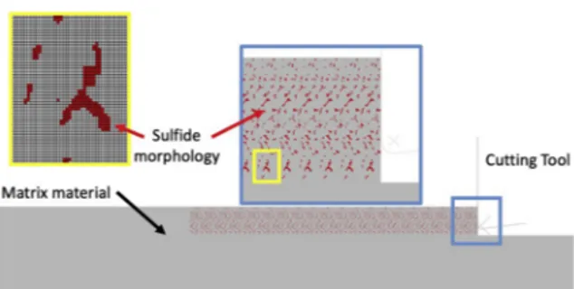
The bulk geometry was discretized by a mesh with spatial resolution of 1 μm, totalizing 1,117,325 quadrilateral plane strain elements of type CPE4R. The heterogeneous material was modeled based on an SEM image of the composite material microstructure, in which mesh ele-ments were selected to represent the morphology of the sulfides.Fig. 2
presents the heterogeneous mesh, in which the total cutting length was 6 mm and total sample thickness 1 mm. Ideal interfaces between matrix and sulfides were considered.
The material failure model for the matrix and the sulfides con-sidered both ductile and shear modes, which are described in the lit-erature for a large range of materials [31–33]. The failure modes allow the element deletion of the mesh, leading to crack nucleation and propagation throughout the material. The nucleation of cracks was based on initiation failure criteria, given by Eq.(1)and Eq.(2). In these equations,q
pis the stress triaxiality,q kpmax+ is the shear stress ratio, f is the fracture strain and A B A Bd, d, s, sand Cs are model constants. Ma-terial parameters, presented inTable 1, were tuned to reproduce the experimental cutting behavior, including similar cutting force magni-tude. Values present physical meaning, but should not be considered as the precise properties of these materials. In the absence of data for Astaloy 85 Mo, the material failure energy, which allows the
Fig. 1. (a) Schematic representation of the samples preparation and cutting test evaluation and
(b) photograph of the cutting setup before the first cutting pass.
propagation of cracks, was defined as 10 J/m2, which is a value for AISI
1045 steel. The models considered time dependent and isothermal room temperature condition for dry machining with a cutting speed (vc)
of 32 m/min. = + q p A lnd ( )f Bd (1) =A q+kp +B q+kp +C f s max s max s 2 (2)
3. Results and discussion
3.1. Powder characterization
In this work, ball milling was selected to reduce the Astaloy 85Mo powder particle size.Fig. 3shows the particle size distribution of as-received Astaloy 85Mo and molybdenum disulfide (MoS2) powders.
Both powders exhibit a monomodal distribution with a significant dif-ference in average particle size, of 100 μm for Astaloy 85Mo and 5 μm for MoS2.
After 10 h of milling, the Astaloy 85Mo powder distribution changed to bimodal (Fig. 3) with a lower average particle size of 24 μm. This reduction is a result of continuous cycles of ball impingement, which cause plastic deformation, work-hardening and fracture.Fig. 4
presents SEM-EDS mapping of the powder of Astaloy 85Mo with 4 wt% MoS2after mixing in a Ye type mixer. This figure indicates a
homo-geneous mixture of well-dispersed MoS2 particles on the surface of
flake-like Astaloy 85Mo particles.
3.2. Workpiece characterization
Table 2summarizes the density and hardness of the sintered sam-ples. The selected choice of SPS parameters provided efficient
densification for the Astaloy 85Mo, with relative density near 100%. Solid lubricant addition slightly reduced the density and increased the hardness, with a more significant effect on hardness for the sample with the addition of 2 wt% of MoS2.
Fig. 5presents backscattered scanning electron (BSEM) micrographs of the sintered Astaloy 85 Mo with solid lubricant addition. The addi-tion of 2 wt % of molybdenum disulfide contributed with the formaaddi-tion of a dark-gray phase with irregular morphology. This morphology may introduce stress concentration points due to local mechanical property differences between the sulfide particles and the surrounding matrix. The sample with 4 wt % MoS2addition exhibits the dark-gray irregular
phase as well as a second lighter phase, which was smaller and with a rounded morphology.
EPMA quantitative analysis helped to determine the elemental composition of each phase, as shown inFig. 6. The dark-gray phase, termed as phase 1, presented Fe (50.84 at. %) and S (46.85 at. %) as major constituents and corresponds to iron sulfide (FeS). In addition, the lighter and round phase, termed phase 2, with contents of Fe (53.64 at. %) and Mo (39.14 at%.), indicate iron molybdenum (Fe3Mo)
formation. Note that the variability in atomic content may increase for phase 2 particles with dimensions below 1 μm, since measurements may include the surrounding matrix. Moreover, Fe, C and Mo contents for the ferrous matrix were 96.44 at. %, 1.51 at. % and 2.03 at. %, re-spectively. Thus, in comparison with the composition of the starting powder, a higher Mo content, of 2.03 at. % (3.48 wt%), was observed near the dark-gray phase boundaries, which possibly indicates the dif-fusion of the molybdenum from the MoS2 into the ferritic-pearlitic
matrix during sintering.
XRD patterns of the sintered samples are shown inFig. 7. Analyses of the matrix phase indicated a body centre cubic structure that cor-responds to ferrite (Fe-α) (PDF-01-087-0722). The addition of 2 wt% MoS2lead to the formation of an additional phase of FeeS
(PDF-01-080-1027) and an indication of the presence of the Fe3Mo phase
(PDF-00-009-0297). Higher (4 wt%) MoS2addition resulted in a higher
pre-sence of FeeS and Fe3Mo phases, as well as an indication of the
pre-sence of FeMo3S4(01-071-1897). The molybdenum content in the
As-taloy85Mo matrix may enable the complete phase transformation of MoS2into FeeS and Fe3Mo phases [34]. For higher 4 wt% MoS2
addi-tion, the presence of an additional phase formation of FeeMoeS is also observed. Previous works on metal-matrix composites with the addition of MoS2powder, and sintering at temperatures above 950 °C, reported
decomposition of MoS2 into FeS and FeeMoeS more stable phases
[21,35].
Fig. 2. Discretization mesh of the cutting geometry. Regions in gray represent the matrix material while red indicates sulfides for the heterogeneous simula-tion. The detail in yellow shows the mesh discretization of the sulfide mor-phology. (For interpretation of the references to color in this figure legend, the reader is referred to the Web version of this article.)
Table 1
Parameters of the material constitutive models.
Parameters Materials
Matrix Sulfides Elastic modulus, E (GPa) 210.0 160.0 Poisson ratio, v (−) 0.3 0.3 Yield Strength, σ1(MPa) 337.0 776.0
Ad(−) −1.55 −0.5 Bd(−) 0.89 0.3 As(−) 14.09 14.09 Bs(−) −48.75 −48.75 Cs(−) 43.63 43.63 k(−) 0.3 0.3
Fig. 3. Particle size distribution of Astaloy85Mo (black) and MoS2(red)
as-received. Astaloy 85Mo (blue) distribution after10 h of milling. (For inter-pretation of the references to color in this figure legend, the reader is referred to the Web version of this article.)
The hardness and reduced Young's modulus of the phases detected in Astaloy 85Mo with the addition of 2 wt% MoS2 were determined by means of instrumented indentation testing. SPM image shows a sample region, indicating measurement positions inside a dark-gray iron sulfide and on the ferrous matrix (Fig. 8). Results revealed higher hardness and lower reduced Young's modulus for the dark-gray sulfide, in comparison with the ferrous matrix. The lower reduced modulus of these sulfides is
related to its lamellar structure, which presents weak bonding between its multiple sheets and provides low shear resistance [36].
3.3. Cutting forces and chip formation
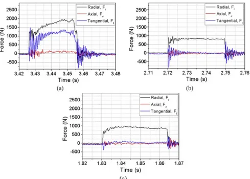
Fig. 9shows the forces (Ft, Fr, Fa) measured during an orthogonal cut with a speed of 32 m/min and depth of 0.15 mm. The low hardness of Astaloy 85Mo without MoS2addition (Fig. 9a) may have increased
the plastic deformation and adhesion on the rake face, which difficult the material flow and increases the radial (Fr) and tangential (Ft) forces with the cutting time and length (lc). Large oscillations at the beginning and at the end of the normal and tangential force signal data for the Astaloy 85Mo steel may be a result of tool vibration as well as the re-sistance of the material to flow. The cutting forces were lower for the composites (Fig. 9b and c), especially the tangential ones, which were negligible in most portions of the cutting time. In this work, friction coefficient can be calculated by the ratio (Ft/Fr) between tangential and radial forces (Fig. 1b), as frequently described in tribological works and considering this particular experiment configuration. However, one must realize that friction coefficient may be calculated differently in publications dedicated to machining operations [37].
Fig. 10compares the average values of radial and tangential forces measured for the sintered materials, for the two cutting depths. For Astaloy 85Mo without MoS2addition, the tangential and radial forces
increased for the highest cutting depth, which may be related to the increment of material removal. Radial force signals were significantly
Fig. 4. SEM-EDS mapping of Astaloy 85Mo with 4 wt% MoS2powder mixture.
Table 2
Density (apparent and relative) and Vickers microhardness for workpiece sin-tered materials.
Material Apparent density ρa(g/cm3) Relative density
ρr(%) Hardness H (HV10) Astaloy 85Mo 7.81 99.5 133.4 ± 2.0 2 wt% MoS2 7.65 98.2 239.2 ± 5.4 4 wt% MoS2 7.56 98.1 198.8 ± 4.2
Fig. 5. BSEM microstructure for Astaloy 85Mo with different MoS2additions
(a) 2 wt% and (b) 4 wt%.
Fig. 6. EPMA quantitative analyses for constitutive phases of the Astaloy 85Mo with 4 wt% MoS2addition.
Fig. 7. X-ray diffractograms of unreinforced Astaloy 85Mo and with MoS2
ad-dition after sintering.
Fig. 8. Determination of Hardness and reduced Young's modulus by means of instrumented nanoindentation coupled with SPM microscope. Astaloy 85Mo with the addition of 2 wt% MoS2.
lower for samples with MoS2addition at both cutting depths.Fig. 10
also confirms the trend observed inFig. 9, in terms of the significantly lower tangential forces observed for the composites. These differences may be explained by the microstructural effect brought by the presence of the sulfide phases.
Fig. 11presents the radial and tangential force values obtained with the simulation of the cutting of the homogeneous (unreinforced) mi-crostructure. In this figure, four values of friction coefficient for the contact between the tool and the workpiece were tested (zero, 0.3, 0.6 and 1.0), and provided a range from 600 to 800 N for the radial force and 50–300 N for the tangential force. The higher COF conditions presented similar cutting forces, suggesting that the effect of the friction coefficient saturates after a value close to 0.6. Although the simulated cutting forces are underestimated in comparison to the experimental values, the numerical procedure allows observing that lower friction coefficient values are capable of reducing both the radial and tangential forces throughout the cutting length (lc).
Chip formation is fundamental to analyze the material response under cutting conditions. The efficiency of chip breaking in dry ma-chining operations influences the superficial quality and tool wear [38]. In-situ high-speed images at different elapsed times were obtained to understand the effect of solid lubricant addition on the efficiency of chip formation (Fig. 12). For Astaloy 85Mo steel, a built-up edge was formed in front of the tool. Higher elapsed times indicate that more material was accumulated (Fig. 12a) at the edge with the movement of the tool. In contrast, the addition of 2 wt% MoS2produces a continuous
curled chip with higher removal efficiency (Fig. 12b andc). The ben-efits of the composite microstructure may be related to an ease in the cutting operation as well as the effect of the solid lubricant in facil-itating shear at the secondary shear zone.
Fig. 13a shows the cross section of a chip of Astaloy 85Mo with MoS2
addition. For the addition of 2 wt% (Fig. 13b), the presence of microcracks in front of the sulfide particles indicates a contribution to the fracture and flow stress at the primary shear zone. High plastic strain through the chip thickness produces highly elongated ferrite grains and extrusion of the dark irregular iron sulfides along a direction parallel to the chip-tool in-terface. These oriented sulfides may decrease the shear stress in the sec-ondary zone [28]. For Astaloy85Mo with 4 wt% MoS2, an additional
lighter FeMo3 phase tends to align in the direction of deformation
(Fig. 13c) and contribute to stress concentration, favoring the lower cut-ting forces obtained with this material. Elongated iron sulfide particles tend to be directed towards the chip surface and may form a transferred layer which also contributes to the friction reduction (lower tangential force). Further evidence is provided in Section3.4.
Fig. 9. Radial, axial and tangential force signals during orthogonal cutting under speed (vc) of 32 m/min and depth (d) 0.15 mm: (a) Astaloy 85Mo steel and with addition of (b) 2 wt% MoS2and (c) 4 wt% MoS2.
Fig. 10. Effect of the MoS2addition in orthogonal cutting at different depths (d)
on average force signals (a) radial and (b) tangential.
Fig. 11. FEM calculation of radial (solid line) and tangential (dashed line) forces along the length (lc) for the simulation of the homogeneous case with three COF conditions: 0.0 (black), 0.3 (blue), 0.6 (red) and 1.0 (green). (For interpretation of the references to color in this figure legend, the reader is re-ferred to the Web version of this article.)
Numerical simulation of the cutting progress is presented inFig. 14
for both homogeneous and heterogeneous microstructures. Fig. 14a presents formation of a continuous chip for the homogeneous material, and discontinuous chips for the heterogeneous (Fig. 14b). Fig. 14c shows a detail of a region in the heterogeneous microstructure. In this figure, sulfides were deformed by the cutting process as observed in
Fig. 13c. In the simulations, discontinuous chip formation was related
Fig. 12. High-speed sequential images of orthogonal cutting at different elapsed times for (a) Astaloy 85Mo, (b) Astaloy 85Mo ‒ 2 wt% MoS2and (c) Astaloy 85Mo ‒ 4 wt%MoS2.
Fig. 13. SEM images of the cutting chip formed for Astaloy 85Mo with the addition of MoS2.(a) lateral chip section view selected for microstructure
ob-servation, (b) chip microstructure for 2 wt% MoS2addition and (c) 4 wt% MoS2
addition.
Fig. 14. Evolution of chip formation in the numerical simulations of homo-geneous (a) and heterohomo-geneous (b) microstructure. Detail of the microstructure region is shown in (c), in which the sulfides are colored in red. (For inter-pretation of the references to color in this figure legend, the reader is referred to the Web version of this article.)
to the stress concentration promoted by the deformation of sulfides in the composites prepared with addition of solid lubricant. Despite the cracks in Fig. 13b and c, the same effect was not observed experi-mentally (Fig. 12b and c). This difference can be attributed to thermal effects responsible for an increase in matrix ductility. Literature reports thermal effects [27] and differences between numerical and experi-mental results [39] for the machining of different types of cast iron. These effects may probably limit crack propagation as observed in the experimental portion of this work, but were not observed in the nu-merical simulations, due to the isothermal approach selected in model formulation. The material models selected in this work can also con-tribute with the differences between experimental and numerical re-sults.
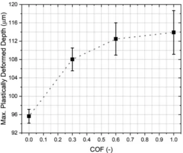
The positive effect of a lower friction coefficient was also observed in the numerical simulations, as presented in Fig. 15. In this figure, which considers only the homogeneous material, variations on the COF led to differences in the chip morphology and surface quality. The higher COF cases led to a thicker plastically deformed layer, measured from the free surface, which would be associated with higher de-formation and residual stresses and lower surface integrity after the cutting process.
3.4. Chip surface characterization – secondary shear zone
Fig. 16 presents an SEM image and the corresponding EDS ele-mental mapping of a chip surface (side in contact with the tool) of Astaloy 85Mo with the addition of 2 wt% MoS2,after orthogonal cut
under a cutting speed (vc) of 32 m/min and depth (d) of 0.15 mm. The
results evidence the formation of a transferred layer of FeeMoeS, which is produced by the deformation and migration of sulfides along the chip surface. This superficial tribolayer reduces the material sticking and the friction force at the secondary zone. The presence of superficial cracks is a result of the large plastic deformation through the chip thickness.
Fig. 17presents 3D and 2D optical profilometry analyses of the ef-fect of solid lubricant addition on the surface finish after orthogonal cutting. Unreinforced Astaloy 85Mo presents material detachment produced by adhesion, as observed from the 3D surface profile (Fig. 17a). Adhesion induces material transfer and anisotropic texture that increases the 2D profile roughness due to the presence of deeper valleys. The material detached and transferred to the tool surface ex-plains the built-up edge formation and the higher friction for this sin-tered sample [40]. Astaloy 85Mo with the addition of 2 wt% MoS2
shows a 3D surface profile with negligible presence of material de-tachment and texture at the cutting direction (Fig. 17b). The 2D profile, without deep valleys, evidence low roughness and good surface finish due to the sulfide addition. A link between coefficient of friction and surface finish was also observed by the numerical simulations, in which the maximum plastically deformed depth (Fig. 15) was lower for lower COFs.
Table 3summarizes the roughness parameters of the chip surface for the different sintered samples. Results indicate a significant differ-ence in the roughness parameters of the plain Astaloy 85Mo, in com-parison with samples with MoS2addition. The material detachment of
Astaloy 85Mo increases the maximum valley depth (Sv) and the texture anisotropy. These superficial defects also influence the other roughness parameters that include the peak to valley ratio, i.e. the average mean height (Sa) and the root mean square (Sq). The roughness parameters were significantly lower for both 2 and 4 wt % solid lubricant contents. However, the highest addition, 4 wt % MoS2exhibits a slight reduction
of the roughness parameters, which is in agreement with the lower cutting forces showed for the cutting depth of 0.20 mm, due to the additional amount of sulfides.
4. Conclusions
Orthogonal cutting tests were carried out under a speed of 32 m/ min and cutting depths of 0.15 mm and 0.20 mm, to analyze the effect of 2 and 4 wt% MoS2addition on the cutting forces and surface finish of
SPS sintered Astaloy 85Mo steel. FEM simulation and experimental
Fig. 15. Influence of the coefficient of friction on the plastically deformed depth after the cutting process for the homogeneous microstructure. Higher COF promotes deeper plastically deformed regions.
Fig. 16. SEM micrograph and EDS mapping of the chip surface showing tribofilm formation for Astaloy 85Mo ‒ 2 wt% MoS2under speed 32 m/min and depth
results show that the addition of solid lubricant is advantageous to the cutting performance:
1. Astaloy 85Mo sintered material exhibits low hardness and high plastic deformation that contribute to built-up edge formation and excessive adhesion and material detachment. This behavior results in high radial and tangential cutting forces.
2. The addition of 2 wt% MoS2produces a microstructural
modifica-tion by the formamodifica-tion of irregular dark iron-sulfides that provide stress intensity points. This microstructure intensifies stresses and reduces the cutting forces. For samples sintered with 4 wt % MoS2,
an additional lighter and round FeeMo phase is formed and con-tributes with additional stress concentration and cutting force re-duction at the higher cutting depth of 0.20 mm.
3. Dark irregular iron sulfides are extruded by high plastic strain through the chip thickness, which enables shear and movement towards the chip surface. The low shear resistance of these sulfides increases the cutting efficiency and the formation of a well-defined curled chip.
4. The formation of a transferred layer on the chip surface (side in contact with the tool) contributes with the lower tangential friction force at the chip-tool interface, due to sticking reduction at the secondary shear zone.
5. Experimental and numerical analyses were able to link the influence of COF with the quality of surface finishing after machining, in-dicating that lower COF produces better quality finishing. 6. The sulfides present in the metal matrix acted as stress
con-centrators, as observed in the numerical and experimental analyses. In both, cracks nucleated as a result of the sulfides.
Acknowledgments
The authors would like to acknowledge the Brazilian research sup-port agencies: Sao Paulo Research Foundation (FAPESP) Grant number 2016/18014-6 and the National Council for Scientific and
Technological Development (CNPq).
References
[1] Perez I, et al. Effect of of cutting speed on surface integrity integrity face milled 7050-T7451 aluminium workpieces. Procedia CIRP 2018;71:460–5.
[2] Pu CL, Zhu G, Yang SB, Yue EB, Subramanian SV. Effect of dynamic recrystallization at tool-chip interface on accelerating tool wear during high-speed cutting of AISI1045 steel. Int J Mach Tool Manuf 2016;100:72–80.
[3] Diniz AE, De Oliveira AJ. Optimizing the use of dry cutting in rough turning steel operations. Int J Mach Tool Manuf 2004;44(10):1061–7.
[4] Liu R, Eaton E, Yu M, Kuang J. An investigation of side flow during chip formation in orthogonal cutting. Procedia Manuf. 2017;10:568–77.
[5] Sutter G, Ranc N. Temperature fields in a chip during high-speed orthogonal cut-ting-An experimental investigation. Int J Mach Tool Manuf 2007;47(10):1507–17. [6] Sreejith PS, Ngoi BKA. Dry machining: machining of the future. J Mater Process
Technol 2000;101(1):287–91.
[7] Maurotto A, Tsivoulas D, Gu Y, Burke MG. Effects of machining abuse on the surface properties of AISI 316L stainless steel. Int J Press Vessel Pip 2017;151:35–44. [8] Medina-Clavijo B, Saez-de-Buruaga M, Motz C, Soler D, Chuvilin A, Arrazola PJ.
Microstructural aspects of the transition between two regimes in orthogonal cutting of AISI 1045 steel. J Mater Process Technol 2018;260:87–96.
[9] Bahi S, Nouari M, Moufki A, El Mansori M, Molinari A. A new friction law for sticking and sliding contacts in machining. Tribol Int 2011;44(7–8):764–71. [10] Jianxin D, Lili L, Xuefeng Y, Jianhua L, Junlong S, Jinlong Z. Self-lubrication of Al 2
O 3/TiC/CaF 2 ceramic composites in sliding wear tests and in machining processes. Mater Des 2007;28:757–64.
[11] Hao M, Xu D, Wei F, Li Q. Quantitative analysis of frictional behavior of cupronickel B10 at the tool-chip interface during dry cutting. Tribol Int 2018;118:163–9. [12] Yuan J, Fox-Rabinovich GS, Veldhuis SC. Control of tribofilm formation in dry
machining of hardened AISI D2 steel by tuning the cutting speed. Wear 2018;402(403):30–7.
[13] Singer IL, Fayeulle S, Ehni PD. Wear behavior of triode-sputtered MoS2 coatings in dry sliding contact with steel and ceramics. Wear 1996;195(1–2):7–20. [14] Dai M, Zhou K, Yuan Z, Ding Q, Fu Z. The cutting performance of diamond and
DLC-coated cutting tools. Diam Relat Mater 2000;9(9–10):1753–7.
[15] Bobzin K. High-performance coatings for cutting tools. CIRP J Manuf Sci Technol 2017;18(2016):1–9.
[16] Sugihara T, Singh P, Enomoto T. Development of novel cutting tools with dimple textured surfaces for dry machining of aluminum alloys. Procedia Manuf. 2017;14:111–7.
[17] Feng Y, Zhang J, Wang L, Zhang W, Tian Y, Kong X. Fabrication techniques and cutting performance of micro-textured self-lubricating ceramic cutting tools by in-situ forming of Al2O3-TiC. Int J Refract Metals Hard Mater 2017;68:121–9. [18] Ordoñez MFC, Farias MCM, Machado IF, Souza RM. Effect of tungsten carbide
addition on the tribological behavior of Astaloy 85Mo powder consolidated via spark plasma sintering. Tribol Int 2018;127:313–23.
[19] Hammes G, et al. Effect of hexagonal boron nitride and graphite on mechanical and scuffing resistance of self lubricating iron based composite. Wear
2017;376(377):1084–90.
[20] Zhou J, Ma C, Kang X, Zhang L, Li Liu X. Effect of WS2particle size on mechanical properties and tribological behaviors of Cu-WS2composites sintered by SPS. Trans. Nonferrous Met. Soc. China English Ed 2018;28(6):1176–85.
[21] Liu X, et al. Tribological behavior of M50-MoS2self-lubricating composites from 150 to 450 °C. Mater Chem Phys 2017;198:145–53.
[22] Mahnama M, Movahhedy MR. Application of FEM simulation of chip formation to stability analysis in orthogonal cutting process. J Manuf Process
2012;14(3):188–94.
[23] Laakso SVA, Niemi E. Using FEM simulations of cutting for evaluating the Fig. 17. 3D optical profilometry on the chip surface with 2D profile and texture isotropy in detail for
(a) Astaloy 85Mo and (b) Astaloy 85Mo ‒ 2 wt% MoS2.
Table 3
Roughness parameters of the chip surface of the different sintered samples. Analysis of the surface in contact with the tool. Arithmetic mean height (Sa), root mean square height (Sq), maximum valley height (Sv) and surface texture isotropy percentage (Str).
Material Sa (μm) Sq (μm) Sv (μm) Texture isotropy (%) Astaloy 85Mo 1.23 2.12 21.44 42.9
2 wt% MoS2 0.36 0.48 3.90 2.27 4 wt % MoS2 0.35 0.46 3.08 1.22
performance of different johnson cook parameter sets acquired with inverse methods. Robot Comput Integrated Manuf 2016:1–7.
[24] Bai W, Sun R, Roy A, Silberschmidt VV. Improved analytical prediction of chip formation in orthogonal cutting of titanium alloy Ti6Al4V. Int J Mech Sci 2017;133:357–67.
[25] Melkote SN, Liu R, Fernandez-Zelaia P, Marusich T. A physically based constitutive model for simulation of segmented chip formation in orthogonal cutting of com-mercially pure titanium. CIRP Ann - Manuf Technol 2015;64(1):65–8.
[26] Odum K, Soshi M. Surface formation study using a 3-D explicit finite element model of machining of gray cast iron. Procedia CIRP 2016;45:111–4.
[27] Ljustina G, Larsson R, Fagerström M. A FE based machining simulation metho-dology accounting for cast iron microstructure. Finite Elem Anal Des 2014;80:1–10. [28] Chagas GMP, Machado IF. Numerical model of machining considering the effect of MnS inclusions in an austenitic stainless steel. Procedia CIRP 2015;31(3):533–8. [29] Fukumasu NK, Souza RM. Numerical evaluation of cohesive and adhesive failure modes during the indentation of coated systems with compliant substrates. Surf Coating Technol 2014;260:266–71.
[30] Fukumasu NK, Bernardes CF, Ramirez MA, Trava-Airoldi VJ, Souza RM, Machado IF. Local transformation of amorphous hydrogenated carbon coating induced by high contact pressure. Tribol Int 2018;124:200–8.
[31] Hooputra H, Gese H, Dell H, Werner H. A comprehensive failure model for crash-worthiness simulation of aluminium extrusions. Int J Crashcrash-worthiness
2004;9(5):449–63.
[32] Hedayat AA, Afzadi EA, Iranpour A. Prediction of the bolt fracture in shear using
finite element method. Structure (Lond) 2017;12:188–210.
[33] Hu M, Zhang J, Sun B, Gu B. Finite element modeling of multiple transverse impact damage behaviors of 3-D braided composite beams at microstructure level. Int J Mech Sci 2018;148:730–44.
[34] Furlan KP, de Mello JDB, Klein AN. Self-lubricating composites containing MoS2: a review. Tribol Int 2018;120:280–98.
[35] Dhanasekaran S, Gnanamoorthy R. Microstructure, strength and tribological be-havior of Fe-C-Cu-Ni sintered steels prepared with MoS2 addition. J Mater Sci 2007;42(12):4659–66.
[36] Oviedo JP, et al. In situ TEM characterization of shear-stress-induced interlayer sliding in the cross section view of molybdenum disulfide. ACS Nano 2015;9(2):1543–51.
[37] Son S, Lim H, Ahn J. Effects of the friction coefficient on the minimum cutting thickness in micro cutting. Int J Mach Tool Manuf 2005;45(4–5):529–35. [38] Zheng G, Xu R, Cheng X, Zhao G, Li L, Zhao J. Effect of cutting parameters on wear
behavior of coated tool and surface roughness in high-speed turning of 300M. Meas J Int Meas Confed 2018;125:99–108.
[39] Mohammed WM, Ng E, Elbestawi MA. Modeling the effect of compacted graphite iron microstructure on cutting forces and tool wear. CIRP J Manuf Sci Technol 2012;5:87–101.
[40] Atlati S, Haddag B, Nouari M, Moufki A. Effect of the local friction and contact nature on the Built-Up Edge formation process in machining ductile metals. Tribol Int 2015;90:217–27.