Science Arts & Métiers (SAM)
is an open access repository that collects the work of Arts et Métiers Institute of
Technology researchers and makes it freely available over the web where possible.
This is an author-deposited version published in: https://sam.ensam.eu Handle ID: .http://hdl.handle.net/10985/9960
To cite this version :
Sabrine TRABELSI, Zoubeir BOUAZIZ, Guénaël GERMAIN, Anne MOREL - Numerical and Experimental Approach in Assisted Cryogenic Machining - In: the Sixth Conference on Design and Modeling of Mechanical Systems (CMSM2015), Tunisie, 2015-03 - Lecture Notes in Mechanical Engineering - 2015
Any correspondence concerning this service should be sent to the repository Administrator : [email protected]
© Springer International Publishing Switzerland 2015
M. Chouchane et al. (eds.), Design and Modeling of Mechanical Systems - II,
95 Lecture Notes in Mechanical Engineering, DOI: 10.1007/978-3-319-17527-0_10
Numerical and Experimental Approach
in Assisted Cryogenic Machining
Sabrine Trabelsi1, Zoubeir Bouaziz1, Guenael Germain2, and Anne Morel2
1 ENIS [email protected], [email protected] 2 ENSAM Angers {Guenael.germain,Anne.morel}@ensam.eu
Abstract. Understanding of local mechanisms chip forming during machining by
removal of material is difficult, to this end; a cutting finite element modelling is required. This study aims initially to model orthogonal cutting of Ti17 titanium al-loy in dry and cryogenic machining and in a second time to study the influence of the application of cryogen during machining on temperature fields and cutting forces in numerical simulation. An experimental study was also conducted to determine the mode of tool wear and the evolution of flank wear.
Keywords: Ti17, cryogenic assistance, numerical simulation, flank wear, cutting
forces.
1
Introduction
The use of titanium alloys in the field of aeronautics increases with time having regard to its compatibility with the composite reinforced with carbon fibers (CFRP), but the mechanical characteristics of the material such as its hardness machining, its low conductivity make it difficult to machine [1].To this end, the cryogenic machining assistance is one of the solutions to reduce the temperature at the tool / chip interface [2-3].
2
Experimental Approach
The machining tests were carried out by a CNC turning machine LEADWELL LTC25iL (2500 rev / min and 24 kW maximum). The acquisition system is com-posed of a Kistler dynamometer (9257B), the forces exerted on the quartz crystals are transformed into piezoelectric signals as a result of efforts to acquire the three components of the cutting force. The analog signals derived are amplified by a charge amplifier (Kistler 5019B). Thereafter, they are passed to an analog / digital converter. The evolution of the effort over time is provided by the software (Catman Easy).
96 S. Trabelsi et al. The uutting parameters for machining Ti17 are: depth of cut ap=1.5mm, feed f=0.3 mm/rev and cutting speed is 0.83 m/s.
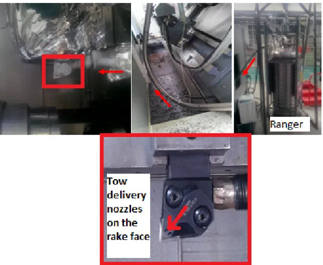
Fig. 1 Presentation of the cryogen’s flow and the cutting tool
The cutting tool used is Seco PCLNR JetStream 2525 M12 and a plate CNMG 120412-23 shade of H13A, the cutting edge α = 7 ° and the draft angle β = 6 °, the radius of curvature of 30 µm.
The liquid cryogen is stored in a ranger equipped with a 15 bar pressure imita-tor and is then injected on the rake face of the tool by two microbuses of 1.7 mm of diameter.
Cutting tests were performed for both lubrificated and cryogenic cutting of Ti17 to get cutting forces and flank wear.
The criterion of end of life of the tool is set at a flank wear VB=0.3mm and which was measured on constant time using a binocular microscope.
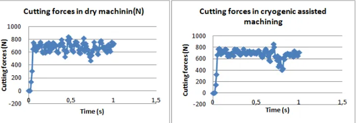
Fig. 2 Cutting forces and flank wear in both cryogenic assistance and wet machining
(Vc=50m/min, f=0.3mm/rev, ap=1.5mm)
It is noted that with the cryogenic support there was no reduction in cutting forces, but, on the other hand, the life of the tool has increased 3.65min lubrication 5min which may approximated by an increase of 27%. This may be explained by the decrease of the temperature.
A study was done to determine the mode of tool wear. • Degradation Mode of the Tool:
At first sight of the flank face, we think that the materiel of the tool is being re-moved by abrasion, to determine the mode of degradation; the cutting insert was examined under scanning electron microscope (SEM)SEM views of worn tools while turning Ti17 under VC = 50 m/min and f= 0.3 mm/rev.
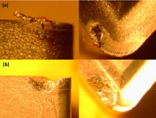
Fig. 3 Microscopic observation of the tool in cryogenic machining at (a) 1min and (b)
4min(f0.3mm/rev;ap1.5)
We found that the percentage of titanium that is the material of the machined piece increases over the time, so we conclude that the principal degradation mode of tool wear is adhesion.
893.47 847.29 0 200 400 600 800 1000 cryo lub
(a) Cutting forces (N)
5 3.65 0 2 4 6 cryo lub (b) Flank wear (mm) (a) (b)
98 S. Trabelsi et al.
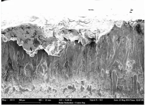
Fig. 4 SEM views of worn tools while turning Ti17 under f=0.3mm/rev and VC = 50 m/min
It is noted that there is a deposition of titanium on the flank face, this shows, that the tool wear is by adhesion, the material accumulated on the surface of the insert is removed after that.
3
Numerical Study
3.1
Model Description
2D model was developed on ABAQUS / explicit 6.11 to model orthogonal cutting. A lagrangian formalism was adopted. The boundary conditions are the embedding of the tool; the lower surface of the part has zero displacement Uy = 0, and the cutting speed is imposed on the left surface of the work piece V1=0.83m/s (Figure5).
The cutting tool is made of tungsten carbide which the parameters are presented in paragraph (2).
CPE4RT elements were used for a coupled temperature-displacement problem.
Fig. 5 Boundary conditions
U1=U2=U3= UR1=UR2=UR3=0 U2 =0 V1 =0.83 m/s chip passage piece
3.2
Law of Material Behavior
The behavior of the material was introduced by Johnson Cook constitutive law [4]. The equation generally used to describe the behaviour of the material is the BC law represents the yield stress of the material [Johnson 1983].
σ = (A+B εn
) (1+C lnε
ε ) [1- ( )
m
] (1) σ: equivalent stress vonMises;
ε: equivalent plastic strain;
ε : The equivalent plastic strain rate;
ε 0: The equivalent plastic strain reference rate; T: work piece temperature.
Tm: Melting
Tr: Room temperature
A, B, C, n and m are material constants determined from tests. The main advan-tage of this law is the decoupling of the terms of hardening and dependence on strain rate and temperature.
Table 1 The parameters of material behavior Law [5]
A(MPa) B(MPa) n
C
m Tr
(°C)
Tm
(°C)
1012 399 0.22
0.035
0.85
50
1650
3.3
Damage Law
The use of Lagrangian formalism requires the use of a criterion of separation be-tween the work piece and the chip which is expressed by a deterioration law John-son and Cook [3] (JohnJohn-son et al, 1985). The damage variable is:
D= Δ
(2)
Where the increment of plastic deformation in a no integration and
current equivalent plastic strain at break:
= [D1+D2 exp (D3 σ*)] (1+D4 ln ) [1+D5 T*] (3) D1, D2, D3, D4 and D5 are constants for the material σ *: The stress triaxiality rate defined by the P / σvm where P is the hydrostatic pressure and σvm rupture is reached when the damage variable D = 1. The corresponding element is
deacti-100 S. Trabelsi et al. vated. The variables and and T * = (T-Tr) / (Tm-Tr) are identical to those defined in the constitutive law (1).
Table 2 The parameters of the damage law [5]
D1 D2 D3 D4 D5 έ 0 -0.2 0.34 -0.5 -0.035 2.7 0.1
3.4
Modelling of Cryogenic Support
In our simulation, the elements of the damaged portion are removed after the pas-sage of the tool, it is the lower surface of the chip which rubs on the tool. To simu-late the application of the cryogenic jet on the rake face and in the lower surface of the chip detached from the tool, we use the programming software Python. The approach is as follows (fig7)
The tool rake face is a right which can determine the equation: ytool = a * xtool + b
Fig. 6 Determination of convection nodes
dx is the distance of remoteness of the nodes with respect to the cutting face from which convection is applied.
The nodes of the lower surface of the chip which are more in contact with the face of the tool ie if [xchip <((ychip-b) / a) -dx] then applied convection at this node.
In those nodes, convection is applied with a temperature sink of -196°C. (figure2)
Nodes of the lower surface of the chip in contact of the tool rake which its equation:
ytool = a * xtool + b Convection nodes Lower
surface of chip
Fig. 7 Steps of modeling the convection on the rake face
4
Results and Discussion
4.1
Temperature Fields
Ti17 titanium alloys generates segmented chip at the cutting speed of Vc=50m/min and the feed rate f = 0.3mm / rev.
The maximum temperature is 861.4° C in dry machining, while in cryogenic sup-port it decreases to 659°C in the secondary shear zone, that’s cooled the tool avoiding degradation modes at high temperatures and increases its life and provides
Fig. 8 Temperature fields in (a) dry and (b) cryogenic assisted machining
102 S. Trabelsi et al.
4.2
Cutting Forces
We note that with the cryogenic assistance, the fluctuation of the effort has de-creased, that’s decreases tool’s vibration, provides stable conditions machining and increases the tool life.
Fig. 9 Evolution dry cutting efforts, in cryogenic assistance on the rake face
Cutting efforts in cryogenic assisted machining in numerical model is 641.95N (f0.3; ap1) while in practice 595.3 N for the same conditions.Fcexp = Fcnum ±50N.
Cutting forces in cryogenic cooling are very close to dry machining efforts. This can be explained by the temperature of the primary shear zone that cryogen has not cooled.
5
Conclusion
• Cryogenic assistance on the rake face had no influence on the cutting forces, for against it decreases the temperature on the secondary shear zone during machining • The wear pattern observed is the adhesive wear
• The cryogenic support decreases flank wear and preserve a longer life time. This gain was quantified at 27% for f0.3 and p1,5.
References
[1] Dudzinski, D., Devillez, A., Moufki, A., Larrouquère, D., Zerrouki, V., Vigneau, J.: A review of developments towards dry and high speed machining of inconel 718 alloy. International Journal of Machine Tools and Manufacture 44(4), 439–456 (2004) [2] Uehara, K., Kumagai, S.: Chip formation, surface roughness and cutting force in
cryo-genic machining. Ann. CIRP 17(1), 68–74 (1968)
[3] Wang, Z.Y., Rajurkar, K.P., Fan, J.: Turning Ti–6Al–4V with cryogenic cooling. Trans. NAMRI/SME 24, 3–8 (1996)
[4] Johnson, G.R., Cook, W.H.: A constitutive model and data for metals subjected to large strains, strain rates and high temperatures. In: 7th Int. Symp. Ballistics, pp. 541– 547 (1983)
[5] Ayed, Y.: Approches expérimentales et numériques de l’usinage assisté jet d’eau haute pression: étude des mécanismes d’usure et contribution à la modélisation multi-physiques de la coupe (Décembre 5, 2013)