Science Arts & Métiers (SAM)
is an open access repository that collects the work of Arts et Métiers Institute of Technology researchers and makes it freely available over the web where possible.
This is an author-deposited version published in: https://sam.ensam.eu
Handle ID: .http://hdl.handle.net/10985/7419
To cite this version :
Rémy MARCHAL, Frédéric MOTHE, Louis DENAUD, Bernard THIBAUT, Laurent BLERON -Cutting Forces in basic and real life wood machining processes review, COST Action E35 20042008: Wood machining Micromechanics and fracture Holzforschung Vol. 63, n°2, p.157167 -2009
CUTTING FORCES IN BASIC AND REAL LIFE WOOD MACHINING PROCESSES 1
Review Paper 2
3
Rémy MARCHAL *,1, Frédéric MOTHE 2, Louis-Etienne DENAUD 3, 4
Bernard THIBAUT 4, Laurent BLERON 1 5
6
1 Arts et Métiers ParisTech, LABOMAP, 7
rue Porte de Paris, 71250 Cluny, France remy.marchal@cluny.ensam.fr 8
9
2 INRA, LERFOB, Champenoux, 54280 Seichamps, France 10
11
3 Université Paul Sabatier, LGMT-, 1 rue Lautréamont, 65016 Tarbes cedex, France 12
13
4 CNRS, EcoFoG, BP 709, 97379 Kourou Cedex, France 14
15
Abstract 16
17
The data available in the literature concerning wood cutting forces permit to build models or 18
to simulate the main wood machining processes (milling, sawing, peeling etc.). This approach 19
contributes to a better understanding of formation of wood surfaces and chips and the data 20
may be helpful to optimize cutting geometry, reduce tool wear, improve tool material, and to 21
size tool-machines. 22
The models may also be useful for industrial application in two ways: (1) providing 23
data to optimise the settings for a given operation (batch approach) and (2) building predictive 24
models that could be the basis of an online control systems for the machining processes 25
(interactive approach). A prerequisite for this is that numerous machining tests on different 26
wood materials are performed based on experiences with different kind of tools and 27
experimental devices. With potential industrial applications in focus, the emphasis of this 28
review was on the wood peeling process, which is a very demanding special case of wood 29
cutting. Though not so many industrial machines are equipped with expensive force sensors, 30
there is a lot of high quality information available about cutting forces which may be useful to 31
improve the scientific or technologic knowledge in wood machining. Alternative parameters, 32
such as vibration or sound measurements, appear to be promising substitutes in the praxis, 33
particularly to feed online control systems of any wood cutting process. 34
Keywords 35
cutting forces; online control; peeling process; physico-mechanical model; sound; vibrations; 36
wood industry; wood machining 37
38 39
Introduction 40
Why to measure cutting forces?
41
In the course of cutting process analysis, very often cutting forces are chosen as the main 42
output for physical description of the process. The other possibilities – like vibration, sound, 43
temperature, cutting power, deformation, surface quality and chip quality measurements – are 44
usually neglected. The main reason: measurement of cutting force is a powerful tool allowing 45
to build physico-mechanical cutting models for a better understanding of the phenomena 46
observed during cutting. These models permit to design or optimise processes, machines, 47
tools and wood preparation. 48
Cutting models have been first developed on scientific basis in order to describe the 49
formation and typology of chips related to given cutting forces levels (Kivimaa 1950; Franz 50
1958). The model of Merchant (1945), written for orthogonal cutting of metal, was adapted to 51
wood by McKenzie (1960). 52
Other models aiming at the analysis of the wood-tool interaction during machining, 53
were focusing more particularly on the influence of the cutting geometry (clearance and rake 54
angles), wood characteristics (species, density, moisture content, and temperature), and 55
processing parameters (cutting speed, depth of cut) on the level and stability of cutting forces 56
(Kivimaa 1950; McKenzie 1960). 57
Some authors preferred a mechanical approach based on the cutting forces and 58
evaluated the stress fields induced by the cutting process into the wood and into the tool, 59
considering the friction on the surface between the wood and tool. The resultant cutting forces 60
were divided into two categories: (1) forces exerted by the rake face and (2) forces exerted by 61
the clearance face of the tool (Thibaut 1988). When introducing the tool deflection (Decès-62
Petit 1996), the assessment of the cutting plan displacements became possible. 63
Some models have been elaborated to predict cutting forces, to understand the 64
mechanical behaviour of the materials tested (McKenzie 1962; Eyma et al. 2004) and other to 65
characterise the machinability of different wood materials (see Kivimaa et al. as quoted by 66
Scholtz and Troeger 2005). Another important target of these models was a diminishing 67
expensive experimentation efforts under consideration of all parameters of processing and 68
materials. 69
Cutting forces have been frequently measured to size motors for machine tools to 70
decrease energy consumption and to optimise processing parameters – such as cutting speed 71
(Liska 1950; Sinn et al. 2005) –, depth of cut (Axelsson et al.1993), feed rate (Ko et al. 1999) 72
and upward/downward milling (Palmqvist 2003; Goli et al. 2003). The cutting forces have 73
also been used to optimise the tool geometry, e.g. rake, wedge and clearance angles, tool edge 74
direction (Woodson and Koch 1970; McKenzie and Karpovich 1975; Komatsu 1976; Stewart 75
1977; Komatsu 1993; Boucher et al. 2004), and the tool head design (e.g. the chip space, 76
Heisel et al. 2004; Heisel et al. 2007). 77
Cutting forces have often been measured to compare the cutting properties of different 78
tool materials, e.g. steel, carbide, diamonds, thermal treated tools, and coated tools (Stewart 79
1991; Darmawan et al. 2008). Also the machined wood was in focus considering the grain 80
orientation and the structure (Axelsson 1994; Cyra and Tanaka 1999; Goli et al.2003), the 81
heterogeneity (Mothe 1988), the moisture content (Kivimaa 1950), the temperature of 82
steamed or frozen wood (Marchal et al. 1993, Lundberg and Axelsson 1993), the mature or 83
the juvenile wood (Gonçalves and Néri 2005), the tension or the normal wood (Vazquez-Cooz 84
and Meyer 2006), and the type of wood based materials. In the latter case, often modified 85
MDF (Kowaluk et al.2004) or not modified MDF (Ko et al. 1999) was investigated. 86
The avoidance of dust and noise, and the improvement of the productivity (reduction 87
the tool changing time, increase of the cutting speed, of the feed rate and of the cutting depth 88
for a given surface quality) were also frequently in focus. Important results were obtained 89
with this regards concerning predicting the tool edge wear (Fischer 1999; Fischer 2004), 90
online controlling the wear (Huang, Y.-S 1994; Cyra and Tanaka 1999), predicting the chip 91
geometry and fragmentation (Franz 1958), and online monitoring the wood surface quality 92
(Cyra and Tanaka 1999; Palmqvist and Johansson 1999; McKenzie et al. 2001). 93
In some specific cases, the measurements of cutting forces helped to quantify the 94
efficiency of auxiliary devices used to assist the cutting processes – e.g. ultrasonic-assisted 95
cutting (Sinn et al. 2004) – or to improve the use of a pressure bar (Mothe and Marchal 2001). 96
How to measure cutting forces?
97
Two main approaches are known to measure cutting forces. 98
(1) Direct measurements by sensors directly placed on the tool or in strategic points on the 99
frame. Strain gauges and piezo electric sensors are common. Strain gauges technology is 100
cheap but not always efficient. Dynamometers, specifically designed for measuring cutting 101
forces of wood, have some drawbacks especially for trials involving very small forces, which 102
is quite often the case in wood machining. Sometimes, the ground noise and the signal cannot 103
be differentiated. Such devices need a very meticulous set-up including an important 104
management of wiring. Nevertheless, they are highly sensitivity to temperature and moisture. 105
Another limiting factor is their low stiffness because they are based on deformation 106
measurements. Piezo electric sensors are more expensive and much stiffer. They are reliable 107
on several decades of forces values, are easy to maintain, and, – despite a drift of about 0.01 108
N/s in case of static test – are well adapted for dynamic and semi-static mechanical 109
measurements. 110
(2) Indirect measurement are also available, which are based on non-contact displacement 111
sensors with eddy current technology to measure distances, displacements. The forces are 112
then computed via an inverse function of transfer (Costes 2007). 113
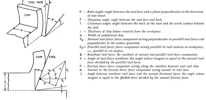
Which cutting force components to consider?
114
When measuring cutting forces, for the case of orthogonal cutting, the resultant force is 115
usually decomposed in two ways: (1) in two orthogonal components: parallel and normal 116
forces (Figure 1) and (2) in two facial components: rake and clearance forces (Figure 2). 117
The first decomposition seems often suitable from the technological point of view. 118
The parallel force gives information on the torque and consequently the energy consumption. 119
The normal force describes the plunging or cutting refusal tendency as well as the tool wear 120
(Palmqvist 2003). The thickness of the damaged layer arisen during planing is also described 121
(Hernandez and Rojas 2002). Force variations are linked up with the roughness of the wood 122
surface. 123
The second decomposition makes it possible to propose a model directly linking the 124
facial component forces to mechanical characteristics of wood. Such a model is much more 125
powerful than the first one for the physical understanding of the underlying phenomenon, and 126
at the same time, it is of some interest for optimising cutting geometry. On the other hand, 127
two main hypotheses are necessary to use such a facial decomposition: (1) The sharpness of 128
the tool is very good, i.e. the radius of the tool tip is low enough to neglect the “front” forces 129
on the tool tip compared to the two facial components. (2) There is only Coulomb friction 130
between tool and wood. 131
Franz (1958) and Kivimaa (1950) and many other authors favoured obviously the first 132
approach. Few authors adopted the second way: Dippon et al. (1999) for orthogonal cutting of 133
MDF, Thibaut (1988) and Thibaut and Beauchêne (2004) for the study of 0/90° cutting mode 134
on green wood (peeling or slicing). Fischer (2004) mixed the two approaches in order to 135
describe the phenomena at the mesoscopic scale just behind the cutting edge and, considering 136
the forces under and above the cutting line. This author proposed a global approach of wood 137
machining with specific trajectories of the tools into wood materials when milling, sawing or 138
drilling. 139
From the basic to the industrial praxis
140
Measurement of cutting forces during wood machining is nowadays easy to realise at 141
laboratory scale and physical models of cutting can be constructed which are capable of 142
simulating the process. Different authors developed specific devices. These are necessary: (1) 143
In the case of a batch processing for the prediction of machinability of some given wood 144
materials and/or setting-up of specific machining operation. (2) In the case of an interactive 145
processing to build a predictive model, then a monitoring system based on measurement of 146
forces. These can be applied to adjust online process parameters (the cutting speed and/or the 147
cutting geometry) based either on an open loop (help to the decision system for operators) or 148
on a closed loop (adaptive control) control. 149
Nevertheless, in this last case, cutting forces do not always appear to be the most 150
suitable inputs because of the specific and very expensive design of the machine-tools. 151
Moreover, the integration of gauges in the internal structure of a device often reduces a 152
machine’s rigidity. Substitute outputs for control purposes must then be found. 153
To illustrate all these aspects, this paper is focused on the peeling process because it is 154
an industrial process following a fundamental cutting mode (0°/90°). A direct transfer of the 155
results from the laboratory scale to the industrial one is possible. 156
The peeling process requires keeping very accurate settings all along the machining 157
operation. Actually, the cutting forces being the lowest among all wood processes (mode 158
0°/90°, green wood), the tool balance is very sensitive to any change – even minor – of 159
settings and of wood properties. Critical cutting plan displacements easily occur inducing 160
veneer thickness variation because of the high transverse deformability of green and often 161
heated wood blocks stressed by the knife. Moreover, the action of the pressure bar modifies 162
forces equilibrium and its settings interlink with the knife’s settings. In peeling process the 163
final product (the veneer) being the chip, a carefully setting of all parameters is very 164
important in order to obtain both a good quality chip and machined surface, but also to reach 165
as fast as possible the steady state and to keep it. 166
Model of cutting forces to simulate the process
167Mechanics of peeling process
168
Thibaut (1988) and Thibaut (1995) proposed a system of mechanistic models for describing 169
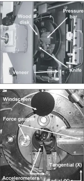
the basic processes in rotary veneer cutting. The experimental analyses were performed by a 170
microlathe (Figure 3). This device permitted to record cutting forces and to visualise the 171
lateral section of the piece of wood during the process (Butaud et al. 1995). The models of 172
Thibaut explained and reproduced most of the experimental observations resulting from 173
numerous peeling trials of various species like chestnut (Movassaghi 1985; Thibaut 1988), 174
Douglas-fir (Movassaghi 1985; Mothe 1988), oaks (Marchal 1989), beech, walnut and poplar 175
(Deces-Petit 1996), numerous tropical woods (Thibaut 1988; Beauchêne 1996). 176
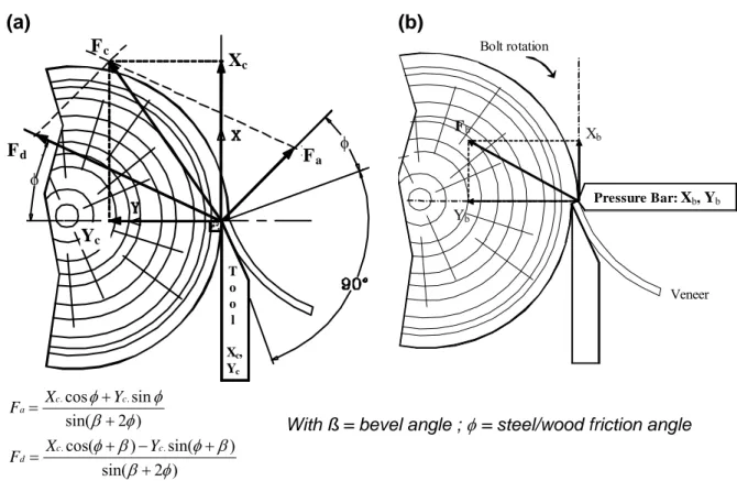
The main experimental observations may be summarised as follows after the analysis of 177
the forces exerted by the tool (the resultant rake force Fa, the resultant clearance force Fd) and 178
by the pressure bar (Fb), and also considering their respective tangential (or parallel) and 179
radial (or normal) components X and Y (Figure 2): 180
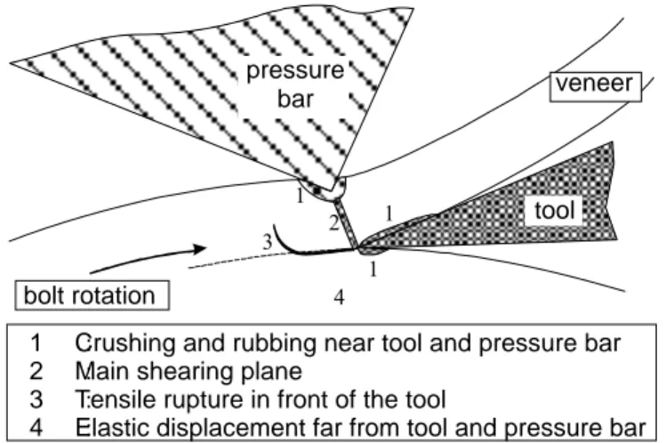
The chip flows above the rake face of the tool via a shearing deformation along a nearly 181
radial plane (zone 2 in Figure 4), and does not show any shortening as compared to cutting 182
length, which is in strong disagreement with classical metal machining experiments and 183
theories like that of Merchant. 184
The compression and rubbing action of the pressure bar – most of the experiments were 185
performed with a nosebar; the action of a round bar would be slightly different – and the 186
clearance face of the tool result in radial compressive stresses which can reach very high 187
values (crushing of the cells – zones 1 in Figure 4) near the contact zone, and remain in the 188
elastic domain farther from the tool (zone 4 in Figure 4). 189
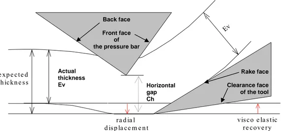
The radial wood displacement at the tip level leads to unexpected changes of the final 190
thickness of the veneer due to this compression state (Figure 5). 191
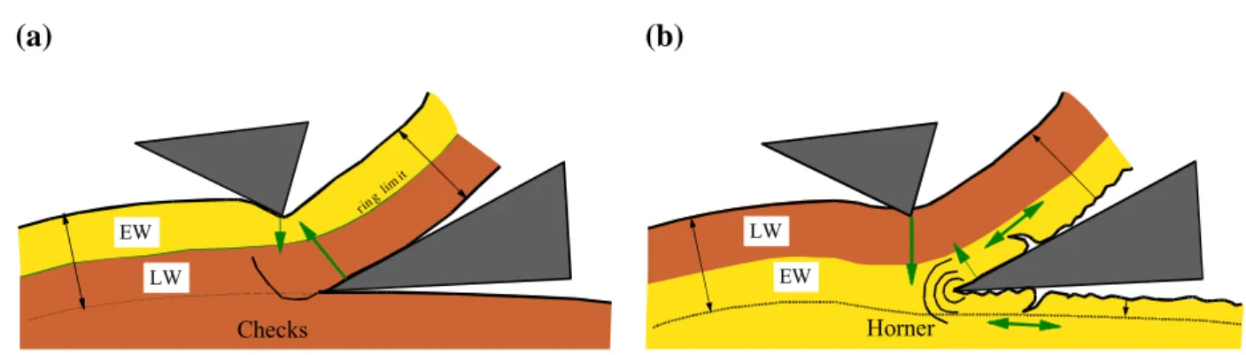
In front of the tool tip, the radial tensile stresses resulting from both tool and bar actions 192
may lead to lathe checks (in mode I), particularly for thick veneer and dense wood (zones 3 in 193
Figure 4, Figure 6a). 194
For lower thickness and softer wood, the tangential compression at the tool edge level 195
may lead to discontinuous cutting with alternation of wood compression and relaxation in 196
front of the tool tip. This behaviour is often called the Horner effect (Figure 6b). 197
Simulation of the peeling process
198
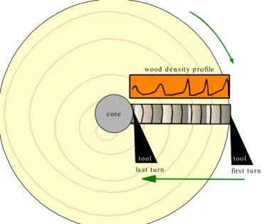
The models of Thibaut were embedded into a software for simulating the rotary cutting of a 199
heterogeneous wood (Mothe et al.1997). The simulation works on a radial basis: starting from 200
the initial conditions (tool edge tangential to the surface, veneer thickness = 0), the cutting 201
forces are computed for each rotation at the same angular position (Figure 7), as the tool 202
moves radially inwards. The radial wood displacement induced by the cutting forces is 203
therefore computed, allowing predicting the actual veneer thickness at each turn. 204
It was assumed that wood properties remain constant – at least in a short distance – in 205
both tangential and longitudinal directions and vary only along the radius. Beauchêne and 206
Thibaut (1996) showed that most of the mechanical properties of wet wood depend strongly 207
on the wood density and temperature for tropical homogeneous species. The stress-strain 208
curves in radial compression, in radial tension, and in radial/tangential shear are all supposed 209
to be predictable at a given temperature through the wood density profile from the tip of the 210
pressure bar to the inner core. 211
Force on the pressure bar (Fb) 212
The radial component of Fb, Yb, is related to the depth of wood crushed by the pressure bar 213
which is the difference between the actual veneer thickness Ev and the horizontal gap Ch. The 214
radial displacement is absorbed by the whole block of wood from the upper side of the veneer 215
to the peeling lathe spindle (not considering the bolt bending). 216
The radial force may be computed with an iterative procedure: For increasing values 217
of the load, the stress distribution is estimated along a plane uniformly loaded with the 218
formula of Timoshenko and Goodier (1951). The radial displacements of elementary portions 219
of wood are summed along the radius to compute the total wood displacement: The process is 220
repeated until the total displacement is close enough to the bar penetration Ev - Ch. 221
Finally, an experimental model based on the pressure bar settings and the friction 222
coefficient is applied for estimating the orientation angle of Fb and therefore the tangential 223
component Xb. Assuming that the compression load is identical on both the front and back 224
faces of the pressure bar, the total force is redistributed on both faces proportionally to the 225
respective lengths of contact, which are computed geometrically. 226
Force on the tool clearance face (Fd) 227
The clearance force Fd depends mainly on the amount and stiffness of wood crushed by the 228
clearance face. The depth and length of contact are computed geometrically based on the 229
actual veneer thickness, the peeling radius, and the clearance angle. The radial component is 230
then calculated by the same iterative procedure as for the pressure bar force. 231
However, experimental results show that Fd remains rather high even if the clearance 232
angle is large enough to minimise the contact. This can be explained by the crushing of cells 233
rolling back the tool edge and rubbing the clearance face on a short distance. This second 234
contribution to the radial component of Fd can be estimated by the product of the contact 235
length (supposed to be constant) and the stress generated by the cells crushing (supposed to be 236
equal to the end of the elastic phase of the stress-strain curve in radial compression). 237
With the radial component of the clearance force being known, the angle of inclination 238
of Fd (given by the friction coefficient between wet wood and metal) can be used to compute 239
the tangential component of the clearance force. 240
Force on the tool rake face (Fa) 241
The rake force Fa increases quite linearly with wood density and veneer thickness. It depends 242
mainly on the intensity of the stresses and their distribution along the main shearing plane. 243
In absence of a pressure bar, the radial force may be estimated by integrating along 244
the stresses along the shear plane (supposedly radial). Considering that the wedge angle is 245
usually close to 20°, the maximal shear deformation near the tool tip may be assumed to be 246
constant (around 35%) whatever the lathe settings are. An exponential decreasing function is 247
then used to describe the stress distribution and to compute the radial component of Fa. 248
In the presence of a pressure bar, the forces on both the back and front faces of the 249
bar have to be considered. The radial component of the back face force contributes positively 250
to the rake force, the veneer being compressed between the back face of the bar and the rake 251
face of the tool (this force is null if the angle between the cutting plan and the back face is 252
above 90°). On the other hand, the front face force contributes negatively by reducing the 253
stresses along the shearing plane. 254
Radial wood displacements due to the cutting forces
255
The radial forces on the tool and the pressure bar lead to radial displacement of the wood 256
block. As a main consequence, the veneer thickness (Ev) may be slightly different from the 257
expected thickness. 258
The actual thickness depends on the current radial displacement and on the 259
displacement resulted from the previous revolution. Assuming that the previous displacement 260
and the cutting forces are known, the new displacements generated at the tool tip level by the 261
radial components of the shearing force, the tool clearance force and the front face of the 262
pressure bar forcehave to be computed. The force on the back face of the nosebar is assumed 263
have no effect because it is equilibrated by the face force of the tool rake.In each case, this 264
task is performed by summing along the radius the displacements of elementary layers of 265
wood in accordance with the relationships between tension and compression stress-strain. 266
Main calculation loop
267
Considering that the cutting forces are needed for estimating the veneer thickness and that the 268
thickness depends on the cutting forces, an iterative procedure has to be applied. The 269
convergence is usually reached after less than five iterations for heterogeneous woods except 270
when the properties change abruptly (e.g. near an annual ring limit) or when the pressure bar 271
(being misplaced) leads the tool to plunge and rise alternately. 272
Veneer quality
273
The three main defects of a rotary cut veneer linked to the cutting process are lathe checks, 274
roughness due to the Horner effect, and thickness variations. Only the last one has been 275
actually predicted by the simulator, even if lathe checks and Horner effect could be predicted 276
easily through cutting forces and tensile properties of wood. 277
For heterogeneous wood species, the continuous changes in wood density tend to 278
make worse these defects. The most unfavourable case occurs when the wood density near the 279
pressure bar and near the tool are strongly different, as shown for the two main cases in figure 280
6 frequently occurring when peeling softwoods. 281
A virtual simulation of the peeling process is nowadays available to predict cutting 282
forces, and consequently the adapted settings for given wood species. However, this model 283
can be improved with better modelling of wet wood mechanical behaviour. With a view to 284
deliver a more general model of the chip formation during peeling at the mesoscopic scale, 285
Bonin (2006) attempted to implement a thermo-mechanical simulation of metal turning 286
(Cordebois 1994; Ali, F. 2001) to wood peeling. An adaptation of the thermo mechanic model 287
of Oxley (1989) has been tested based on a law of wood orthotropy (called the Bauschinger 288
effect; asymmetry of the mechanical behaviour in compression and tension) and considering 289
the deformation speed. This approach was unsuccessful because all the analytical models of 290
the chip formation for metals are based on laws describing elastoplastic behaviour at high 291
deformations. After having performed a great number of mechanical tests on beech green 292
wood in transverse directions, Bonin (2006) concluded that hyperelasticity and 293
compressibility of green wood like elastomers (Laraba-Abbes 1998) caused the differences. 294
Bonin (2006) also built a new model relying on simplified assumptions (e.g. neglecting the 295
increase of temperature during chip formation and the orthotropy in the transverse plan) based 296
on thirty micropeeling tests. In this model, the slope of the cutting zone was in agreement 297
with the experiments. Furthermore, forces occurring on the rake face of the tool were 298
correctly predicted: for more than 95% of the predicted forces, the gap between experimented 299
and predicted results was less than 20%. 300
Dynamometric approach for optimising the process 301
From this comprehensive description of the veneering process, several practical rules can be 302
highlighted which are directly applicable to industrial processes. Just considering the two 303
decompositions of Fc, the resultant cutting force exerted by the tool, the 4 components provide 304
useful practical information on the process in progress: 305
(1) Xc: its mean value determines the lathe motor torque value. It must be as small as 306
possible. Standard variation of Xc is linked to the amplitude and possibly the frequency of 307
lathe checking. 308
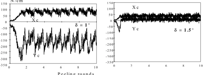
(2) Yc is linked to the tool tip position: a negative value expresses a cutting refusal 309
tendency when a positive one indicates a tool plunging tendency. In the normal case, the best 310
settings are obtained when the tool dives a little (low positive Yc value); the cutting plan is 311
then slightly lower than the theoretical one. As can be seen in Figure 8, a very small change 312
on clearance angle can then induce huge effect upon the tool equilibrium, especially for very 313
small veneer thicknesses (Marchal and Negri 1997). 314
(3) The ratio Fa/Fd describes the tool balance and also the wear pattern. In the normal 315
case, Fa/Fd is in the range of 2 to 3. Fa and Fd, are computed as illustrated in Figure 2. These 316
two forces are, respectively, a function of the veneer thickness and of the clearance angle. It is 317
quite easy to act on the clearance angle to reach the right ratio. This ratio must be as 318
insensitive as possible to cutting speed variation. There are for a given wood species two 319
domains: one for low cutting speed and one for high cutting speed. At high speed, the 320
clearance angle should be increased in order to avoid the huge increase of Fd (Figure 9 in the 321
case of walnut) due to the “Maxwell effect” and then to maintain the good balance of the tool. 322
Cutting speed and clearance angle are interlinked settings. Remark to the Maxwell effect: 323
Under high deformation speeds, free water contained in cells being only parthly evacuated 324
from the maximum stress area, the free water still remaining induces an apparent increase in 325
rigidity through Young’s modulus because of its incompressibility (Costes and Larricq 2002). 326
(4) All the mean values and the variation of forces must be maintained at a level as low as 327
possible in order to improve tool-life (minimizing the wear of the tool and machine fatigue). 328
Considering also the pressure bar, (1) The ratio Yb/Fa can be used to survey the pressure 329
bar efficiency for reducing lathe checking (Thibaut 1988). (2) The sum Xc+Xb should be 330
minimized to decrease the power consumption and (3) the sum Yc + Yb should be minimized 331
to decrease the flexion of the wood block at the end of the process. 332
These measurements and calculation are very useful for the process optimisation at the 333
laboratory scale. However, there are not yet industrial machines equipped with force sensors 334
which make possible the application of this knowledge neither for basic optimisation nor for 335
online control of the process (Lemaster et al.2000a). Nevertheless, for high value added 336
products, the process could be feasible. 337
Cutting forces and alternative outputs to develop interactive processing
338Power consumption
339
Some alternative inputs were also investigated. The nearest measurement to forces is probably 340
power consumption. Despite the fact that it is quite easy to implement directly a spindle to 341
measure the power consumed by the cut, this information is significantly less pertinent. 342
According to Lemaster et al. (2000a), this measurement integrates both the cutting forces and 343
the dynamic aspects of the machine. 344
Artificial vision
345
Operators on CNC often characterise the status of the process by visual inspection. Many 346
defects of the machined surface or tool wear can be seen directly. Unfortunately, according to 347
Januten (2002), direct methods to measure tool wear (also including computer vision) have 348
not yet proven to be very attractive economically and technically. Lemaster and Stewart 349
(2005) have developed a software able to distinguish different random defects from an optical 350
profilometer signal. The algorithm proposed is based on fuzzy logic and Wavelets. This 351
approach seems very promising, but it is still not yet fully developed. 352
Acoustic emission
353
Several authors also applied acoustic emission (AE) as input data. AE is the stress waves (low 354
energy and very high frequency i.e. from 100 kHz up to 1000 kHz) produced by the sudden 355
internal stress redistribution of a material caused by changes in its internal structure (crack 356
opening or growing, fibre breakage, etc.). Lemaster et al. (1982), Lemaster and Kato (1991), 357
and Murase et al. (2004) proved the great potential of this technique to monitor wood cutting 358
processes. According to the accepted indicators (Root Mean Square - RMS, count rate, 359
cumulative count rate, etc.), AE is sensitive to the chip formation mechanism (shearing plan, 360
sliding areas, cracks, splits etc.). However, Lemaster et al. (2000a) underlined the limitation 361
of this technique which is the high sensitivity to background noise due to the device 362
components such as roller bearings. Adding the high damping character of wood materials, it 363
is necessary to place sensors very closed to the cutting area, which is often not applicable in 364
industry. 365
Sound and vibrations
366
Experienced operators are very sensitive to sound or vibrations emitted by the process of 367
milling or sawing (Marchal et al. 2000). Only a few works were carried out with acoustic or 368
vibratory sensors as sources of information for wood machining. Nagatomi et al. (1999) found 369
a high correlation between probability of sound pressure level (SPL) larger than a suitable 370
threshold and surface roughness of peeled veneers of sugi. However, this relation was 371
obtained within a very large domain of frequencies (some Hz to 100 kHz) which is not 372
congruent with the operator’s ability with an audible range from 20 Hz to 20 kHz. In 373
numerous other works based on AE or SPL measurements to build an online control system 374
(Tanaka et al. 1997; Nagatomi et al.1993; Murase and Harada 1995), the threshold value 375
determination has never been clearly explained. This value is always more or less linked to 376
experimental settings applied (device, wood species, cutting conditions, moisture content, 377
etc.) which is not enough flexible to meet industrial requirements. Iskra and Tanaka (2006) 378
used dynamical thresholds to analyse (one-third octave band analysis) both SPL and sound 379
intensity during routing of Japanese beech. This constituted a great improvement of the 380
approach previously described because the criterion was polyvalent and consequently better 381
adapted to industrial environment constraint. 382
Iskra and Tanaka (2005) obtained a significant and high correlation coefficient 383
between surface roughness and sound intensity allowing them to adapt feed rate during 384
routing with regard to the value of sample grain angle. However, the frequency band selected 385
for computation was probably only optimal for the experimental setup considered. Lemaster 386
et al. (2000b) used accelerometers and obtained similar results for tool wear monitoring 387
during routing. Instead of a global RMS value (computed on a large frequencies domain), the 388
authors proposed power spectrum density (PSD) as criterion to determine the most promising 389
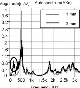
band for computation. The great potential of spectral analysis was confirmed by Denaud et al. 390
(2005). During peeling, the authors identified a peak on fast Fourier transform (FFT) spectra 391
(obtained from both microphone and accelerometers as indicated in Figure 10). It corresponds 392
to the vibratory signature of the average lathe check frequency of the veneer. This 393
phenomenon is almost periodic for homogeneous species. However, the peak detection would 394
be only possible by characterising the mechanical behaviour of the lathe which is a delicate 395
and an expensive operation. To bypass this difficulty, Denaud et al. (2007a) developed a 396
method to identify the signature of lathe checks on the temporal signal emitted from the same 397
sensors. This needs only a local RMS averaging via a peak detection algorithm which did not 398
require any threshold (see Figure 11). This approach seemed very promising to get check 399
distributions along the veneer, however, its efficiency for slightly checked veneers was not 400
characterised. 401
To sum up, vibration or sound measurements seem to be the most promising ways to 402
substitute measurements of cutting forces in a search for an online control system of a cutting 403
process. However, there are some ambiguities concerning a threshold, a correlation 404
coefficient, a frequency band domain or a peak on a spectral analysis. Hitherto, empirical and 405
preliminary limits are set with this regard. 406
As a response, Denaud et al. (2007b) initiated new experiments. These authors tried to 407
avoid any check formation and estimated PSD from a “reference cutting trail” under 408
conditions of a high pressure rate of the pressure bar (20% of the veneer thickness here). In 409
this manner, they took account of the dynamical behaviour of their device. Such settings 410
produced inevitably unacceptable variations of the veneer thickness which, however, did not 411
affect notably the PSD. 412
The ratio between measured and reference signal helped avoid natural frequencies of 413
the lathe. By this way, the default signature characterisation was greatly simplified as shown 414
in Figure 12 for the same domain of frequencies. The highest peak was at 152 Hz which 415
corresponds to an average distance of almost 3.3 mm between two consecutive checks. 416
Moreover, according to the results of Denaud et al. (2007b), this approach is also suitable for 417
relatively low pressure rates. In the end, this could lead to an online control of the pressure 418
rate of the pressure bar which is always a compromise to obtain a veneer with small lathe 419
checks and constant thickness. 420
Conclusion 421
For a long time, cutting force measurement has been the only successful and most powerful 422
measurement for producing output data for advanced analytical research on wood machining 423
processes. It is still matchless and helps improve knowledge about wood surface formation 424
and tool wear. Its main asset is that it takes into consideration the contact between tool and 425
wood and thus enables computation of the strains inside the wood pieces, the wood chips, and 426
the tools. However, cheaper sensors with more operating comfort are needed in the industrial 427
praxis. Against this background, accelerometers and microphones, which can be integrated 428
easily into the machine, are promising sensors for the near future. On the other hand, the 429
signal treatment is more difficult in the case of these sensors. 430
Measuring wood cutting forces makes a sense definitively for basic research. The 431
same is true in industrial applications, particularly in batch processes. In such cases, 432
preliminary tests on specific machining benches are necessary in order to optimise cutting 433
geometry and any other cutting parameters, before launching a new production. 434
References 435
Ali, F. (2001) Modélisation et simulation thermomécanique de la coupe des métaux. ENSAM 436
PhD thesis, Paris, 284 p. 437
Axelsson, B.O.M. (1994) Lateral cutting force during machining of wood due to momentary 438
disturbances in the wood structure and degree of wear of the cutting tool. Holz Roh Werkst 52 439
(3): 198 - 204 440
Axelsson, B.O.M., Grundberg, S.A., Grönlund, J.A. (1993) Tool wear when planning and 441
milling. Measurement methodology and influencing factors. Proceeding of IWMS 11, May, 442
25-27 1993, 159-176 443
Beauchêne, J. (1996) Evolution du comportement mécanique du bois vert avec la 444
température. Application à l'étude du déroulage et du tranchage de quelques bois guyanais. 445
ENGREF PhD thesis, Montpellier, April 1996, 164 p+ann. 446
Beauchêne, J., Thibaut B. (1996) Influence de la température sur le comportement mécanique 447
du bois vert : application à l'étuvage d'essences guyanaises en vue du déroulage. Proceedings 448
of “Quatrième Colloque Sciences et Industries du Bois”, Nancy, 11-13 septembre 1996, 449
p 299-306. 450
Bonin, V. (2006) Modélisation analytique de la déformation du copeau Durant le procédé de 451
déroulage de hêtre, Thèse de Mécanique, ENSAM, 273 p. 452
Boucher, J., Méausoone, P.-J., Perrin, L. (2004) Effect of diamond tool edge direction angle 453
on cutting forces and tool wear during milling of Medium Density Fiberboard and 454
particleboard. Proceedings of the 2nd International Symposium on Wood Machining, Vienna 455
July 5-7, 2004, 399-407 456
Butaud, J.C., Decès-Petit, C., Marchal,R. (1995) An Experimental Device for the Study of 457
Wood Cutting Mechanisms : the Microlathe. Proceedings of the 12th International Wood 458
Machining Seminar, October 2-4, 1995, KYOTO (Japan) 459
Cordebois, J.P. (1994) Viscoplastic modelling of cutting in turning, Journal of materials 460
processing technology, 1994, vol. 41, pp. 187-200 461
Costes, J.-P. (2007) Measurements without contact of vibration during milling : two exemples 462
of applications in machining operations monitoring. Lecture in Training School of COST 463
Action E35, Cluny, 5-7 december 2007 464
Costes, J.-P., Larricq P. (2002) Towards high cutting speed in wood milling. Ann. For. Sci. 59 465
(2002) 857-865 466
Cyra, G., Tanaka, C. (1997) The effects of grain orientation on routing surface, finish, cutting 467
forces and acoustic emission. Proceeding of IWMS 13, June 17-20, 1997, 323 - 331 468
Darmawan, W, Usuki, H., Quesada, J. Marchal, R. (2008) Clearance wear and normal force 469
of TiN-coated P30 in cutting hardboards and wood-chip cement boards. Holz Roh Werkst 66: 470
89–97 471
Decès-Petit C. (1996) Etude des phases transitoires au cours du déroulage de bois. ENSAM 472
PhD thesis, Cluny, October 1996, 120 p+ann. 473
Denaud, L.-E. (2006) Analyses vibratoires et acoustiques du déroulage. ENSAM PhD thesis, 474
Cluny, November 2006, 236 p., 2 annexes 475
Denaud, L.E., Bléron, L., Ratle, A., Marchal, R. (2005) Vibro-acoustic analysis of wood 476
peeling process: temporal and spectral analysis, Proceedings of the 17th IWMS, Sept. 26-477
28th, Rosenheim (Germany), pp. 55-65. 478
Denaud, L.E., Bléron, L., Ratle, A., Marchal, R. (2007 a) Online control of wood peeling 479
process: Acoustical and vibratory measurements of lathe checks frequency. Ann. For. Sci. 480
64:569–575. 481
Denaud, L.E., Bléron, L., Ratle, A., Marchal, R. (2007 b) On-line measurement of the average 482
lathe checks frequency of peeled veneers.Proceedings of the 3rd International Symposium on 483
Wood Machining, Lausanne May 21-23, 2007, 77-80. 484
Dippon, J., Ren, H., Ben Amara, F., Altintas, Y. (1999) Orthogonal cutting mechanics of 485
Medium Density Fiberboards. Proceeding of IWMS 14, September 12-19, 1999, 31-40 486
Eyma, F., Méausoone, P.-J., Martin, P. (2004) Study of the properties of thirteen tropical 487
wood species to improve the prediction of cutting forces in mode B. Ann. For. Sci. 61:55-64 488
Fisher R. (1999) Wood cutting simulation – A program to experiment without a machine. 489
Proceeding of IWMS 14, September 12-19, 1999, 553-562 490
Fisher R. (2004) Microprocesses at cutting edge – Some basics of machining wood. 491
Proceedings of the 2nd International Symposium on Wood Machining, Vienna July 5-7, 2004, 492
191-202 493
Franz, N.C. (1958) An analysis of the wood-cutting process, Univ. of Michigan Press, Ann. 494
Arbor., Mich., 1958. 495
Goli, G., Marchal, R., Uzielli, L., Negri, M. (2003) Measuring cutting forces in routing wood 496
at various grain angles. Study and comparison between u- and down-milling techniques, 497
processing Douflas-fir and oak. Proceedings of IWMS 16, Matsue, August 24-30, 2003 127-498
137 499
Gonçalves, R.,Néri, A. C (2005) Orthogonal cutting forces in juvenile and mature Pinus taeda 500
wood. Sci. agric. (Piracicaba, Braz.), vol.62, n°.4, Piracicaba July/Aug. 2005, 310-318 501
Heisel, U., Tröger, J., Martynenko, S. (2004) Aspects on high-performance cutting with 502
machining centres. Proceedings of the 2nd International Symposium on Wood Machining, 503
Vienna July 5-7, 2004, 161-173 504
Heisel, U., Martynenko, S., Schneider, M. (2007) Influence of chip space filling on cutting 505
forces in high-speed milling of wood and derived timber products. Proceedings of the 3rd 506
International Symposium on Wood Machining, Lausanne May 21-23, 2007, 51-54 507
Hernández, R.E., Rojas, G. (2002) Effects of knife jointing and wear on the planed surface 508
quality. of sugar maple wood. Wood Fiber Sci 34:293–305 509
Huang, Y.-S., (1994) Cutting force components in orthogonal cutting parallel to the grain 510
(90-0). II. Effect of feed lengths. Mokuzai Gakkaishi 40(10): 1059-1066 511
Iskra, P., Tanaka, C. (2005) The influence of wood fiber direction, feed rate, and cutting 512
width on sound intensity during routing. Holz Roh Werkst 63(3):167-172. 513
Iskra,P., Tanaka, C. (2006) A comparison of selected acoustic signal analysis techniques to 514
evaluate wood surface roughness produced during routing, Wood Sci. Technol. 63(3):247-515
259. 516
Januten, E. (2002) A summary of methods applied to tool condition monitoring in drilling, 517
International Journal of Machine Tools and Manufacture 42(9):997-1010. 518
Kivimaa, E. (1950) The cutting force in woodworking. Publication number 18. The State 519
Institute for Technichal Research, Filand, Helsinski, 103 p. 520
Ko, P., McKenzie, W., Cvitkovic, R., Robertson, M.F. (1999) Parametric studies in 521
orthogonal machining MDF. Proceeding of IWMS 14, September 12-19, 1999, 1-12 522
Komatsu, M. (1976), Machine boring properties of wood. II. The effects boring conditions 523
on the cutting forces and the accuracy of finishing, J. Jap. Wood Res. Soc. 1976 22(9): 524
491-497. 525
Komatsu, M. (1993) Machining performance of a router bit in the peripheral milling of wood 526
I. Effects of the radial rake angle of the peripheral cutting-edge on the cutting force and 527
machined-surface roughness. Mokuzai Gakkaishi, 39(6), 628-635 528
Korwaluk, G., Dziurka, D., Beer, P., Sinn, G., Stanzl-Tschegg, S. (2004) Influence of 529
ammonia on particleboard propertie. Proceedings of 2nd International symposium on wood 530
machining, Vienna Austria, 5-7 July 2004, 459-465 531
Laraba-Abbes, F. (1998) Etude des comportements hyperélastiques et viscoélastiques de deux 532
élastomères de type NR et PDMS par extensométrie optique bidimensionnelle. Thèse 533
mécanique et matériaux. Paris : Ecole Centrale de Paris, 1998, 295 p. 534
Lemaster, R.L., Klamacki, B.E., Dornfeld, D.A. (1982) Analysis of Acoustic Emission in 535
Slow Speed Wood Cutting, Wood Sci.15(2):150-160. 536
Lemaster, R.L., Kato ,K. (1991) Generation of Acoustic Emission during chip formation, 10th 537
IWMS, oct., pp. 146-151. 538
Lemaster, R.L., Lu, L., Jackson, S. (2000)(a) The use of process monitoring techniques on a 539
CNC wood router – Part 1. Sensor selection, Forest Product Journal 50(7/8):31-38. 540
Lemaster, R.L., Lu, L., Jackson, S. (2000)(b) The use of process monitoring techniques on a 541
CNC wood router – Part 2. Use of a vibration accelerometer to monitor tool wear and work 542
piece quality, Forest Product Journal. 50 (9): 59-64. 543
Lemaster, R.L., Stewart, J.S. (2005) Research in Process Monitoring of Surface Quality 544
Conducted at the North Carolina Sate University Wood Machining and Tooling Research 545
Program, Proceedings of the 17th IWMS, Sept. 26-28th, Rosenheim (Germany), pp. 450-467. 546
Liska, J. A. (1950) Effect of rapid loading on the compression and flexural strength of wood. 547
Forest Products Laboratory Report 1767. 548
Lundberg, A.S., Axelsson, B.O.M. (1993) Studies of the cutting forces and the chip formation 549
process when cutting frozen wood. Proceeding of IWMS 11, May, 25-27 1993, 57-72 550
McKenzie, W. (1960) Fundamental aspects of wood cutting process. Forest Products Journal, 551
vol X, n°9, September, 447-456 552
McKenzie, W. (1962) The Relationship Between the Cutting Properties of Wood and 553
Its Physical and Mechanical Properties. Forest Products Journal, vol XII, n°6, June, 287-294. 554
McKenzie, W., Karpovich, H. (1975) Wear and blunting of the tool corner in cutting a wood-555
based material Wood Sci. Technol., (9), 1, 59-73 556
McKenzie, W.M., Ko, P., Cvitkovic, R., Ringler, M. (2001) Towars a model predicting 557
cutting forces and surface quality in routing layered boards. Wood Sci. Technol. 35 : 563-569 558
Marchal, R. (1989) Valorisation par tranchage et déroulage des bois de chênes 559
méditerranéens. INPL PhD thesis, Nancy, November 1989, 294p. 560
Marchal, R., Dai, C., Wang, B. (2000) La surveillance du déroulage par analyse acoustique et 561
vibratoire : Résultats préliminaires, 6ème Séminaire PPF "Maîtrise globale du procédé 562
d'enlèvement de matière et des techniques associées" – ENSAM Metz, 12 p. 563
Marchal, R., Jullien, D., Mothe, F., Thibaut, B. (1993) Mechanical aspects of heating wood 564
in rotary veneer cutting. Proceeding of IWMS 11, May, 25-27 1993, 257-278 565
Marchal, R., Negri, M. (1997) Rotary cutting of high density wood: lathe-settings 566
programmed variation to improve the transient phases crossing. Proceeding of IWMS 13, 567
June 17-20, 1997, 547-559 568
Merchant M.E.(1945) Mechanics of the metal cutting process (I) – orthogonal cutting and a 569
type II chip, J. Appl. Phys.16 (1945) 267–275. 570
Mothe, F. (1988) Aptitude au déroulage du bois de Douglas. Conséquences de l'hétérogénéité 571
du bois sur la qualité des placages. INPL PhD thesis, Nancy, October 1988, 173p. 572
Mothe, F., Marchal, R. (2001) Influence of the nosebar settings on tool instabilities in the 573
peeling process. Proceedings of the 15th International Wood Machining Seminar, Los 574
Angeles, July 30-August 1, 2001, 309-329 575
Mothe, F., Thibaut, B., Marchal, R., Negri, M. (1997) Rotary cutting simulation of 576
heterogeneous wood : application to douglas fir peeling. Proceedings of the 13th International 577
Wood Machining Seminar, Vancouver, June 17-20, 1997, 411-428. 578
Movassaghi, E. (1985) Influence des paramètres microdensitométriques du bois sur les efforts 579
de coupe et la qualité des placages de Douglas et de Châtaignier obtenus par déroulage. Thèse 580
Docteur Ingénieur, INPL Nancy 1985. 581
Murase, Y., Harada, S. (1995), Acoustic Emission Characteristics in Wood Cutting I : Effect 582
of the grain angles on the amplitude of the acoustic emission, Mokuzai Gakkaishi 41(4):373-583
379. 584
Murase, Y., Nogami, H., Ohuchi, T., (2004) Acoustic Emission Characteristics in Veneer 585
with a Roller Bar, Proceedings of the 2nd ISWM, Vienna, Austria, 5–7th Jul., pp. 185-189. 586
Nagatomi, K., Yoshida, K., Banshoya K., Murase, Y., (1993) Recognisation of wood cutting 587
conditions trough cutting sounds I: Effect of tool system’s stiffness and tool wear on the 588
generation of sound in cutting parallel to the grain, Mokuzai Gakkaishi 39 (5):521-528. 589
Nagatomi, K., Yoshida, K., Banshoya K., Murase, Y. (1999) Relation between veneer quality 590
and peeling sound in the peeling of sugi, 14th IWMS, France, Sept., pp. 681-690. 591
Oxley, P.L.B. (1889) Mechanics of machining An analytical approach to assessing 592
machinability. Chichester : Ellis horwood Limited publishers, 1989, 242 p. 593
Palmqvist, J., (2003) Parallel and normal cutting forces in peripheral milling of wood. Holz 594
Roh Werkst (2003) 61 (6): 409-415 595
Palmqvist, J., Johansson, G. (1999) Cutting forces in peripheral milling of wood. Proceeding 596
of IWMS 14, September 12-19, 1999, 751-760 597
Scholtz, F., Troeger, J. (2005) Modelling of cutting forces. Proceeding of IWMS 17, 598
September 26-28, 2005, 260-271 599
Sinn, G., Beer, Gindl, M., Parsh, R., Kisselbach, A., Standler, F., Stanz-Tschegg, S. (2005) 600
Analysis of cutting forces in circumferential flat milling of MDF and particleboard. 601
Proceeding of IWMS 17, September 26-28, 2005, 80-87 602
Sinn, G., Mayer, H., Zettl, B., Ede, C., Beer, P. (2004) Application of ultrasonic-assisted 603
cutting in wood machining. Proceedings of 2nd International symposium on wood machining, 604
Vienna, Austria, July 5-7, 2004, 499-503 605
Stewart, H.A. (1977) Optimal rake angle related to selected strength properties of wood. 606
Forest Products Journal, 27(1), 51-53 607
Stewart, H.A. (1991) A comparison of tool materials, coatings, and treatments related to tool 608
wear during wood machining. Forest Products Journal. 41(9): 61-64 609
Tanaka, C., Cyra, G., Nakao, T., Yoshinobu, M., Katayama, H. (1997) On-line Control of 610
Feed-Speed in Routing, Mokuzai Gakkaishi 43 (7): 544-550. 611
Thibaut, B. (1988) Le processus de coupe du bois par déroulage. Habilitation Thesis, 612
Université des Sciences et Techniques du Languedoc, Montpellier, 354p. 613
Thibaut, B. (1995) Basic process in veneer cutting. Summary of main experimental results 614
and proposed simplistics models. Conférence invitée, Séminaire du National Industrial 615
Research Institute of Nagoya, Japon, 26 juin 1995, 19 p+vidéo. 616
Thibaut, B., Beauchêne, J. (2004) Links between wood machining phenomena and wood 617
mechanical properties: the case of 0°/90° orthogonal cutting of green wood. Proceedings of 618
2nd International symposium on wood machining, Vienna, Austria, July 5-7, 2004, 149-160 619
Timoshenko, S. P., Goodier, N. (1951) Theory of Elasticity. McGraw-Hill, New York. 620
International Student Edition, 506 p 621
Vazquez-Cooz, I., Meyer, R.W. (2006) Cutting forces for tension and normal wood of maple. 622
Forest Products Journal 56 (4): 26-34 623
Woodson, G.E., Koch, P. (1970) Tool forces and chip formation in orthogonal cutting of 624
loblolly pine. Forest Service Research Paper SO-52. U.S. Department of Agriculture 625
(a) φ φ Fc T o o l Xc, Yc Fa Fd Xc Yc (b) Pressure Bar: Xb, Yb Yb Xb Fb Veneer Bolt rotation ) 2 sin( ) sin( ) cos( ) 2 sin( sin cos . . . . φ β β φ β φ φ β φ φ + + − + = + + = c c d c c a Y X F Y X F
With ß = bevel angle ; φ = steel/wood friction angle
Figure 2: Cutting and pressure bar forces in peeling processes. (a) orthogonal and facial components of the resultant cutting forces Fc (b) orthogonal components of the resultant pressure force Fb (in Butaud et al 1995)
Figure 4 Basic processes in veneer cutting (in Beauchêne 1996) pressure bar veneer tool bolt rotation 4 1 3 2 1 1 2 3 4 : : : :
Crushing and rubbing near tool and pressure bar Main shearing plane
Tensile rupture in front of the tool
Elastic displacement far from tool and pressure bar
a ctu a l th ickn e ss ra d ia l d isp la ce m e n t e xp e cte d th ickn e ss visco e la s tic re cove ry Ev Ev
Figure 5 Consequence of the radial displacement of wood on veneer thickness at the tip level due to the cutting forces.
Horizontal gap Ch Actual thickness Ev Back face Front face of the pressure bar
Rake face Clearance face of the tool
(a) LW EW ring limit Checks (b) EW LW Horner
Figure 6 Specific problems encountered with heterogeneous species. (a) Ring limit crossing the veneer: the high density near the tool increases the risk of lath checks since the low density near the pressure bar prevents it to counteract. (b) Early wood/late wood transition: the soft wood around the tool is crushed at the tool tip and torn by the friction on the tool faces; the bar force is increased by dense wood and tends to reduce the veneer thickness by moving the cutting plane above the tool.
core
tool tool
first tu rn la st tu rn
wood d e n sity p rofile
Figure 7 Work of the peeling simulator. The forces and wood displacements are computed at each turn at the same radial position. The wood density profile is the basis for predicting the mechanical properties along the radius.
- 3 5 0 - 3 0 0 - 2 5 0 - 2 0 0 - 1 5 0 - 1 0 0 -5 0 0 5 0 1 0 0 1 5 0 0 2 4 6 8 1 0 Y c X c N /c m P e e lin g ro u n d s δ = 1 ° - 3 5 0 - 3 0 0 - 2 5 0 - 2 0 0 - 1 5 0 - 1 0 0 - 5 0 0 5 0 1 0 0 1 5 0 0 2 4 6 8 1 0 Y c X c δ = 1 .5 °
Figure 8 Experimentaly obtained diagrams. Influence of the clearance angle δ on the orthogonal cutting forces distribution (Marchal and Negri 1997) in the case of peeling thin veneers (evergreen oak; nominal thickness = 0.6 mm; cutting speed = 2 mm/s)
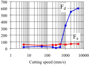
Figure 9 Evolution of the two facial components of the resultant cutting force with the cutting speed (Decès-Petit 1996). (Walnut; nominal thickness =1 mm; clearance angle = 0°)
0 100 200 300 400 500 600 700 1 10 100 1000 10000 Cutting speed (mm/s) Forces (N/cm)
Fa
F
dFigure 10 Lathe check signature (spectrum from knife accelerometer in tangential direction (AXc). The signature (circled) is mainly visible for the higher thickness, only very small lathe check occurring when peeling in 1 mm (grey line). Poplar, without the pressure bar, Vc = 0.5m/s, well honed tool, clearance angle null, thickness of 1 mm: soft-checked veneer / thickness of 3 mm: hard-checked veneer)
Figure 11: Original, preset, and peak detected from the microphone signal for a 3 mm thick beech veneer (Denaud et al 2007 a)
Figure 12 PSD ratio for microphone, AXc and AYc accelerometers (respectively in the tangential and radial direction) between 3 mm. Poplar veneer without pressure bar and reference signal.