ÉCOLE DE TECHNOLOGIE SUPÉRIEURE UNIVERSITÉ DU QUÉBEC
MANUSCRIPT-BASED THESIS PRESENTED TO ÉCOLE DE TECHNOLOGIE SUPÉRIEURE
IN PARTIAL FULFILLMENT OF THE REQUIREMENTS FOR THE DEGREE OF DOCTOR OF PHILOSOPHY
PH.D.
BY
Seyedbehzad GHAFARIZADEH
EXPERIMENTAL INVESTIGATION AND MODELING OF SURFACE MACHINING OF HIGH PERFORMANCE CFRP FOR THE AEROSPACE INDUSTRY
MONTREAL, DECEMBER 21, 2015
This Creative Commons licence allows readers to download this work and share it with others as long as the author is credited. The content of this work may not be modified in any way or used commercially.
BOARD OF EXAMINERS
THIS THESIS HAS BEEN EVALUATED BY THE FOLLOWING BOARD OF EXAMINERS
Prof. Jean-François Chatelain, Thesis Supervisor
Department of Mechanical Engineering at École de Technologie Supérieure
Prof. Gilbert Lebrun, Thesis Co-supervisor
Department of Mechanical Engineering at Université du Québec à Trois-Rivières
Prof. Claudiane Ouellet-Plamondon, Chair, Board of Examiners
Department of Construction Engineering at École de Technologie Supérieure
Prof. Vincent Demers, Member of the jury
Department of Mechanical Engineering at École de Technologie Supérieure
Prof. Marek Balazinski, Member of the jury
Department of Mechanical Engineering at École Polytechnique de Montréal
THIS THESIS WAS PRENSENTED AND DEFENDED
IN THE PRESENCE OF A BOARD OF EXAMINERS AND THE PUBLIC DECEMBER 14, 2015
ACKNOWLEDGMENTS
First of all, I would like to express my sincere gratitude and appreciation for my supervisor professor Jean-Francois Chatelain and my co-supervisor Professor Gilbert Lebrun whose guidance were indispensable for my doctoral research. I am grateful to them for their constant encouragement, guidance and support for my research as well as my professional development.
I would like to acknowledge Prof. Claudiane Ouellet-Plamondon, Prof. Marek Balazinski and Prof. Vincent Demers for serving on my thesis committee. I greatly appreciate for taking the time to critically review this doctoral dissertation.
I sincerely thank Mr. Eric Marcoux at ÉTS machining laboratory, and Mr. Serge St-Martin at Centre Technologique en Aerospatiale (CTA) for their technical assistance related to machining experiments.
I also would like to appreciate the financial support of Consortium for Research and Innovation in Aerospace in Quebec (CRIAQ) and its partners, the Natural Sciences and Engineering Research Council of Canada (NSERC), MITACS, Bombardier Aerospace, Avior Integrated Products, Delastek and AV&R Vision & Robotics.
Last but not least; I would like to thank my parents, Mohammad and Marzieh, for the support they provided me through my entire life. I thank my wife and best friend, Sheida, without whose love, encouragement and editing assistance, I would not have finished this thesis.
ÉTUDE EXPÉRIMENTALE ET MODÉLISATION DE L'USINAGE DE SURFACE DE CFRP HAUTE PERFORMANCE POUR
L'INDUSTRIE AÉRONAUTIQUE
Seyedbehzad GHAFARIZADEH
RÉSUMÉ
Les matériaux composites à fibres de carbone (CFRP) sont largement utilisés dans les structures d'avions en raison de leur faible poids, leur résistance spécifique élevée, leur bonne résistance en fatigue et corrosion ainsi que pour leur flexibilité pour la conception de pièces. Bien que les composantes CFRP soient généralement produites à la forme quasi-finale, l'usinage est souvent nécessaire et pourrait s’avérer plus économique pour éliminer certaines matières excédentaires et amener les pièces à leur taille et forme finales. Cependant, leur usinage est toujours un défi en raison de leur inhérente hétérogénéité et anisotropie, à la source de plusieurs types de dommages, tels que le délaminage, le déchaussement et la fragmentation des fibres. Afin d'améliorer la qualité des pièces produites, une meilleure compréhension de la coupe pendant le processus d’’usinage est nécessaire. Le fraisage de surface est parmi les procédés de parachèvement des composites les moins étudiés pour la finition des pièces. Ainsi, le but de cette étude est de combiner des méthodes numériques et expérimentales afin de réduire les problèmes causés par l’usinage de surfaces de matériaux CFRP et d'acquérir une meilleure compréhension du processus de coupe associé à ce procédé.
Tout d'abord, l’effet des conditions de coupe, telles que la vitesse de coupe, la vitesse d'avance, de même que l'angle d’inclinaison de l’outil, sur les forces et la qualité des surfaces usinées a été étudié. Les résultats expérimentaux ont montré que la meilleure qualité de surface a été produite en utilisant une vitesse d’avance faible, une vitesse de coupe modérée, et un angle d’inclinaison nul de l’axe de l’outil relativement à la surface usinée. Dans la deuxième partie, l’effet des conditions de coupe et de l'orientation des fibres sur la température et les forces engendrées ont été étudiées. Il a été observé que la température de coupe augmentait de manière linéaire avec la vitesse de coupe. Les forces de coupe et températures, maximales et minimales, ont été atteintes pour les orientations des fibres de 90 et de 0 degrés, respectivement.
Finalement, un modèle par éléments finis est proposé afin de prédire les forces de coupe, les mécanismes de formation des copeaux et les dommages d'usinage induits dans un matériau CFRP unidirectionnel. Les résultats de la modélisation ont été validés par des données expérimentales, comprenant entre autres les forces de coupe et des images prises au microscope électronique à balayage (SEM). La comparaison du modèle avec les résultats expérimentaux indique que le modèle proposé est capable de raisonnablement prédire les forces de coupe et les dommages issus de l’usinage. Le modèle développé montre que les dommages d'usinage, la formation des copeaux, et le profil des forces de coupe dépendent fortement de l'orientation des fibres dans le processus de fraisage de surfaces de CFRP.
Mots-clés: usinage de surface, composites à fibres de carbone, plastiques renforcés de
fibres de carbone (CFRP), température de coupe, forces de coupe, rugosité de surface, modélisation par éléments finis
EXPERIMENTAL INVESTIGATION AND MODELING OF SURFACE MACHINING OF HIGH PERFORMANCE CFRP FOR
THE AEROSPACE INDUSTRY
Seyedbehzad GHAFARIZADEH
ABSTRACT
Carbon fiber reinforced plastics (CFRP) have been widely used in many aircraft structures due to their light weight, high specific strength, good resistance to fatigue/corrosion and flexibility in design. Although CFRP components are produced to near-net shape, machining is often needed to remove excess materials and bring the parts to the final size and shape. However, their machining still is a big challenge due to their inherent anisotropy and inhomogeneity, which are the source of several types of damage, such as delamination, fibers pullout, and fiber-fragmentation. In order to improve machining quality and decrease the damages, a better understanding of their machining is required. Surface milling is one of the most practical processes for finishing operations but very few studies have been dedicated to its use for composite components. Thus, the purpose of this study is to use numerical and experimental methods to minimize the machining problems of CFRP materials and to gain a better understanding of CFRP surface milling process.
First, the effects of different cutting conditions such as cutting speed, feed rate, and lead angle on cutting forces and surface quality were studied and the optimum cutting condition was determined. The experimental results showed that the best surface quality was achieved by using lower cutting feed rate, moderate cutting speeds, and zero degree tool lead angle. In the second part, the effects of cutting conditions and fiber orientation on cutting temperature were investigated. It was found that the cutting temperature increases linearly with the cutting speed. The maximum and minimum cutting forces and temperatures were achieved for fiber orientations of 90 and 0 degrees, respectively.
Then, a finite element model was developed to predict cutting forces, chip formation mechanism and machining damages obtained during milling of unidirectional CFRP. The modeling results were validated by experimental data, including cutting forces and SEM images. A comparison of modeling and experimental results indicated that the proposed model is able to successfully predict the cutting forces and machining damages. The developed model showed that the machining damages, the chip formation, and the cutting force profile strongly depend on fiber orientation in CFRP milling process.
Keywords: Surface machining, carbon fiber reinforced plastics (CFRP), cutting
TABLE OF CONTENTS
Page
INTRODUCTION ...1
CHAPTER 1 CHALLENGE DESCRIPTION, OBJECTIVES AND ORIGINAL CONTRIBUTIONS ...5
1.1 Challenge description...5
1.2 Research objectives ...6
1.3 Original contributions ...6
CHAPTER 2 LITERATURE REVIEW ...9
2.1 Carbon fiber reinforced plastics ...9
2.2 Surface milling of CFRP ...9
2.2.1 Milling Geometry ... 10
2.2.2 Chip formation mechanism ... 11
2.2.3 Cutting forces in CFRP machining ... 12
2.2.4 Machining Induced Damage and Surface Integrity ... 14
2.2.5 Cutting temperature in CFRP milling ... 17
2.3 Finite element modeling of CFRP machining ...18
2.3.1 Finite element formulations ... 19
2.3.2 Definition of CFRP material in finite element method (FEM) ... 20
2.3.3 Friction at the tool/workpiece interface ... 21
2.3.4 Failure criteria and chip formation ... 22
2.4 Summary ...25
CHAPTER 3 EFFECT OF CUTTING TOOL LEAD ANGLE ON MACHINING FORCES AND SURFACE FINISH OF CFRP LAMINATES ...27
3.1 Abstract ...27
3.2 Introduction ...28
3.3 Materials and methods ...31
3.4 Results ...34
3.4.1 Effects of feed rate and cutting speed on surface roughness ... 34
3.4.2 Effects of feed rate and cutting speed on cutting force ... 37
3.4.3 Effects of lead angle on surface roughness and cutting force ... 39
3.5 Conclusions ...40
3.6 Acknowledgment ...42
3.7 References ...42
CHAPTER 4 EXPERIMENTAL INVESTIGATION OF THE CUTTING TEMPERATURE AND SURFACE QUALITY DURING MILLING OF UNIDIRECTIONAL CFRP ...45
4.1 Abstract ...45
4.3 Methodology ... 49
4.4 Results and discussion ... 53
4.4.1 Effects of cutting speed on the cutting force and cutting temperature ... 53
4.4.2 Effects of fibers orientation on the cutting temperature and cutting force ... 57
4.4.3 Effects of fibers orientation and cutting speed on surface quality ... 58
4.5 Conclusion ... 64
4.6 Acknowledgments ... 65
4.7 References ... 65
CHAPTER 5 FINITE ELEMENT ANALYSIS OF SURFACE MACHINING OF CARBON FIBER REINFORCED COMPOSITES ... 69
5.1 Abstract ... 69 5.2 Introduction ... 70 5.3 Experimental procedure ... 72 5.3.1 Composite Materials ... 72 5.3.2 Milling process ... 74 5.4 Numerical modeling ... 74
5.4.1 Geometry, contact, meshing and analysis ... 74
5.4.2 Contact modeling ... 77
5.4.3 Failure criteria ... 77
5.5 Results and discussion ... 79
5.5.1 Chip formation ... 79 5.5.2 Cutting forces ... 81 5.5.3 Surface integrity ... 82 5.6 Conclusion ... 84 5.7 Acknowledgments ... 85 5.8 References ... 85 CONCLUSIONS 89 RECOMMENDATIONS ... 91 LIST OF REFERENCES ... 101
LIST OF TABLES
Page Table 3-1 Description of tool geometries ...32 Table 3-2 Cutting parameters ...33 Table 3-3 Values of resultant cutting force (Fc) and surface roughness (Ra) as a
function of the cutting parameters (average of three times repetition) ...35 Table 4-1 Mechanical and physical properties of CFRP (reported by supplier) ...49 Table 4-2 Cutting conditions ...53 Table 5-1 Mechanical and physical properties of CFRP unidirectional laminate
LIST OF FIGURES
Page Figure 0-1 The application of composite materials in different parts of the
Bombardier CSeries (Kafyeke, 2010). ...1
Figure 2-1 a) Unidirectional lamina, b) woven fibers c) laminate (Campbell, 2010; Daniel et Ishai, 2006) ...9
Figure 2-2 a) face milling, b) milling geometry (Sheikh-Ahmad, 2008) ...10
Figure 2-3 Cutting mechanisms in different fiber orientations (Sheikh-Ahmad, 2008). .11 Figure 2-4 Variation of cutting and thrust forces per unit width with fiber orientation, 1-Carbon F593/epoxy, 2- Carbon (Torayca T300), 3-Graphite IM6/epoxy, 4-Carbon T300/epoxy (Sheikh-Ahmad, 2008). ...13
Figure 2-5 Variation of the cutting force with different cutting speeds and feed rates in machining CFRP with PCD tool(Sheikh-Ahmad, 2008). ...15
Figure 2-6 Surface characters, lay, waviness, and roughness (Sheikh-Ahmad, 2008) ...15
Figure 2-7 Damage at different fiber orientations; (a-b) 45°; (c-d) 0°; (e-f) 90°; (g-h) 135° (El-Hofy et al., 2011). ...16
Figure 2-8 One dimensional example of Eulerian, Lagrangian and arbitrary lagrangian eulerian (ALE) mesh (Stein, de Borst et Hughes, 2004) ...19
Figure 2-9 Failure modes in machining of CFRP (Kollár et Springer, 2003). ...22
Figure 2-10 Measured and predicted values of a) cutting force Fc ,and b) thrust force Ft (γ = 10˚ and ap = 0.2mm) (Mkaddem, Demirci et Mansori, 2008). ...24
Figure 2-11 Comparison between experimental and predicted values of cutting force using Hashin, Maximum stress, and Hoffman failure criteria, (a) Principal cutting force, (b) Thrust cutting force ...25
Figure 3-1 Experimental setup for machining of CFRP ...30
Figure 3-2 The layup of multidirectional CFRP ...31
Figure 3-3 Two-flute polycrystalline diamond (PCD) ball end mills ...32
Figure 3-5 Effects of feed rate and cutting speed on the Ra, 0º lead angle. ... 36
Figure 3-6 Effect of feed rate and cutting speed on the Rt, 0º lead angle. ... 36
Figure 3-7 Effects of feed rate and cutting speed on the cutting force, 0º lead angle ... 37
Figure 3-8 Effect of cutting speed on the quality of machined surface, lead angle 0º , a) Cutting speed 250 m/min, feed rate 0.063 mm/rev, b) Cutting speed : 375 m/min, feed rate=0.254 mm/rev ... 38
Figure 3-9 Effect of lead angle on the roughness Ra for different cutting speeds (feed=0.0635 mm/rev) ... 39
Figure 3-10 Effect of lead angle on the cutting force, Cutting speed: 250 m/min (feed= 0.063 mm/rev) ... 40
Figure 3-11 SEM images of machined surface with different lead angles (cutting speed 250 m/min, feed rate 0.063 mm/rev) ... 41
Figure 4-1 CFRP milling setup ... 50
Figure 4-2 The schematic of the milling process geometry ... 51
Figure 4-3 Cutting tool ... 51
Figure 4-4 Measuring of cutting temperature and cutting force ... 52
Figure 4-5 Fiber orientation angle in milling experiments ... 52
Figure 4-6 Measuring of surface roughness using contact profilometer ... 54
Figure 4-7 Effect of cutting speed on the maximum cutting temperature for different fiber orientations ... 55
Figure 4-8 Effect of cutting speed on the maximum resultant cutting force for different fiber orientations ... 56
Figure 4-9 Effect of fiber orientation on the maximum resultant cutting force for different cutting speeds ... 57
Figure 4-10 Effect of fiber orientation on the maximum cutting temperature at different cutting speeds ... 58
Figure 4-11 Effects of fiber orientation and cutting speed on surface roughness (standard deviations (σ) of 0.06 to 0.33 µm) ... 59
Figure 4-12 Surface damages at different cutting speeds and Fiber orientation angle: Fiber fracture (F.F), fiber pullout (F.P), fiber/Matrix de-cohesion (F.D),
loss of fibers (L.F). ...60
Figure 4-13 Cutting forces for different cutting speeds and fiber orientations. ...62
Figure 4-14 Cutting forces in time domain a) Fiber orientation angle 0° and cutting speed 200 m/min), b) fiber orientation angle 45° and cutting speed 250 m/min ...63
Figure 4-15 3D topography of surfaces machined with confocal laser microscope a) cutting speed 200 m/min and fiber orientation 0°, b) cutting speed 300 m/min and fiber orientation 45°, c) cutting speed 375 m/min and fiber orientation 45°, d) cutting speed 375 m/min and fiber orientation 90° ...63
Figure 5-1 Milling experiments set-up ...73
Figure 5-2 Cutting tool geometry ...73
Figure 5-3 Numerical modeling set-up ...75
Figure 5-4 Variation of coefficient of friction with respect to fiber orientation (Mkaddem et El Mansori, 2009; Nayak, Bhatnagar et Mahajan, 2005) ...78
Figure 5-5 Chip formation mechanism in milling of CFRP with a 0° feed rate orientation ...80
Figure 5-6 Comparison between experimental and simulated values of the cutting forces for a 0° machining direction, a 250 m/min cutting speed, a 0.063 mm/rev feed rate and a 0.5 mm depth of cut ...82
Figure 5-7 Comparison between experimental and simulated values of the cutting forces with 90° machining direction, 250 m/min cutting speed, 0.063 mm/rev feed rate, 0.5 mm depth of cut ...82
Figure 5-8 CFRP machined surface for different machining directions of 0 (a), 90 (b), 45 (c) and 135 (d) degrees, 250 m/min cutting speed, 0.063 mm/rev feed rate, 0.5 mm depth of cut ...83
Figure 5-9 Machining damage at different tool rotation angles: fiber pullout (FP), fiber/matrix de-cohesion (F.D), Matrix Cracking (MC), magnification. ...83
LIST OF ABREVIATIONS
CFRP Carbon fiber reinforced plastic
GFRP Glass fiber reinforced plastic
ALE Arbitrary Lagrangian-Eulerian
EHM Equivalent homogeneous material
PCD Polycrystalline diamond
WC Tungsten carbide
FEM Finite element method
SEM Scanning electron microscopy
2D Two dimensional
LIST OF SYMBOLS AND UNITS OF MEASUREMENTS
Symbol Unit Description
vC m/min Cutting speed
af mm Feed per tooth
N rev/min Spindle speed
vf mm/min Feed rate
z - Number of edges
D mm Cutter diameter
ap mm Axial depth of cut
ae mm Radial depth of cut
Ra µm Arithmetic mean value of the roughness
Rt µm Roughness - maximum peak to valley height
Rp µm Roughness- maximum peak to mean height
Rv µm Roughness - mean to valley height
Rz µm Roughness - ten point average height
Sa µm Arithmetic average of the 3D roughness
St µm Maximum profile height of the 3D roughness
Bij - In-plane/flexure coupling stiffnesses
Ais - In-plane shear coupling stiffnesses
Dis - Bending/twisting coupling stiffnesses
fn kHz Natural frequency
Fc N Resultant cutting force
Vf % Fiber volume content
Wf % Fiber weight content
θc °C Cutting temperature
µ - Friction coefficient
Tg °C Glass transition temperature
E1 GPa Longitudinal modulus
E2 GPa Transverse modulus
ν12 Major Poisson’s ratio
XT MPa Longitudinal tensile strength
XC MPa Longitudinal compressive strength
YT MPa Transverse tensile strength
YC MPa Transverse compressive strength
SL MPa Longitudinal shear strength
ST MPa Transverse shear strength
KJ/m2 Fracture energy - fiber tension KJ/m2 Fracture energy - fiber compression KJ/m2 Fracture energy - matrix cracking KJ/m2 Fracture energy - matrix crushing
ρ g/cm3 Specific gravity
τn MPa Frictional stress
σn MPa Normal stress
σ11 MPa Normal stresses in fiber direction
σ22 MPa Normal stresses in transverse direction
INTRODUCTION
Carbon fiber reinforced plastics (CFRPs) are an important class of composite materials that are widely used in many industrial sectors such as aerospace, construction, and transportation. CFRPs are increasingly used for different aircraft parts, such as wing boxes, fuselage, ailerons, wings, spoilers, vertical stabilizers, cowlings, traps and struts (Daniel et Ishai, 2006; Girot et al., 2009). This group of composite materials have various advantages such as high strength and stiffness properties, long fatigue lifespan, low density, and high corrosion/wear resistance. Because carbon fibers have a negative coefficient of thermal expansion along their axis, CFRPs have very low in-plane expansions over a wide range of temperatures, and this is very important for aerospace structures (Sheikh-Ahmad, 2008). The first composite aircraft component was made in 1968 and since then, tendency for using composite materials in aerospace industry was unceasingly increased since late of 1970s (Daniel et Ishai, 2006). Currently, 52% of the weight of Airbus A350, 50% of the weight of the Boeing 787, and 46% of the weight of the Bombardier CSeries are made of composite materials such as CFRPs. As shown in (Figure 1-1), advanced composite materials (46% of the weight) including CFRPs are utilized in wings, torque box and wing skins in Bombardier CSeries (Marsh, 2011).
Figure 1-1 The application of composite materials in different parts of the Bombardier CSeries (Kafyeke, 2010)
CFRP parts are usually produced in near net-shape but machining operations are often required to remove excess of materials, to bring the parts to their final size and shape, and to produce high quality surfaces. The machining of CFRP has many challenges due to their heterogeneous and anisotropic nature causing some damages such as delamination, fiber pull out, fiber-fragmentation, burring, and fuzzing. These damages decrease the properties and performances of manufactured components and could cause catastrophic incidents and significant costs in aerospace industries. Therefore, the prediction, evaluation and study of those damages are vital to prevent such disasters. Although there are many researches that have been carried out on drilling and trimming of CFRP materials, there are few researches regarding surface machining of these materials. Hence, a comprehensive study of the surface machining of CFRP process is necessary.
Making use of the developments in computer related technologies, many researchers have attempted to use different modeling methods to study the milling process of CFRPs. Previous researches have focused their efforts on the use of artificial neural networks (Kalla, Sheikh-Ahmad et Twomey, 2010) and empirical methods (Karpat, Bahtiyar et Değer, 2012; Zaghbani et al., 2012a). However, these models are not able to predict the mechanism of chip formation and the underlying machining damages. The numerical modeling of CRFP milling process taking into account the chip formation is thus required to understand the machining quality and cutting mechanisms.
In this research, the effects of different cutting conditions including the feed rate, cutting speed, tool lead angle, and fiber orientation on surface quality, cutting force and cutting temperature have been studied. In addition, a finite element model has been developed to study the cutting forces, chip formation and machining damages during CFRP milling. This research manuscript is divided into 7 chapters. In the first chapter, challenges description, objectives and the original contributions of this study are described. The second chapter gives a brief description of basic knowledge about CFRP materials. It also presents a short overview of milling process for composites and the previous experimental and modeling researches made on the milling of CFRP materials.
The third chapter is the first published journal paper. This paper presents an experimental research to study the optimum cutting conditions for multiaxis ball-end milling of multidirectional CFRP materials. It investigates the effects of different cutting conditions such as feed rate, cutting speed and tool lead angle on surface roughness and cutting forces. The findings of this chapter regarding the optimized cutting conditions (cutting speed, feed rate and lead angle) have been used in the next chapters.
The fourth chapter presents the second published journal paper. This chapter focuses on thermal aspects of CFRP milling. Milling experiments have been carried out on a unidirectional carbon fiber reinforced plastic to investigate the effects of fibers orientation and cutting speed on the cutting temperature, cutting force and surface damages. The ball-end milling tests were performed under the optimum cutting conditions found in the third chapter (moderate cutting speeds, low feed rate and zero degree lead angle).
Chapter five presents the third journal paper regarding the simulation of the CFRP milling process. According to the findings of chapters 3 and 4 for the ball-end milling, the best surface quality was achieved with a 0° tool lead angle. Based on this result, a new flat-end mill was selected and more experiments were carried out in 0° tool lead angle. Then, a combined micro-macro mechanical model has been developed to study the cutting forces, chip formation and machining damages during CFRP flat-end milling. The proposed model took the advantages of both macro (modeling the composite as an equivalent homogeneous material) and micro scales (use of adaptive meshing and related friction coefficient to fibers orientation) approaches to predict the cutting forces with good agreement to the experiments. Finally, the last two chapters present the conclusions and recommendations that resulted from this study.
CHAPTER 1
CHALLENGE DESCRIPTION, OBJECTIVES AND ORIGINAL CONTRIBUTIONS 1.1 Challenge description
Applications of CFRP in aerospace industry is rapidly increasing due to their special properties such as high strength, high stiffness, long fatigue life, low density, good corrosion resistance and wear resistance. In spite of having these advantages, CFRP machining is still a big challenge due to their inhomogeneous and anisotropic nature that result in machining problems such as delamination, fibers pullout, fiber-fragmentation, burring, and fuzzing. Occurrence of these defects even in a small extent may cause catastrophic incidents in aerospace applications where parts are undergoing cyclic and dynamic loadings. Furthermore, tool wear is one of the major problems in CFRP machining due to extremely abrasive characteristics. Poor cutting conditions can accelerate tool wear rate and as a result increase the machining costs. To achieve the high quality of machined surfaces, it is necessary to understand the cutting mechanism and investigate the effects of different machining parameters.
In addition to aforementioned challenges during machining, the experimental study of composite machining is time consuming and is an expensive process with some dangers to human health due to the production of carbon chips and dusts during the operation. Moreover, the interpretation of the experimental results of milling is difficult due to complexity of the process. Therefore, the finite element modeling of CFRP machining could be a good alternative method to study and investigate the machining process of CFRP composites including chip formation, cutting forces, and surface machining damages. Recently, with the improvement in computer technology and equipment, many researchers have focused on modeling of CFRP machining. But in spite of existing many proposed models for simulating CFRP orthogonal cutting, there is no numerical models for simulating the CFRP surface machining process such as milling process.
1.2 Research objectives
In order to promote the use of composite materials in aerospace industries, it is critical to overcome their machining limitations. Therefore, the main purpose of this research is to improve machining quality of CFRP materials and to provide a better understanding of their milling process. Cutting forces are among the important machining factors that influence the process stability, machining quality, cutting temperature, and tool conditions.
Hence, the objectives of this research are to investigate the effects of machining conditions such as cutting speeds, feed rate, and tool lead angle on cutting forces and surface quality, and to optimize the cutting conditions for surface milling of CFRP. Since cutting temperature is an influent factor on machining quality and tool wear, the other purpose of this work is to focus on the thermal aspects of CFRP milling process. Therefore, the effects of cutting parameters such as the cutting speed and fiber orientation on the cutting temperature and surface damage were studied. Another objective of this work is to develop a finite element model to analyse the CFRP milling process and predict the cutting forces, chip formation and machining damages.
1.3 Original contributions
The CFRP surface milling process is investigated in this research work using the experimental and modeling methods. The original contributions of this work can be summarized in the following main points:
• The effects of tool lead angle (the angle between the tool axis and the surface normal) on cutting force, surface roughness, and machining damages was studied during the surface milling of CFRP materials.
• The effects of the cutting conditions such as cutting speed and fiber orientation on the cutting temperature were investigated during the CFRP ball end milling process. Based on the experimental results, the influences of the cutting temperature on cutting force and machining quality were studied to provide a better knowledge of thermal aspect of CFRP milling and improve the machining quality.
• The first finite element model was developed to study flat-end milling of CFRP material. The composite material was modeled as an equivalent homogeneous material and the friction coefficient between the tool and workpiece was assumed dependent to fibers orientation. The model was able to predict cutting forces, chip formation mechanism and machining damages in good agreement with the experiments. The presented finite element mode was applied to study the effect of fiber orientation and machining direction on the cutting forces.
CHAPTER 2
LITERATURE REVIEW 2.1 Carbon fiber reinforced plastics
Carbon fiber reinforced plastics (CFRPs) are used widely in aerospace industries, due to their advantages such as high tensile and compressive strength, and high fatigue and corrosion resistances. However, CFRPs are expensive and difficult to machine compared to metals (Daniel et Ishai, 2006; Gudimani, 2011; Teti, 2002). As shown in Figure 2-1, the carbon fiber in CFRPs can be unidirectional (unidirectional lamina or ply) or woven. To obtain quasi-isotropic properties, the individual lamina can be stacked with various orientations with respect to laminate global coordinate system (Daniel et Ishai, 2006).
Figure 2-1 a) Unidirectional lamina, b) woven fibers c) laminate (Campbell, 2010; Daniel et Ishai, 2006)
2.2 Surface milling of CFRP
Milling processes are usually required to remove the excess of material and bring the parts to their final size and shape. In the milling operation, cutting is performed by a rotating multi-teeth cutter and often more than one cutting edge are cutting at the same time. Thus, the milling process is complex due to the variation of fiber orientation, chip size and cutting forces with tool rotation. The different aspects of CFRP surface milling process, including
milling geometry, chip formation, cutting forces and the quality of machined surfaces, are studied in section 2.2.
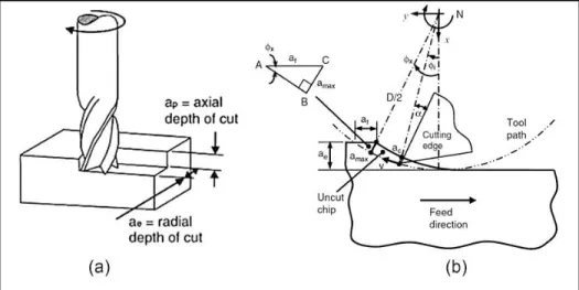
2.2.1 Milling Geometry
Figure 2-2 shows the face (end) milling process and the cutting geometry in end milling. Different parameters of milling are shown in this picture. The spindle speed shown by letter N in the Figure 2-2b is the number of revolutions of the milling tool per minute.
Figure 2-2 a) face milling, b) milling geometry (Sheikh-Ahmad, 2008)
Cutting speed (νC) is an important parameter indicating the speed at which the cutting
edge machines the workpiece and is defined by the following equation:
= × ×
1000 ( ⁄ )
(1-1)
Where D and N represent the tool diameter and spindle speed, respectively. Feed speed (νf) is the feed of the tool against the workpiece, in units of distance per time and feed per
revolution (f) is a value used to determine finishing capacity. These two parameters are related by the following equation:
=
Milling tools are multi-edge cutters, and the feed per tooth (af9), as a value for ensuring
that each edge machines under satisfactory condition, is defined with the following equation:
=
× ( / ℎ) (1-3)
Where, z is number of edges of the tool.
2.2.2 Chip formation mechanism
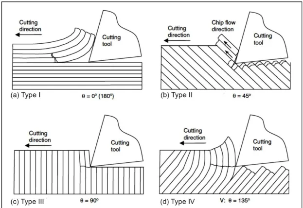
The chip formation mechanism in CFRP milling is controlled by the fibers orientation. The fibers orientation varies continuously with tool rotation during milling process. Thus, different cutting mechanisms are responsible for chip formation process during mill rotation.
Figure 2-3 shows four types of chip formation mechanisms for different fiber orientations with respect to the cutting direction (Sheikh-Ahmad, 2008).
For fibers oriented at 0° (Figure 2-3a), a crack initiates at the contact point of the workpiece and tool; and it propagates along the fiber-matrix interface. When the tool advances into the workpiece, the peeled layers bend and compress in the opposite direction to fibers. The fiber-matrix debonding continues until the bending stress in the fibers increases up to failure stress, and fiber failure occurs ahead of the cutting tool. The chip formation mode in 0° fibers orientation is of delamination type.
The second type of chip formation is fiber cutting (with continuous chip), that occurs for fiber orientations between 0° and 90° (Figure 2-3b). The chip formation mechanism consists of fracture from compression-induced shear perpendicular to fiber axis followed by shear fracture along the fiber–matrix interface occurring with the cutting edge movement. The cracks generated in the fibers above and below the cutting plane during the compression stage of the chip formation remain after machining and cause low quality machined surfaces.
For fibers at 90° (Figure2-3 c), fibers crush and fail at the contact point of the tool and the workpiece and each fiber is cut separately. The chip formation mechanism in this case is called fiber cutting type (with discontinuous chip).
For large fiber orientation angles (105–150°) where the tool enters the workpiece and catches on a peeled fiber, the fiber-matrix interfacial failure occurs below the cutting plane (Figure 2-3d). Fiber failure below the cutting plane occurs when the bending stresses that develop in the fibers below the surface of the cut are large enough for fracture. In this type of chip formation (type V- macrofracture) discontinuous chips are formed. A poor surface quality results from this orientation because of extensive fiber pull-out and delamination cracking (Sheikh-Ahmad, 2008; Teti, 2002)
2.2.3 Cutting forces in CFRP machining
Cutting forces are one of the important factors influencing the process stability, part quality, cutting temperature, and the tool conditions. A number of studies have been carried out about cutting forces and the effect of parameters such as fiber orientation, cutting speed and tool geometry on them. These studies show large fluctuations in the cutting forces during
machining of fiber reinforced polymers. Cutting and thrust forces are strongly dependent on fiber orientation, while the operating conditions and the tool geometry will also have influence on them. Figure 2-4 shows typical cutting force evolutions during trimming (edge milling) of CFRP and GFRP (Glass fiber reinforced plastic) with different cutting conditions (Sheikh-Ahmad, 2008).
Figure 2-4 Variation of cutting and thrust forces per unit width with fiber orientation, 1-Carbon F593/epoxy, 2- Carbon (Torayca T300), 3-Graphite IM6/epoxy, 4-Carbon
T300/epoxy (Sheikh-Ahmad, 2008)
As can be seen in Figure 2-4, generally the cutting force remains almost constant up to fiber orientations of approximately 60°, then it rapidly increases with fiber orientations up to 90°. Then the cutting force decreases with more increase in fiber orientation with a significant decrease occurring between 100° and 165° (Sheikh-Ahmad, 2008). The results of other studies on orthogonal cutting of FRP materials also showed that cutting and trust forces are highly dependent on fiber orientation (Dandekar et Shin, 2008; Gao et al., 2015; Ramulu, 1997; Rao, Mahajan et Bhatnagar, 2008; Rao, Mahajan et Bhatnagar, 2007b; Santiuste et al., 2014; Santiuste, Soldani et Miguélez, 2010; Wang, Ramulu et Arola, 1995; Zenia et al., 2015).
Fiber orientation is the most important factor influencing the cutting forces, but tool geometry, tool rake (the angle between the cutting face of the tool and a line perpendicular to the work piece), clearance angle (the angle between the flank face of the tool and the workpiece) and cutting parameters such as depth of cut and material removal rate also have effects on cutting forces. Cutting and thrust forces are decreased by increasing the rake angle; however the effect of rake angle is not as significant as fiber orientation and depth of cut (Wang et Zhang, 2003). Generally, cutting and thrust forces are decreased by increasing the clearance angle (Calzada et al., 2012).
Chatelain et al. investigated the effects of tool geometry on cutting forces in trimming of CFRP. The results of their studies showed that tool geometry (number of flute, helix and rake angle) has a significant effect on cutting forces (Chatelain et Zaghbani, 2011). In another study, Zaghbani et al. (Zaghbani et al., 2012b) showed that the force amplitude is dictated by the tool geometry, the type of machining operation, and material properties (the fiber orientation) in milling of CFRP. They also concluded that the cutting force profile does not significantly depend on fibers orientation. Karpat et al. (Karpat, Bahtiyar et Değer, 2012) presented a mechanistic cutting force model for milling CFRPs. In contrast to the finding of Zaghbani et al., they showed that fiber orientation significantly affects the cutting force profile and amplitude.
Cutting parameters such as cutting speed, depth of cut, and feed rate are other factors influencing the cutting forces. Generally, cutting forces are increased by the material removal rate. Therefore, thrust and cutting forces rise with increasing the feed rate and depth of cut during machining of CFRP (Rusinek, 2010). Experimental studies showed that the variation of cutting forces is not uniform over the variation of cutting speeds. As shown in Figure 2-5, moderate cutting speeds (between 200-300 m/min) were more suited for the machining of CFRPs.
2.2.4 Machining Induced Damage and Surface Integrity
Several aspects including subsurface damage and surface roughness are considered to characterize the results of surface machining process such as milling and trimming. The
surface profile is typically described by its lay (the main direction of the surface texture), waviness, and roughness. The conceptual opposite from smoothness of a technical surface is designated as roughness. Waviness is the characteristic form of topographical variations that are measurable on the part profile in an actual or imaginary cross section (Figure 2-6a).
Figure 2-5 Variation of the cutting force with different cutting speeds and feed rates in machining CFRP with
PCD tool(Sheikh-Ahmad, 2008)
Lay is the macroscopic contour of the surface and describes the direction of the predominant surface pattern. The surface waviness, profile and surface roughness parameters (arithmetic mean value Ra, maximum peak to valley height Rt, maximum peak to mean height Rp, mean to valley height Rv, and ten point average height Rz) are shown in Figure 2-6b
(Farago et Curtis, 1994).
Figure 2-6 Surface characters, lay, waviness, and roughness (Sheikh-Ahmad, 2008)
The roughness of a machined surface is affected by machining parameters (feed rate, cutting speed, and depth of cut), tool geometry, tool wear, and fiber orientation. Generally, the value of Ra and Rz increases by increasing the feed rate and decreases by increasing the
cutting speed. However, the effect of cutting speed is not as significant as feed rate (Chatelain, Zaghbani et Monier, 2011; Chatelain, Zaghbani et Monier, 2012; Davim et Reis, 2005; Davim, Reis et António, 2004). Wang and Zhang found that a smaller depth of cut generates less sub surface damages (Wang et Zhang, 2003).
El-Hofy et al. (El-Hofy et al., 2011) investigated the effects of different slotting parameters such as tool materials (WC & PCD) and cutting environment (chilled air and dry) on the surface roughness and integrity using 3D roughness parameters (Sa and St). According
to their results, the combination of low cutting speed and high feed rate was recommended for an improved surface roughness. By using analysis of variance (ANOVA), they showed that tool material was not a statistically significant factor; with a relatively low PCR of 5.44%. They also studied the effects of fiber orientation on surface roughness. The fibers fractured by buckling were removed cleanly, with the least surface damage, for a fiber orientation of 0°. Wavy surfaces were observed for plies oriented at 45° while those at 90° and 135° suffered matrix cracking and fiber pull out due to the high cutting forces and softening of the resin (Figure 2-7).
Figure 2-7 Damage at different fiber orientations; (a-b) 45°; (c-d) 0°; (e-f) 90°; (g-h) 135° (El-Hofy et al., 2011)
Sheikh-Ahmad et al. (Sheikh-Ahmad, Urban et Cheraghi, 2012) carried out an experimental study to determine the effects of cutting conditions on machining quality during edge trimming of CFRP. They demonstrated that the surface roughness and average delamination depth increase with an increase in feed rate and decrease with an increase in spindle speed. Feed rate had the highest influence on the surface roughness and delamination followed by cutting distance and cutting speed.
Machined CFRPs have roughness and subsurface damages that are influenced by fiber orientation. Ramulu (Ramulu, 1997) studied the effect of fibers orientation on surface quality and concluded, by measuring the average surface roughness in both longitudinal and transverse directions, that for fiber orientations between 15 to 60° good surface qualities can be obtained. He deduced that for an orientation of 135°, extensive fiber pull-out and delamination cracking occurred. Therefore, poor surface quality was obtained for this orientation. A recent study that has been carried out by Chatelain et al. (Chatelain, Zaghbani et Monier, 2012) confirmed the results of Ramulu’s work. They showed that all roughness parameters (Ra, Rp, Rq, Rv, and Rz) were worse at 135° than for other orientations. The best
surface quality was obtained for fibers at 45°.
The cutting of CFRPs is difficult due to diverse fiber and matrix properties, inhomogeneous nature of the material, and the presence of a high volume fraction of hard abrasive fibers in the matrix. They are especially vulnerable to the generation of damages such as delamination, fiber pull-out and matrix thermal degradation during machining. Davim et al. (Davim et Reis, 2005) investigated the influence of cutting parameters (cutting velocity and feed rate) and tool geometry on delamination. They showed that delamination increases with increasing feed rate and cutting speed. They also found that a two flute end mill presents less delamination compared to a six flute end mill.
2.2.5 Cutting temperature in CFRP milling
The cutting temperature is an important factor in the machining of composite materials that influences the quality of the machined surface and tool wear. However, only a few papers have covered the effect of cutting temperature in the surface milling of CFRP.
Yashiro et al. (Yashiro, Ogawa et Sasahara, 2013) studied the cutting temperature in CFRP milling. They found that the tool-workpiece contact point temperature increased up to 180 °C (the glass transition temperature) when the cutting speed reached 25 m/min, and up to 300 °C for a cutting speed of 50 m/min. The cutting temperature tends to stabilize and remain constant when the cutting speed was increased further.
In a recent research, Liu et al. (Liu et al., 2014) developed a mathematical model to predict the spatial and temporal distribution of the temperature in helical milling of CFRP. They concluded that the workpiece temperature increases with the spindle speed and axial depth of cut. The axial cutting depth had more influence than spindle speed on temperature variation of the workpiece, while the influence of tangential feed per tooth was less than the other factors.
2.3 Finite element modeling of CFRP machining
Recently, many researchers have focused on investigation of CFRP machining using modeling to decrease the experiments, which are time consuming and expensive. But in the literature, very few works attempt to model the cutting forces in surface milling of fiber reinforced composites. Generally, the modeling methods of FRP machining can be classified in two general approaches: (I) theoretical and empirical models and (II) numerical models. Theoretical and empirical models were used to study the FRP milling process (Karpat, Bahtiyar et Değer, 2012; Zaghbani et al., 2012a), but using these models is very complicated because of the highly nonlinear and inhomogeneous nature of composite materials. Another problem is the lack of cutting force coefficients that are necessary for these modeling techniques, especially for modelling oblique cutting for different tool/workpiece combinations (Calzada, 2010; Kalla, Sheikh-Ahmad et Twomey, 2010). In addition, these models are not able to predict machining damages and cutting mechanism.
More recently, with the improvement in computer technology, many researchers have focused on studying composite machining by numerical methods such as finite element modeling. Finite element models are able to predict the cutting forces, chip formation mechanisms, and material damage in the machining of a complex multi-phase and
anisotropic material (Calzada, 2010). In spite of existing many models for simulating CFRP orthogonal cutting, there is no finite element model for simulating the complicated surface machining process of CFRP such as the surface milling process.
2.3.1 Finite element formulations
For machining simulations using finite element modeling, three formulations have been used: Eulerian, Lagrangian, and Arbitrary lagrangian eulerian (ALE) (Figure 2-8).
Figure 2-8 One dimensional example of Eulerian, Lagrangian and arbitrary lagrangian eulerian (ALE) mesh
In the Eulerian method, the mesh is spatially fixed in order to eliminate excessive element distortion, but material can flow through a meshed control volume. In this method, cutting is simulated in the steady state and therefore there is no need for chip separation criteria. The disadvantage of this method is that the initial shape of the chip and the contact conditions must be known.
In Lagrangian method, the mesh is attached to the workpiece and the elements can deform similarly to actual machining. Knowing the chip geometry is not necessary using this formulation. Lagrangian mesh always contains the same material particles. From a computational viewpoint, it is one of significant advantages of this method, especially in problems involving materials with history-dependent behaviors. The disadvantages of this method are the excessive element distortion that reduces the accuracy in large material deformation and the need for frequent remeshing.
In order to have the advantages of both Eulerian and Lagrangian approaches, the arbitrary lagrangian eulerian (ALE) method was developed. In this method, the finite element mesh is neither fixed nor attached to the workpiece material (Stein, de Borst et Hughes, 2004).
2.3.2 Definition of CFRP material in finite element method (FEM)
The numerical modeling of fiber reinforced composites can be classified in two general approaches: (I) micromechanical approach where the composite is modeled as multi-phase material and (II) macro mechanical approach where the composite is modeled as an equivalent homogeneous material (EHM).
The micromechanical approach was used successfully to predict cutting forces and local defects in orthogonal cutting of FRP (such as debonding) (Calzada et al., 2012; Dandekar et Shin, 2008; Nayak, Bhatnagar et Mahajan, 2005; Rao, Mahajan et Bhatnagar, 2007a; Rao, Mahajan et Bhatnagar, 2007b). Despite the advantages of the micromechanical approach, such as good accuracy of predicted cutting force and damages, it has some limitations. The micro modeling is more complex than macro modeling and needs very high calculation time
and precise details of fibers, fiber-matrix arrangements and their interfacial and physical properties (Dandekar et Shin, 2012). Because of these limitations, the macro mechanical modeling is preferable for modeling complex processes such as milling.
The first macro-mechanical FEM analysis of fiber-reinforced composites was developed by Arola and Ramulu (Arola et Ramulu, 1997) in 1995. The predicted values of principal cutting force agreed well with the experimental values but the predicted thrust force was much lower than experiments. The results of other studies also confirm the shortcoming of macromechanical modeling to predict the thrust forces (Arola, Sultan et Ramulu, 2002; Lasri, Nouari et El Mansori, 2009; Nayak, Bhatnagar et Mahajan, 2005; Santiuste, Soldani et Miguélez, 2010). Mkaddem et al. (Mkaddem et El Mansori, 2009; Mkaddem, Demirci et Mansori, 2008) developed a micro-macro model to get the advantages of both approaches. The composite was modeled as a homogeneous material with anisotropic effective friction coefficients. The model incorporates the adaptive mesh technique and density effect to analyse composite machining. It successfully predicted the sub-surface damages, cutting and thrust forces with lower mean errors (6% for cutting forces and 26% for thrust forces) than another macromechanical model presented by Nayak et al. (17% for cutting forces 44% for thrust forces) (Nayak, Bhatnagar et Mahajan, 2005).
2.3.3 Friction at the tool/workpiece interface
Friction is another important parameter in machining simulation. An accurate modeling of the coefficient of friction allows for accurate prediction of cutting forces and temperature distributions. Mahdi and Zhang (Mahdi et Zhang, 2001a) assumed that tool-workpiece friction is negligible but in most researches, a Coulomb friction law has been used to describe the contact between tool and workpiece.
In some researches, the coefficient of friction was assumed constant and equal to 0.3 (Arola et Ramulu, 1997; Rao, Mahajan et Bhatnagar, 2008; Rao, Mahajan et Bhatnagar, 2007b; Rentsch, Pecat et Brinksmeier, 2011), 0.4 (Arola, Sultan et Ramulu, 2002), or 0.5 (Lasri, Nouari et El Mansori, 2009; Santiuste, Soldani et Miguélez, 2010). Nayak and Bhatnagar (Nayak, Bhatnagar et Mahajan, 2005) and Mkaddem (Mkaddem et El Mansori,
2009; Mkaddem, Demirci et Mansori, 2008) used various friction coefficients for different fibre orientations to improve the predicted cutting forces in orthogonal cutting of FRP materials.
2.3.4 Failure criteria and chip formation
In the Lagrangian or ALE analysis, it is necessary to define a chip separation criterion (Dandekar et Shin, 2012). Different mechanisms may cause failure in machining of CFRP materials including fiber buckling (compression), fiber breakage (tensile), matrix cracking, matrix crushing and delamination, or a combination of these factors (Figure 2-9). Under longitudinal compression, the flexural stresses in fiber due to buckling lead to the formation of kink zones that can create fracture planes in the carbon fibers (Figure 2-9a). Buckling does not necessarily lead to immediate failure because the surrounding matrix supports the fibers. Under longitudinal tension, the fibers with lower ultimate strain than matrix will fail first. When a fiber breaks in tensile stress, the matrix transmits the load across the gap created by the breakage from the broken to the adjacent fibers. The broken fibers increase gradually in density with increasing load. Stress concentrations thus created by the broken fibers produces failure of adjacent fibers up to the point where catastrophic failure occurs in the composite (Figure 2-9b). (Daniel et Ishai, 2006)
Figure 2-9 Failure modes in machining of CFRP (Kollár et Springer, 2003)
Matrix cracking (Figure 2-9c) frequently occurs in composite laminates and is usually accompanied by other damages, thus it generally does not result in ultimate failure of a laminate. Delamination reduces the bending stiffness and strength as well as the load carrying capability of the laminate under compression. The size of the delamination may increase to a critical point under repeated loading and cause laminate failure (Kollár et Springer, 2003).
There are several theories describing the failure of composite materials such as: (a) maximum stress theory, (b) maximum strain theory, (c) Energy-based interaction theory (Tsai-Hill), (d) Tsai-Wu failure theory, (e) Hoffman failure theory, and (f) Hashin failure theory. According to maximum stress theory, failure occurs when at least one stress component along one of the principal material axis exceeds the corresponding strength in that direction. Lasri et al. (Lasri, Nouari et El Mansori, 2009) used this failure criteria for modeling orthogonal cutting of GFRP in 45º fiber orientation. They found that using maximum stress failure criteria, fiber-matrix debonding was the first damage initiated ahead of cutting tool tip and developed during chip formation process. Matrix failure initiated later and gradually developed in the vicinity of the cutting tool edge. Fiber fracture was the last failure mode occurring during chip formation.
Because failure of composite materials cannot be predicted by the Von Mises yield criterion (this criterion is applicable only for isotropic material), Hill modified the von Mises criterion for ductile and anisotropic materials (Daniel et Ishai, 2006). Tsai-Hill or maximum work criteria is a failure criteria based on Hill criterion that has been used widely in several studies for modeling of CFRP machining (Arola et Ramulu, 1997; Mahdi et Zhang, 2001b; Mkaddem et El Mansori, 2009; Mkaddem, Demirci et Mansori, 2008; Nayak, Bhatnagar et Mahajan, 2005; Rao, Mahajan et Bhatnagar, 2008). Rao et al. (Rao, Mahajan et Bhatnagar, 2008) used this criterion in a three-dimensional modeling of CFRP orthogonal cutting. Their model successfully predicted the cutting forces and chip formation when compared to experiments. The main disadvantage of Tsai-Hill failure theory is that it does not distinguish between tensile and compressive strengths. Tsai-Wu criterion is a modification of Tsai-Hill criterion to overcome this shortcoming. Mkaddem et al. (Mkaddem, Demirci et Mansori,
2008) developed a micro-macro mechanical model using Tsai-Hill criterion to investigate orthogonal machining of composite materials.
Figure 2-10 shows the predicted cutting and thrust forces of their combined micro– macro model. They concluded that the chip size, chip geometry and the cutting forces are significantly dependent on the fiber orientation.
Figure 2-10 Measured and predicted values of a) cutting force Fc ,and b) thrust force Ft
(depth of cut= 0.2mm) (Mkaddem, Demirci et Mansori, 2008)
Hoffman also modified Hill’s equation by adding linear terms to eliminate the Hill’s theory limitation on tensile and compressive strengths (Schellekens et De Borst, 1990). Hashin proposed failure criteria for unidirectional composite materials that include four different failure modes for fiber tensile failure, fiber compressive failure, matrix cracking, and matrix crushing. The Hashin’s failure criterion has been extensively used to study FRP orthogonal cutting.
Lasri et al. (Lasri, Nouari et El Mansori, 2009) investigated the orthogonal cutting of glass fiber reinforced plastics (GFRP) using Hashin, Maximum stress, and Hoffman failure criteria. They found that the principal cutting forces simulated with Hashin criterion were closer to the experimental results than other criteria (Figure 2-11a) However, the predicted thrust forces for all failure criteria were much less than experiments (Figure 2-11b). They also observed that chip formation is highly dependent on fiber orientation. For all failure
criteria, damage started near the cutting tool edge and propagated parallel and perpendicular to the direction of fibers inside the workpiece.
Figure 2-11 Comparison between experimental and predicted values of cutting force using Hashin, Maximum stress, and Hoffman failure criteria, (a) Principal cutting force,
(b) Thrust cutting force (Lasri, Nouari et El Mansori, 2009)
2.4 Summary
This section presented a review of previous researches on CFRP machining. The effects of different cutting conditions on machining quality and cutting forces were explained. Though numerous studies have been carried out on the machining of CFRP materials, less attention has been given to the tool lead angle in surface milling of CFRPs. Next chapter presents an experimental study on the effect of tool angle and other cutting conditions (such as cutting speed and feed rate) on the cutting forces and machining quality.
The thermal aspect of CFRP milling was discussed in few researches as reported in this literature review. More research is required to determine the effects of different parameters, especially fiber orientation, on the cutting temperature in CFRP surface milling operation. An experimental investigation on cutting temperature in ball-end milling of unidirectional CFRP is carried out in chapter 4, where the effects of cutting conditions (cutting speed and feed rate) and fiber orientation on cutting temperature, cutting forces and machining quality are demonstrated.
The importance of milling modeling was highlighted and different approaches in machining modeling were briefly introduced. The literature review showed that few studies focused on modeling of fiber reinforced plastics milling. The available models for CFRP milling were limited to empirical, semi-analytical, and neural networks based models and no study was found on finite element modeling of CFRP milling process. Since these force models are unable to predict the chip formation and machining damages, an appropriate numerical model is essential in order to study the complicated milling process. A modeling study of CFRP milling is presented in chapter 5 where a combined micro-macro mechanical model is used to provide a better understanding of CFRP surface milling and explain the chip formation mechanism and machining damages in this operation.
CHAPTER 3
EFFECT OF CUTTING TOOL LEAD ANGLE ON MACHINING FORCES AND SURFACE FINISH OF CFRP LAMINATES
S.B. Ghafarizadeha, J.F. Chatelainb, G. Lebrunc
a,b Department of Mechanical Engineering, École de Technologie Supérieure,
1100 Notre-Dame West, Montreal, Québec, Canada H3C 1K3
c Department of Mechanical Engineering, Université du Québec à Trois-Rivières
C.P. 500, Trois-Rivières, Québec, G9A 5H7 This article is published
in Science and Engineering of Composite, April 2015 (APPENDIX I)
3.1 Abstract
Machining is one of the most practical processes for finishing operations of composite components, allowing high quality surface and controlled tolerances. The high precision surface milling of Carbon Fiber Reinforced Plastics (CFRP) is particularly applicable in the assembly of complex components requiring accurate mating surfaces, as well as for surface repair or mold finishing. CFRP Surface milling is a challenging operation because of the heterogeneity and anisotropy of these materials, which are the source of several types of damage, such as delamination, fibers pullout, and fiber-fragmentation. In order to minimize the machining problems of CFRP milling and improve the surface quality, this research focuses on the effect of multi axis machining parameters, such as the feed rate, cutting speed, and lead angle, on cutting forces and surface roughness. The results show that the surface roughness and cutting forces increase with the feed rate, while their variations are not uniform when changing the cutting speed. Generally, a lower surface roughness was achieved by using lower cutting feed rate (0.063 mm/rev) and higher cutting speeds (250-500 m/min). It was also found that the cutting forces and surface roughness vary significantly and non-linearly with the lead angle of the cutting tool with respect to the surface.
3.2 Introduction
In recent years, the use of Carbon Fiber Reinforced Plastics (CFRP) has increased considerably, especially in aerospace industries. Nowadays, many aircraft parts are made of this composite material. For example, about 50% of the weight of the Boeing 787 aircraft is made from composite materials such as carbon/epoxy and graphite/ titanium (Daniel et Ishai, 2006). CFRP composites are widely used for different parts of aircrafts such as wing boxes, fuselages, ailerons, wings, spoilers, vertical stabilizers, traps and struts (Gay et Hoa, 2007). CFRP materials present many advantages compared to other materials, including higher strength and stiffness, longer fatigue life, low density and better corrosion and wear resistance. Because of a negative coefficient of thermal expansion along the axis of carbon fibers, carbon reinforced composites can be patterned to minimize the thermal expansion over a wide range of temperatures. This is very important for aerospace structures (Sheikh-Ahmad, 2008).
CFRP components are usually produced to near net-shape, but machining is often required to remove excess material and produce high quality surfaces with controlled tolerances. In particular, drilling and trimming are extensively used to remove excessive material, produce cutouts, or holes that are required for the product function or to assemble components. The high precision surface milling of Carbon Fiber Reinforced Plastics is particularly useful for the assembly of complex components requiring accurate mating surfaces, as well as for surface repair and mold finishing. CFRP surface milling is a challenging operation because of the heterogeneous and anisotropic nature of these composites, which can cause some damages such as delamination, fibers pullout, fiber-fragmentation, burring, fuzzing, or thermally affected matrix which in turn may affect the surface finish and properties of the material (Ferreira, Coppini et Miranda, 1999; Wang et Zhang, 2003). In addition, these composites are extremely abrasive; consequently tool wear is one of the major problems encountered in CFRP machining. Poor cutting conditions produce increased specific cutting energies and higher tool temperatures, resulting in higher tool wear rates (Boothroyd et Knight, 2006). Choosing the appropriate conditions, such as
feed rate, cutting speed, and lead angle, in the case of multi axis machining is thus very important.
In recent years, many studies have been carried out to provide a better understanding regarding the effects of cutting conditions in CFRP machining on the quality of machined surfaces. Devim and Reis (Davim et Reis, 2005) investigated the effects of milling parameters on surface roughness and machining damage. They concluded that surface roughness (Ra) increases with the feed rate and decreases with the cutting speed. It was also found that the feed rate presents the highest statistical and physical influence on surface roughness and on delamination factor, respectively. In another study, El-Hofy et al. (El-Hofy et al., 2011) investigated the effects of different slotting parameters, such as tool materials (WC & PCD) and the cutting environment (chilled air& dry) on the surface roughness and integrity, using 3D roughness parameters (arithmetical mean height Sa and maximum peak to valley height St). According to the results of their research, the combination of low cutting speeds and high feed rates was recommended in view of improving surface roughness, with the feed rate being a significant factor. The effect of the feed rate on the surface roughness was also found to be significant from a study that was carried out by Chatelain et al. (Chatelain, Zaghbani et Monier, 2012). Sheikh-Ahmad et al. (Sheikh-Ahmad, Urban et Cheraghi, 2012) carried out an experimental study aimed to determine the effects of cutting conditions on machining quality during the edge trimming of CFRP. They demonstrated that the surface roughness and average delamination depth increase with an increase in the feed rate and decreases with an increase in the spindle speed.
Cutting forces are among the important factors in machining. They influence the process stability, part quality, cutting temperature, and tool wearing condition (Zaghbani et al., 2012a). Colligan and Ramulu (Colligan et Ramulu, 1999) studied the edge trimming of graphite/epoxy with diamond abrasive cutters and demonstrated that cutting forces increase with the material removal rate (where, V is cutting speed, f is feed rate and d is depth of cut). Sreejith et al.’s (Sreejith et al., 2000) experiments examining the face turning of FRP showed that variations of cutting forces/specific cutting pressure is not uniform over the cutting speed, and the moderate cutting speeds (200-300 m/min) are more suited for the
machining of CFRP. Zhang (Zhang, 2009) investigated the machining of long fiber reinforced polymer matrix composites and found that cutting forces became greater when the depth of cut increases. Rusinek (Rusinek, 2010) studied the milling process of CFRP and concluded that the cutting force rises with an increase in the feed rate. Wang et al. (Wang et al., 2011) studied CFRP milling using a PCD tool, and showed that good surface quality and low delamination could be achieved in high speed milling of CFRP by using PCD tool. They found that cutting forces are an important factor for controlling surface roughness; they also observed that the surface roughness tends to increase with the cutting forces up to 250 N, followed by a decrease when the cutting forces continue to rise from 250N to 400 N.
Figure 3-1 CFRP milling, a) experimental setup, b) tool lead angle
The lead angle is the rotation of the tool axis about the cross-feed axis (Ozturk, Tunc et Budak, 2009) (Figure 3-1). This angle has a significant effect on process mechanics and dynamics, which have not been studied in CFRP milling until now. The study of the effect of the lead angle on metal milling has shown that the cutting geometry, mechanics, and dynamics vary drastically and non-linearly with the lead angle (Ozturk, Tunc et Budak, 2009). Despite of all the researches that have been carried out to provide a better understanding of the machining of fiber reinforced polymers, there are still many challenges with CFRP machining.
This work presents some experiments that have been carried out on CFRP to study the optimum condition for the multi-axis milling of these materials and investigates the effects of different parameters such as the cutting speed, the feed rate, and the lead angle on the resulting cutting forces, surface quality, and machining damages.
3.3 Materials and methods
A set of experiments was carried out to provide a better understanding of the effects of machining parameters on surface quality and cutting forces. A high performance carbon fiber epoxy prepreg having a 64% fiber volume content was used to produce stacks of 24 plies that were autoclave-cured to obtain composite plates with a final average thickness of approximately 3.5 mm. Quasi-isotopic laminates are an important class of composites, and those that are most familiar to aerospace industries. With such laminates, the elastic properties are independent of orientation and stiffness, compliance and all engineering constants are almost identical in all directions (Daniel et Ishai, 2006; Soden, Hinton et Kaddour, 1998). The symmetric stacking sequence [90/-45/45/0/(±45)2/0/-45/45/90]s of the plies was such as to provide a laminate with in-plane quasi-isotropic properties (Figure 3-2).
Figure 3-2 The layup of multidirectional CFRP
This layup is balanced and symmetric, and as a result, extension/bending coupling (Bij)
torsion coupling (Dis) is relatively low (i, j= x, y, s; the subscript s denotes shear stress in the
x-y plane, and subscripts the x and y denote normal strains in the x- and y- directions, respectively). Because of these characteristics, warpage and unexpected distortion are avoided and interlaminar stresses reduced (Daniel et Ishai, 2006).
The experiments were carried out using a Huron K2X8 five-axis CNC machine with a maximum spindle speed of 24,000 rpm under different cutting speeds, feed rates and lead angles under dry cutting condition, while keeping the axial depth of cut and radial depth of cut (or width of cut: distance between milling passes) constant and equal to 1.4 and 0.71 mm, respectively.
Table 3-1 Description of tool geometries
Tool material Number
of flouts diameter Shank Length Flute Overall length Helix angle Rake angle Overall length PCD brazed inserts 2 3/8" 1/2" 4" 0 24° 4"
The cutting mode was up-milling with a 3/8 inch diameter ball end mill (LMT. ONSRUD, Waukegan, USA) having two flutes with polycrystalline diamond (PCD) brazed inserts (Figure 3-3). Table 3-1details the tool geometry. Different cutting conditions were studied including: the cutting speed (100 to 500 m/min), the feed rate (0.063 to 0.254 mm/rev) and the lead angle (-10 to +10º), as can be seen in Table 3-2. In this table, the cutting speed levels are calculated from the tool shank diameter. Each experimental run was repeated three times, with the same conditions, to evaluate the repeatability of the experiments.