www.advmattechnol.de
Full PaPer
Water-Based Paintable LiCoO
2
Microelectrodes: A
High-Rate Li-Ion Battery Free of Conductive and Binder Additives
Carlos A. Páez Martínez,* Chellda Exantus, Dorra Dallel, Christelle Alié, Cédric Calberg,
Dimitri Liquet, David Eskenazi, Fabien Deschamps, Nathalie Job, and Benoît Heinrichs
DOI: 10.1002/admt.201900499
of the final electrode, and the buffering of the expansion–contraction of rigid AM microparticles.[3] On the other hand, the CA reduces the internal electrical resist-ance through a continuous CA network in the whole electrode volume. The most extensively reported methodology for the electrode composite preparation is the method based on “N-methyl-2-pyrrolidone (NMP) slurries,”[2,4–6] in which the NMP is used as solvent.[7] Typically, the micropar-ticles of AM and CA are homogeneously suspended in NMP, thanks to the action of a predissolved polymer dispersant addi-tive (DA), which can also act as polymer BA:polyvinylidene fluoride (PVDF).[1]
One of the major problems of this method is the solvent (NMP), which is costly, toxic, flammable, and environ-mentally harmful; all these features make difficult its handling and recovery at an industrial level.[2] Therefore, the use of water and other nontoxic solvents has been amply sug-gested.[5–10] This, however, implies a change of the BA toward water-soluble binders and/or dispersants, such as styrene– butadiene rubber,[11] sodium carboxymethyl cellulose,[5–7,10] phe-nolic compounds,[11,12] poly(4-styrene sulfonic acid),[13] poly(ethy leneimine),[10] or poly(acrylamide-co-diallyldimethylammonium chloride).[14] Léonard and Job used xanthan gum as common binder to obtain water-based slurries for the assembly of safe and green Li-ion batteries based on LiFePO4 and Li4Ti5O12.[15] Li and Wang[6] clearly set out the advantages of electrode manu-facturing using water as solvent: in addition to its low-cost and low environmental impact, the water-based slurry process: i) does not require humidity control during slurry preparation, ii) allows a fast drying of the final composite electrode, and iii) needs low quantities of DA. The diminution in the DA quan-tity needed to disperse AM particles in water is related to their ionic nature (superficial hydrophilicity) and affinity with polar solvents, which favors the interparticle electrostatic interactions (repulsion) stabilizing the homogeneous AM dispersion, espe-cially when it comes to sub-micrometer particles.[16]
On the contrary, the diminution of DA quantities during water-based slurry preparation will be detrimental to the homogeneous dispersion in water of the CA (e.g., carbon black, graphite, carbon nanotubes, etc.), which tends to form clusters and agglomerates due to its “natural” hydrophobicity, low tap density (<0.1 g cm−3), and small particle size.[1,13,14,17]
A simple, low-cost, and environmentally friendly water-based colloidal spray-painting process is developed to obtain mechanically stable microelectrodes of pure LiCoO2 on stainless steel disks, which display reversible high-rate
discharge capacity and good cyclability. By using a simple nanostructuring process with commercially available LiCoO2, the use of dispersant,
conduc-tive, and binder additives during the electrode preparation is completely avoided. The nanostructuring approach is based on: i) planetary ball milling and annealing of LiCoO2 microparticles and ii) LiCoO2 surface modification
through dissociative H2O adsorption during contact with air- and water-based
colloid preparation. The coating technique involves: i) water-based colloid preparation, ii) spray-coating, and iii) post-treatment (drying and calcination) processes. The effects of particle size distribution, shape, crystallinity, specific surface area, and LiCoO2 surface modification on the electrode architecture
(roughness, thickness, packing density, and porosity) are studied, together with their impact on the final electrochemical performances of batteries assembled with such a LiCoO2 electrode.
Dr. C. A. Páez Martínez, C. Exantus, Dr. D. Dallel, Dr. C. Alié, C. Calberg, F. Deschamps, Prof. N. Job, Prof. B. Heinrichs
Department of Chemical Engineering – Nanomaterials Catalysis
Electrochemistry University of Liège
B6a Quartier Agora, 13 Allée du 6 août, 4000 Liège, Belgium E-mail: [email protected]
D. Liquet, Dr. D. Eskenazi Prayon S.A.
144 rue J. Wauters, 4480 Engis, Belgium
The ORCID identification number(s) for the author(s) of this article can be found under https://doi.org/10.1002/admt.201900499.
1. Introduction
In the lithium-ion battery industry, the deposition of the LiCoO2 slurry by ink casting is the most common technology to obtain electrode composites, which contain the active material as well as conductive and polymer binder additives.[1,2] The active mate-rial (AM) and the conductive additive (CA) are stuck onto the current collector through the binder additive (BA) to form a continuous porous electrode. On the one hand, the main role of the BA is to ensure the cohesion between particles, the adhe-sion of the film on the current collector, the mechanical stability
Consequently, the formation of discontinuous CA agglomer-ates in the final composite LiCoO2 electrode can be observed after water evaporation. According to various studies,[18–22] it would seem that a homogeneous and continuous CA network in the whole electrode volume is necessary to offer an elec-trical transfer pathway from the current collector to the AM through the electrode and vice versa. Nonetheless, Lai et al.[3] have shown that, in the complete absence of CA, a sufficient electronic conductivity can be achieved in sintered cathodes of ball-milled pure LiCoO2 microparticles. The electrical transfer pathway is generated when the texture reaches a sufficiently high packing density to form interparticle neck connections. In addition, they reasoned that sintered AM oxides with the appriate open porosity (≈30%) for electrolyte infusion could pro-vide low tortuosity pathways for ionic transport. These authors have demonstrated for the first time that hot-press sintering is a viable route to obtain ultrahigh-energy-density microbat-teries in the total absence of CA and BA (electrode thickness between 100 and 800 µm). However, the hot-press sintering process for the production of pure LiCoO2 cathodes with high density involves extreme experimental conditions of pressure (≈100 MPa) and temperature (>900 °C), which implies high energy consumption for production at an industrial level.[3,23]
Another way to obtain pure LiCoO2 cathodes, i.e., without any CA and BA additives, is through expensive and sophisti-cated coating technologies, such as pulse laser deposition,[22,23] physical vapor deposition (radio-frequency sputtering),[24,25] chemical vapor deposition,[26] and electron cyclotron resonance plasma sputtering method.[27] Those technologies require com-plex and extreme work conditions and devices, such as high vacuum systems, special gas circulation chambers, sputtering guns, different radio-frequency sources, laser beam systems, diverse shutter and target assemblies together with high resistive heater systems (600–1000 °C), etc., for which high investments at industrial level are needed. On the contrary, the water-based LiCoO2 paint deposition methodologies offer the possibility to manufacture commercial Li-ion batteries with high electrochemical performances in a simple way and at a lower cost. The deposition equipment requires a simple spray gun (or a doctor blade coater/high voltage nozzle system/roll-to-roll coating system) and a metallic collector support only.
In this work, we have developed a simple, low-cost, and environmentally friendly water-based colloidal spray-painting process to obtain microelectrodes of pure LiCoO2. Those micro-electrodes are mechanically stable without any binder, disper-sant, and conductive additives. We have focused on three main objectives. First, we aimed at obtaining a homogeneous water-based colloid from a modified commercial battery-grade LiCoO2 powder; this colloid displays high dispersion and good stability via interparticle electrostatic repulsion. Second, we ensured that a physicochemically stable electrode was obtained under mild
spray-painting and post-treatment conditions (350 °C). Finally, we achieved a 3D-electrode architecture with both i) an open porosity network, allowing an excellent impregnation with the liquid electrolyte, and ii) an adequate particles packing density, developing continuous paths for electron conduction and, thus, ensuring high rate discharge capability and cyclability.
2. Results and Discussion
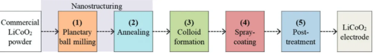
The global water-based colloidal spray-painting process fol-lowed in this work to obtain microelectrodes of pure LiCoO2 on stainless steel disks is schematized in Figure 1.[28] Steps 1 and 2 correspond to the nanostructuring procedure, which con-sists in the grinding (by planetary ball milling, step 1) and the annealing (calcination at 700 °C during 2.5 h, step 2) processes with commercial LiCoO2 powder. The surface of the annealed powder is then modified through dissociative H2O adsorption during storage and water-based colloid preparation (step 3). The “greenest-”wet deposition process[29] developed here involves: the water-based LiCoO2 colloid preparation by ultra-sonic homogenization and without dispersant additives, the air spray coating (step 4), and finally, the post-treatment process at 350 °C during 1 h (step 5).
2.1. Nanostructuring: Planetary Ball Milling and Annealing (Steps 1 and 2)
The most common types of commercial battery grade LiCoO2 powders (Nippon Chemicals, Cellseeds, L106-LICO, Umicore, etc.) have a particle diameter between 2 and 10 µm, which makes almost impossible the obtention of a colloidal dispersion without the use of adequate polymer DAs. Without the steric-stabilization effect of DA, the Brownian motion of these micro-particles in the solvent is dominated by external effects such as gravitation or convection, which leads to particle aggregation and precipitation. With the aim of forming a stable colloidal LiCoO2 dispersion in water, we have considered in this work the use of particles with a particle size distribution (PSD) located in the nanometric domain (between 1 and 1000 nm), through planetary ball milling processing of commercial LiCoO2 (step 1, Figure 1). Unfortunately, it is known that the crystallographic properties of LiCoO2 after ball milling process are significantly degraded.[26] To partially repair those negative impacts, in a next step (step 2, Figure 1), the ball-milled powder was annealed under conditions allowing to maintain the new nanometric PSD.
Figure 2A shows that the planetary ball milling causes an
important shift of the PSD, from a single peak centered on 10 µm to a bimodal distribution with two peaks centered on around 0.15 and 2.0 µm. Annealing at 700 °C produces agglomeration of the
www.advancedsciencenews.com www.advmattechnol.de
smallest particles, decreasing their volume percentage down to 2.0 vol%; in addition, three new maxima are observed at around 0.3, 3.0, and 30.0 µm. These results are consistent with the scan-ning electron microscopy (SEM) images shown in Figure 2. During step 1, the initial LiCoU powder (Figure 2B) is grinded into very small LiCoU45 particles (Figure 2C) with irregular shapes (Figure 2C1). After annealing (step 2), the development of more regular and rounded shapes particles is observed from larger and smoother aggregates up to 5 µm (Figure 2D,D1). These particle morphological changes (schematized in Figure 3D) can be caused by mechanisms of rearrangement and annihilation of crystal defects during annealing, which lead to the decrease of stored energy due to plastic deformation.[30]
Similar morphological changes are reported in literature,[29–32] where commercial LiCoO
2 particles were trans-formed into exfoliated and more disordered structures after ball milling (or rotor-blade grinding) process; this disordering can be partially reversed by simple annealing. The authors observed by X-ray powder diffraction (XRD) measurements that the lay-ered structure of LiCoO2 is damaged following the position and the diminution in intensity of (003) reflection peak (I003),
similar to that observed in the inset of Figure 3A (red peak). In Figure 3A, the XRD pattern of commercial LiCoU powder shows all reflection peaks corresponding to pure high-temper-ature LiCoO2 phase (HT-LiCoO2). These peaks become broader and weaker in intensity after ball milling, indicating a strong diminution of the LiCoO2 crystallinity and showing presum-ably the formation of layer and superficial defects (LiCoU45, Figure 3A).[33] After thermal treatment at 700 °C, all peak intensities are increased, showing partial LiCoO2 crystallinity recovery (LiCoU45-700, Figure 3A). Literature indicates that, during annealing process, the layered structure of LiCoO2 can be partially recovered through ionic migration inside the modified crystal lattice in the bulk and on the LiCoU45 particle surfaces.[26–29] These results show that: i) the annealing process partially repairs the superficial defects and structural dam-ages of the layered LiCoO2 caused by ball milling and ii) after annealing, most of the nanometric particles formed after ball milling are retained, which is indispensable to the water-based colloid preparation.
The layer and superficial defects presumably produced after ball milling and annealing can play an important role in the
Figure 2. A) Particle size distribution (PSD, in vol%) of powders obtained by dynamic light scattering (DLS): (•) the as-received LiCoO2, LiCoU, (•)
sample after grinding, LiCoU45, and (•) sample after annealing, LiCoU45-700. B–D) SEM images of the powders: LiCoU (B), LiCoU45 (C and C1), and LiCoU45-700 (D and D1). The white arrows show the effect of planetary ball milling (step 1) and annealing (step 2).
interaction with air during storage and in the preparation of the water-based LiCoO2 colloid, especially when the specific surface area of LiCoU increases. So, one can expect modifications of the surface properties between samples LiCoU, LiCoU45, and LiCoU45-700 since their specific surface areas are 0.5, 22, and 2 m2 g−1, respectively. Several works examined the interaction between the LiCoO2 electrodes and water through different analytical and theoretical methods:[30–32,34] density functional theory calculations (DFT), microcalorimetry in conjunction with a vapor dosing system, X-ray photoelectron spectroscopy (XPS), synchrotron XPS, and X-ray absorption near edge struc-ture. It has been documented that, under normal conditions, “defect-free” LiCoO2 surfaces have very weak interaction with water, whereas surface defects in layer damaged LiCoO2 struc-tures can strongly increase this interaction.[35] These defects are associated with: i) the coordination, valence, and spin state modification of cobalt (Co3+/Co2+) near the LiCoO
2 surface, ii) the change in Li+ ions mobility from LiCoO2 lattice to LiCoO2 surface, and iii) the Li-antisite (LiCo2−) formation due to the replacement of Co3+ in CoO6 with Li+ at the LiCoO2 surface.
These defects can produce new surface species, such as CoOH, LiOH, Li+(OH)x clusters, CoOOH, Li2O2, Li2O, and Li2CO3 after contact with O2, CO2, and H2O present in ambient air. Attenu-ated total reflectance-Fourier-transform infrared spectroscopy (ATR-FTIR, Figure 3B) and thermal gravimetry (TG, Figure 3C) techniques were used to identify some of these LiCoO2 surface species after ball milling and annealing.
The ATR-FTIR spectra of all samples exhibit the fingerprint of R-3m phase of HT-LiCoO2 in the 550–700 cm−1 region,[33,35–41] where three characteristic bands centered at 558, 584, and 629 cm−1 are identified (asterisks, Figure 3B). After grinding of LiCoU, four new bands are observed in the 800–1500 cm−1 range (LiCoU45, circles, Figure 3B); these bands are typically associated to carbonates (CO32−).[39,42–44] The two bands at 1416 and 1476 cm−1 correspond to the asymmetric CO stretching vibration,[45] while the intense band at 861 cm−1 corresponds to out of plane CO32− bending. Finally, the very weak band at 1085 cm−1 can be assigned to symmetric CO stretching vibra-tion.[42,46] These carbonates are presumably produced from mobile Li+, superficial LiOH, and/or Li2O species and their Figure 3. Comparison of A) XRD patterns, B) ATR-FTIR spectra, and C) TG curves under air (10 mL min−1): of LiCoU (black), LiCoU45 (red), and LiCoU45-700 (blue) powders. In the XRD patterns, the shape and intensity of (003), (101), (006), (102), (104), (015), (017), (018), (110), and (113) peaks correspond to pure HT-LiCoO2 phase (JCPDF No. 44-145) with hexagonal lattice structure (R-3m space group). D) Morphological representation
www.advancedsciencenews.com www.advmattechnol.de
reactions with atmospheric CO2 (Equations (1)–(3)).[38] LiOH can be formed from water dissociation on LiCoO2 (Equation (4) and by simple chemical deintercalation mechanism, as shown in Equation (5).[35] Li
2O and Li2O2 species can be formed through electron transfer from the bulk of LiCoO2 to the super-ficial LiOH and to Li+ species, following Equations (6) and (7), respectively[36] + → + 2LiOH CO2 Li CO2 3 H O2 (1) + → Li O CO2 2 Li CO2 3 (2) + + → + + − 2Li 2CO2 2e Li CO2 3 CO (3) + → + + + Li H O2 LiOH H (4) + → +
LiCoO2 H O2 LiOH CoOOH (5)
+ ++ →− +
LiOH Li e Li O 1/2H2 2 (6)
+ + →
+ −
2Li 2e O2 Li O2 2 (7)
However, the intensity of the carbonate bands decreases sig-nificantly in LiCoU45-700 as a result of annealing at 700 °C. Additionally, the LiCoU45-700 spectrum exhibits a weak and broad band at 1031 cm−1 (x, Figure 3B). Wang and Andrews[47] reported that the antisymmetric stretching vibration mode of linear LiOLi of Li2O can be observed in the 945–1093 cm−1 range. Several reports support the idea that, during thermal treatment, the superficial Li2O can be obtained from Li2O2, Li2CO3, and LiOH with the release of O2, CO2, and H2O, following Equations (8)–(10), respectively[43–45]
→ + Li O2 2 Li O 1/2O2 2 (8) → + 2LiOH Li O H O2 2 (9) → + Li CO2 3 Li O CO2 2 (10)
These thermal transformations in LiCoU45 surface can be observed in the TG curve as shown in Figure 3C: when exposing LiCoU45 to thermal treatment up to 750 °C under air atmos-phere, a total of weight loss of 5.3% is observed; this mass loss can correspond to the water evaporation (T ≈ 100 °C) followed by reactions corresponding to Equations (8) (200–400 °C),[46,48] (9) (250–600 °C),[43,44] and (10) (T > 550 °C).[44,47–49] On the contrary, no significant weight loss is observed in the case of the pristine material (LiCoU, black curve, Figure 3C) in the same temperature range. Finally, the TG curve of the annealed sample (LiCoU45-700, blue curve, Figure 3C) displays a total weight loss of 0.35% only, i.e., 15 times less than that observed for LiCoU45. This suggests a considerable decrease of the car-bonates and other surface species in LiCoU45-700 as a result of annealing. Similarly to what is observed in the ATR-FTIR analysis, Li2CO3 in the LiCo45 surface can be transformed into superficial Li2O after thermal treatment at 700 °C, as shown in Equation (9).
2.2. Water-Based Colloid Preparation (Step 3)
For the colloid preparation, the LiCoU45-700 powder was dis-persed in deionized water with an initial mass concentration, γI, of 20 g L−1. The pH value determined after 90 min of stir-ring was equal to 10.8 (Figure 4A). Under the same conditions and with the same γI, the pH values for LiCoU and LiCoU45 dispersions were 10.2 and 11.8, respectively (Figure 4A). The hydroxide ion comes from LiOH surface species formed through reactions schematized in Equations (4), (5), (11), or (12).[50] [OH−] concentration (log
10[OH−] = pH − 14) observed in the LiCoU45-700 dispersion (0.6 × 10⁻³m) is 10 times lower than the one determined in the LiCoU45 dispersion (6.3 × 10⁻³m) and 4 times larger than in the case of LiCoU (0.15 × 10⁻³m). These results are consistent with ATR-FTIR and TG analysis: i) after ball milling, more surface species, such as LiOH and Li2CO3 (which can be transformed into LiOH through hydr-olysis), are present and this leads to a pH increase when the
Figure 4. A) pH as a function of time for suspensions prepared from LiCoU, LiCoU45, and LiCoU45-700. B,C) Schematic illustrations of stabilization
powder is dispersed in water; ii) the amount of these surface species decreases after annealing at 700 °CL
+ ↔ +
Li CO2 3 2H O2 2LiOH H CO2 3 (11)
+ ↔
Li O H O2 2 2LiOH (12)
Consequently, the zeta potential value, ζ, is affected by these surface species during nanostructuring. Indeed, nega-tive value of ζ increases from −13.8 mV in LiCoU to −33.2 mV in LiCoU45, then ζ decreases to −14.7 mV in LiCoU45-700 after annealing. Considering that ζ corresponds to the elec-trical potential in the interfacial water-particle double layer (as is illustrated in Figure 4C), the increase of ζ in LiCoU45 can correspond to an increase of the surface charge density due to surface species formation after ball milling. After annealing, the surface species amount decreases, which leads to a diminu-tion of the ζ value in LiCoU45-700.
The increase of the negative value of ζ indicates a greater interparticle electrostatic repulsion between adjacent nano-particles. These repulsive Coulombic forces counterbalance the attraction forces due to van der Waals interactions, which can stabilize the water-based colloid formed from powders with higher ζ values (LiCo45 and LiCoU45-700). However, it is also known that other factors such as the pH, the particle morphology, and/or nanoparticles concentration will affect the dispersion homogeneity and the critical coagulation con-centration (CCC) of cathode materials in water-based suspen-sions.[10,22,51–54] The inset in Figure 4A is a photography of three water-based suspensions after ultrasonic treatment (16 h) and decantation (3 h). The formation of a brown and stable colloid is observed for LiCoU45-700 only with a final concentration of 5 g L−1, whereas the formations of supernatant transparent solutions are observed for LiCoU and LiCoU45, as a result of particle aggregation–precipitation. These observations can be explained, on the one hand, by the smallest ζ value in LiCoU sample and its large particle size (monomodal PSD around 10 µm, Figure 2A), which makes almost impossible to form a stable water-based suspension without the use of adequate polymer-dispersants additives (Figure 4B). On the other hand, after ball milling process of LiCoU, both the higher LiCoU45 nanoparticle concentration (PSD, Figure 2A) and the surface species amount (LiOH, Li2CO3, etc.) presumably lead to over-come the CCC in the aqueous suspension. This results in pre-cipitation of the particles, despite a higher ζ value.[51–53]
These results show that, after annealing of LiCoU45, the changes observed in the PSD and surface chemistry favor the formation of a stable water-based colloid and the use of dispersants additives can be totally avoided.
2.3. Spray Coating and Post-Treatment (Steps 4 and 5)
After spray coating (step 4, Figure 1) and post-treatment (step 5, Figure 1), the physicochemical properties of the LiCoO2 electrode, i.e., density, thickness, surface roughness and topology, porosity, specific surface area, PSD, superficial particle morphology, and crystal preferred orientation, were determined.
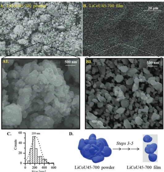
Figure 5 compares SEM images of LiCoU45-700 powder before
colloid preparation (Figure 5A) with LiCoU45-700 film after post-treatment (Figure 5B). It appears that, in the film, aggregates and particles of size between 1.0 and 10.0 µm have disappeared and that the remaining particles are uniformly dispersed on the cur-rent collector. Figure 5C displays the new PSD of LiCoU45-700 after spray coating and post-treatment which produces smooth rounded LiCoO2 nanoparticles with a diameter specifically between 50 and 500 nm (average value around 200 nm). These results show an effect of disaggregation and of particle size selec-tivity toward smaller LiCoO2 particles during water-based colloid preparation (step 3), spray-coating (step 4), and post-treatment processes (step 5). This is schematized in Figure 5D.
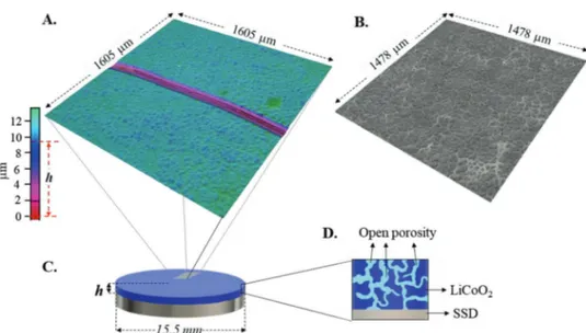
The textural properties of the LiCo45-700 film are summa-rized in Table 1. The thickness (h) and the superficial roughness (Sa) were measured through 3D light scanning microscope image analysis of Figure 6A,B, respectively. From h, the LiCoU45-700 film bulk density (ρh) was calculated according to
Equation (13), where r corresponds to the stainless steel disks (SSD) radius and mLiCoO2 is the mass of LiCoO2 deposited and π(r2)h is the LiCoO
2 film volume (Figure 6C). The packing den-sity percentage or the volume fraction occupied by the LiCoO2 nanoparticles (φ%) can be determined from Equation (14), where ρS corresponds to theoretical single particle density of commercial LiCoO2 (≈5.0 g cm−3)[55] ρ π
( )
= LiCoO 2 2 m r h h (13) φ ρ ρ = × % 100 S h (14)The results show that 54% (φ%) of LiCoO2 film volume is occupied by the LiCoO2 particles and that 46% correspond to void (internal porosity). To verify this, the open porosity (P%) was calculated through Archimedes method and using polyeth-ylene glycol (PEG) as solvent: P% equals 50% for the analyzed film (Table 1). The small difference between the two porosities (≈4%) shows that: i) the thickness of the LiCoO2 film is constant on its whole surface and ii) the internal porosity of the film is fully open (see illustration in Figure 6D). This open porosity is essential to allow the impregnation of the LiCoO2 film with the liquid electrolyte, which can provide a short pathway for ionic transport.
The XRD patterns of 700 powder (blue), LiCoU45-700 film (green), and SSD (black dashed line) are compared in Figure 7A. The shape and intensity of all peaks show that the crystallographic structure of pure HT-LiCoO2 is preserved in the LiCoU45-700 film. However, one observes a very impor-tant intensity increase of the (003) peak in the film com-pared to LiCoU45-700 powder (2.8 times, Figure 7A), while a lower increase (40%) is observed for peak I104 (Figure 7A). Consequently, the I003/I104 value of LiCoU45-700 increases from 2.15 for the powder to 4.40 for the LiCoU45-700 film, which indicates a greater degree of c-axis (003) out-of-plane orientation in the film.
According to literature,[23] this orientation corresponds to a preferred (003) texture, which is observed when the majority of the LiCoO2 grains are spatially oriented with the CoO2 layers
www.advancedsciencenews.com www.advmattechnol.de
parallel to the surface of the current collector (see Figure 7C). Additionally, Zhang et al.[24] and Gao et al.[56] showed that this preferred (003) orientation can be observed when the LiCoO2 grains are spatially oriented with its flat plane parallel to col-lector surface, as is schematized in Figure 7D.
From Ceder and co-workers[57] and Ogumi and co-workers,[58] the preferred (003) texture is an atypical texture for such a thick film (h = 9.5 µm, Table 1). The preferred (003) texture is usually observed when the film is less than 0.5 µm thick as a result of the lowest surface energy of the (003) plane. Based on lattice-model calculations and on polycrystalline films of LiCoO2 deposited by radio-frequency magnetron sputtering, Bates et al.[59,60] have concluded that LiCoO
2 films that are thicker than about 1 µm exhibit strong texturing in which their
(101) and (104) planes are oriented with regard to collector surface, as shown in Figure 7C. This preferred (101)–(104) tex-ture results from the tendency to minimize the volume strain energy developed in the film during the deposition. In fact, to counteract this trend, Zhang et al.[24] used hot-press sintering process at 20 MPa and 950 °C to obtain (003) textured LiCoO2 microelectrodes with a thickness higher than 50 µm. In our case, the preferred (003) texture is obtained at around 9.5 µm thickness without pressing and with a post-treatment tempera-ture of 350 °C only. With the (003) orientation, the CoO2 layers of the LiCoO2 particles will block the Li+ diffusion in the direc-tion perpendicular to the SSD. Therefore Li+ diffusion from the bulk LiCoO2 to the liquid electrolyte must occur in par-allel to SSD surface and thus perpendicularly to the overall Li+ diffusion direction (Figure 7D).
2.4. Electrochemical Characterization
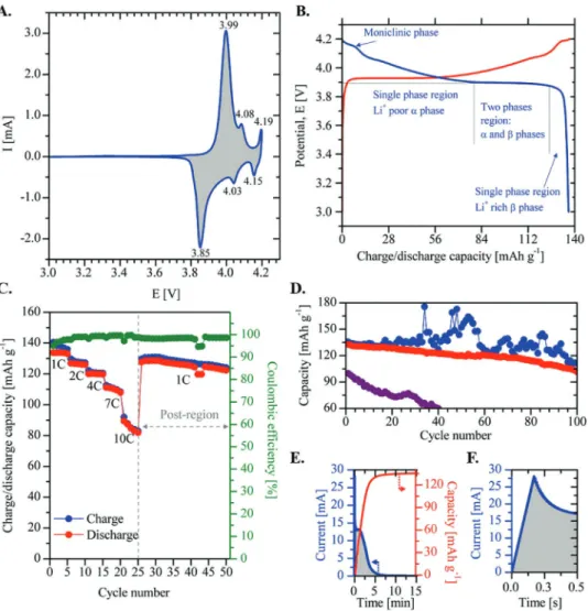
Cyclic voltammogram (CV) in Figure 8A displays the usual oxi-dation/reduction (anodic/cathodic) peaks of well-crystallized
Figure 5. A,B) SEM images of (A) LiCo45-700 powder and (B) LiCo45-700 film. C) PSD on LiCo45-700 film surface. D) Schematic representation of the
LiCo45-700 powder before and after colloid formation (step 3), spray coating (step 4), and post-treatment (step 5).
Table 1. Textural properties of LiCoU45-700 film.
LiCoO2 loading Thickness Roughness Open porosity Bulk density
[mg cm−2] (h [µm]) (S
a [µm]) [P%] (ρh [g cm−3])
HT-LiCoO2 at 3.99/3.85, 4.08/4.03, and 4.19/4.15 V versus Li+/ Li, which are characteristic of the R-3m phase and hexagonal transitions: O3(I), O3(II), and monoclinic, respectively.[57,61] These phase transformations are also detected in the galvano-static capacity profiles of LiCoU45-700 film at C/2 rate between 4.2 and 3.0 V versus Li+/Li (galvanostatic cycling with potential
limitation curves, in Figure 8B). After Li+ deinsertion at constant current (CC, charge, red curve), a maximal capacity value (Q0) of 137.0 mAh g−1 is determined, which is considered as a full state-of-charge (SOC = 100%) with x ≈ 0.5 in LixCoO2. To study the reinsertion mechanism of Li+ during discharge process, the value of x in LixCoO2 was calculated using Equation (15), where
Figure 7. A) XRD patterns of LiCoU45-700 powder, LiCoU45-700 film, and SSD. B) Comparison of XRD patterns in the 18.5°–20.0° region. C) Schematic representation of HT-LiCoO2 crystallographic planes. D) Illustration of Li-ion diffusion in LiCoU-700 film.
Figure 6. A) 3D light scanning microscope image of LiCo45-700 film surface used for thickness measurement (h). B) 3D LSM image of superficial
roughness (Sa) of LiCo45-700 film. C) Illustration of final cathodic electrode (LiCo45-700 film/stainless steel disk (SSD). D) Schematic representation
www.advancedsciencenews.com www.advmattechnol.de
Qt is the discharge capacity at discharge time (t) and Qtheo is the theoretical specific discharge capacity to completely convert LiCoO2 into CoO2 in the electrode (274 mAh g−1)
= 0+ theo
x Q Q Q
t (15)
During discharge (Figure 8B, blue curve), a slight potential decrease, from 4.20 to 3.89 V versus Li+/Li, is observed: this cor-responds to the monoclinic phase formation, usually reported at 4.15 V (x = 0.52). According to the moving boundary model presented by Zhang and White to account for the diffusion-con-trolled phase transition in spherical LiCoO2 solid particles,[62] this slight potential diminution corresponds to Li+ insertion in a single-phase region (Li+ “poor” α-phase) with a Li+ intercala-tion up to x = 0.78 (77.0 mAh g−1). Then, the Li+ intercalation continues until x = 0.95 (124.5 mAh g−1), where a two-phase region is observed (α- and β-phases); this two-phase region is characterized by a well-defined plateau in the discharge profile at 3.89 V versus Li+/Li (for 0.78 ≤ x ≤ 0.95).[59,61,63,64] Finally,
at x > 0.95, the electrode returns to a single phase rich in Li+ (β-phase), where a drastic diminution of potential is displayed to reach the maximum Li+ intercalation at x = 0.99 (136.3 mAh g−1 at 3.0 V vs Li+/Li); this value corresponds to a Coulombic efficiency close to 100%. From literature, these well-defined phase transformations (Figure 8B) are only observed at very low discharge rates: between C/66 and C/10.[62]
This means that at a discharge rate of 5–33 times higher (C/2 rate) and in the total absence of conductive and binder additives (CA and BA), the LiCo45-700 film has the appropriate par-ticle packing density and architecture to allow a complete Li+ de-/ intercalation with a full SOC close to theoretical capacity (x = 0.5 in LixCoO2) and a very high first-cycle Coulombic efficiency.
Figure 8C compares the charge (blue) and discharge (red) capacities (mAh g−1) of the LiCoU45-700 film as a function of number of cycles at rates of 1, 2, 4, 7, and 10 C. The dis-charge capacity slightly decreases to 98% (133 mAh g−1), 92% (125 mAh g−1), and 88% (119 mAh g−1) of full SOC at rates of 1, 2, and 4 C, respectively, which demonstrates high capacity retention at slow cycling rates. At high charge/discharge rates
Figure 8. A) Cyclic voltammetry of LiCoU45-700 film (0.01 mV s−1). B) Charge (red curve) and discharge (blue curve) curves at C/2 rate. C) Charge– discharge capacities obtained at rates of 1, 2, 4, 7, and 10 C (5 cycles each) and at 1 C during the last 25 cycles. D) Charge/discharge capacity of LiCoU45-700 film (blue/red points) and discharge capacity of LiCoU–BA–CA film (violet points). E) Charge (red curve) curve of the first cycle of (D). F) First 0.5 s of charge curve (CVC-mode) of (E).
(7 and 10 C), the capacity fades down to 60% (82 mAh g−1) of SOC; this phenomenon can be due either to redox reactions with the electrolyte or to LiCoO2 structural instability. How-ever, when the rate is fixed at 1 C again, in the “postregion,” the charge capacity increases back to 94% of SOC, with a Cou-lombic efficiency around 98% during the last 25 cycles. In the course of the whole 50 cycles of Figure 8C, the Coulombic efficiency values (>95%) demonstrate that the LiCo45-700 film displays a good reversibility during cycling and that LiCoO2 is structurally stable throughout the Li+ de-/intercalation process.
Finally, to study the cycling stability of the LiCo45-700 film under extreme charge–discharge conditions, a consecutive constant-voltage charging mode (CVC-mode, blue points on Figure 8D) was first applied for fast charging; then, a galvano-static discharge mode at 10 C was used during 100 cycles. In the charging mode, the potential is maintained during 15 min at 4.2 V versus Li+/Li (cut-off value) for each cycle. At such high charge and discharge rates, the risk of failure of the cell is very high due to the intense current peaks in the first stages of charging, which can lead to irreversible structural damages of LiCoO2. Also, this can produce high overcharges leading to sev-eral catastrophic events:[60,65] i) collapse of the layered LiCoO
2 structure, ii) release of oxygen, iii) oxidative decomposition of the electrolyte solvents, and consequently, iv) thermal runaway in the cell. Results of this charge–discharge program are shown in Figure 8D. In the course of the whole 100 cycles and during the first seconds of each CVC-mode, current peaks between 15.6 and 33.5 mA were observed, as shown in Figure 8E,F. This inset displays both the behavior of current (blue) and the charge capacity (red) as a function of time during the first constant-voltage charge, where a current peak of 28.0 mA is observed after 0.16 s of charge. The capacity curve shows that 98.8% of SOC (135.5 mAh g−1) is reached after 15 min.
A similar behavior is observed during the first 20 cycles without important overcharges (Figure 8D): the charge (blue) and discharge (red) capacities are almost superimposed. Unfortu-nately, high and irregular overcharges up to about 175.6 mAh g−1 (128% of SOC) are observed during the last 80 cycles: this can lead to extended lithium extraction causing irreversible struc-tural and morphological changes in the LiCoU45-700 film. However, i) a remarkable discharge capacity was observed at the first cycle (132.8 mAh g−1, i.e., 96.9% of SOC) and ii) the dis-charge capacity was still 101.6 mAh g−1 (74.2% of SOC) after 100 cycles. This corresponds to 0.22% decay per cycle only at a rate of 10 C. On the contrary, a rapid loss in discharge capacity is observed in the LiCoU–BA–CA film fabricated by the con-ventional method (using NMP as solvent) during the first 40 cycles (violet points in Figure 8D). Its initial discharge capacity decreases from 100.7 up to 61.6 mAh g−1. These results demonstrate that the LiCoU45-700 film displays the necessary physicochemical characteristics to favor the Li+ intercalation at fast discharge rates, despite the very high current peaks and extended overcharges. In our opinion, this is due to the sum of factors such as: i) the recovered layers structure of LiCoO2 after annealing process (HT-LiCoO2 with preferred (003) orienta-tion, Figure 7), ii) the particle nanosized distribution (centered at 200 nm, Figure 5C), iii) the packing density percentage (φ% = 54%), and (iv) the open porosity (50%, Figure 6D) of the final LiCoU45-700 film.
Regarding the existence of a preferred (003) orientation suggested from XRD, an additional argument comes from Li+ diffusion coefficient value comparison. The Li+ diffusion coefficient (DLi= 1.2 × 10⁻¹² cm2 s−1) calculated from electro-chemical impedance spectroscopy (EIS) analysis[66–69] (Figure S1 and Equation (S1), Supporting Information) is consistent with those DLi values determined by Yamamoto and co-workers[70] on thin films electrodes of pure Li
0.5CoO2 (1.6 × 10⁻¹³ < DLi < 1.6 × 10⁻¹⁰ cm2 s−1). These highly dense electrodes have a (003) preferred orientation (with the CoO2 layers parallel to substrate, Figure 7C), and a thickness of 310 nm, which is a value close to LiCoU45-700 particles mean size (200 nm). In addition, in highly dense electrodes of Yamamoto and co-workers with a higher thickness of 1.35 µm and with a (104) preferred orientation (with the CoO2 layers perpendicular to substrate, Figure 7C), higher Li+ diffusion coefficients, between 1.8 × 10⁻¹¹ and 6.4 × 10⁻¹⁰ cm2 s−1, were determined.[70] The authors evidenced that the increase of DLi is explained by the crystal structure orientation of LiCoO2: in the (104) oriented LiCoO2, the Li layers lie parallel to the direction of Li+ diffusion (red arrow in Figure 7C), while in the (003) oriented film, the Li layers lie perpendicular to the direction of Li+ diffusion. As a consequence, the similarity of DLi values in LiCoU45-700 film and in (003) oriented film of Yamamoto and co-workers tends to prove that this (003) orientation also prevails in LiCoU45-700 film which should therefore exhibit a preferred orientation the CoO2 layers which is perpendicular to Li+ diffusion direction and thus parallel to the stainless steel surface.
In summary, these analyses suggest that DLi could be even more improved in LiCoU45-700 film if its CoO2 layers were parallel to the Li+ diffusion direction, that is, with a preferred (104) or (003/004) orientation, which would be a very inter-esting challenger for future research.
3. Conclusion
Through the application of a simple ball milling and annealing process (nanostructuring) on microstructured LiCoO2 powder, we have demonstrated that: i) a stable water-based colloidal sus-pension of nanostructured LiCoO2 particles can be obtained via interparticle electrostatic repulsion and, consequently, the use of dispersant additives can be totally avoided; ii) this colloid can be used to produce electrodes of pure LiCoO2 without conductive and binder additives, via spray coating. The final electrodes can be used for manufacturing high-rate lithium-ion batteries.[71]
After ball milling process, it has been demonstrated that: i) a high population of LiCoO2 particles with nanosized dis-tribution is generated from LiCoO2 microparticles of around 10 µm diameter; ii) these nanoparticles suffered a great damage and loss of crystallographic layered structure; iii) a sig-nificant amount of LiCoO2 superficial defects is formed. After annealing process at 700 °C, it has been confirmed that: i) a large portion of the nanometric particles size distribution is maintained, despite the formation of large aggregates; ii) the damages on LiCoO2 layered structure and on superficial defects formation are repaired partially; iii) the interaction between atmospheric O2, CO2, and H2O and the remaining superficial defects produces Li2CO3 and other alkali superficial species;
www.advancedsciencenews.com www.advmattechnol.de
and iv) the zeta potential is increased due the presence of these superficial species, which indicate a higher interparticle electro-static repulsion between adjacent LiCoO2 nanoparticles during the colloid formation in water. In consequence, a stable water-based colloidal suspension with well-dispersed and smooth and rounded LiCoO2 nanoparticles is obtained.
The electrochemical performance analysis demonstrated that the architecture of electrodes prepared from pure LiCoO2 obtained after nanostructuration, colloid formation, and spray coating allows for fast ion and electron transport necessary to fast rechargeable lithium-ion batteries.[71] The architecture of the electrode film simultaneously provides: i) an interconnected electrolyte-filled pore network through an open porosity of 50% that enables rapid ion transport; ii) a short solid-phase ion dif-fusion length, thanks to the nanostructuring process (average particle size around 200 nm), minimizing the effect of slug-gish solid-state ion transport; iii) a recovered layers structure of LiCoO2 nanoparticles (HT-LiCoO2 phase) after annealing of ball-milled powders; and iv) a homogeneous LiCoO2 particle packing density (2.7 g cm−3, 9.5 µm thickness) guarantees an efficient electron transfer in the entire electrode and offers a high physicochemical stability.
4. Experimental Section
Nanostructuring – Ball Milling and Annealing: Commercial
battery-grade LiCoO2 powder, supplied by Umicore (6.0 g, referred to as
LiCoU), was milled in a FRITSCH pulverisette planetary ball mill, using 100 g of stainless steel balls (diameter of 3 mm) in a stainless steel grinding bowl of 80 mL. Milling was carried out in 20 cycles at 450 rpm for 5 min and 5 min of pause by cycle. The ground sample before heat treatment was referred to as LiCoU45. LiCoU45 was further calcined at 700 °C at a rate of 10 °C min−1 under flowing air (0.1 mmol s−1) and the
temperature was maintained for 2.5 h. The calcined sample was referred to as LiCoU45-700.
Water-Based Colloid Preparation: The colloidal suspension was
prepared at 25 °C by direct dispersion of LiCoU45-700 powder (6.0 g) in 300 mL of deionized water. The suspension was stirred for 90 min (while pH was monitored), then ultrasonicated in a water bath (42 kHz) for 16 h. The solid in excess was separated from the suspension after 3 h of decanting. The final colloidal suspension was referred to as LiCo-colloid. This suspension was maintained under continuous stirring until spray painting. The final concentration of LiCo-colloid was 5 g L−1, which
was determined by gravimetric analysis after water evaporation. As comparison, LiCoU and LiCoU45 powders were also dispersed under the same conditions; however, no stable colloidal suspension was obtained.
Spray Painting: LiCoU45-700 electrodes were manufactured by
spraying LiCo-colloid on SSD (1.88 cm2 in diameter and 0.5 mm thick)
using an air-jet spray valve type 781S (Nordson EFD, air pressure: 6.2 MPa) equipped with an input fluid pressure of 1.5 MPa. The surface temperature of the SSD was maintained at 100 °C using a hot plate.
Post-Treatment: The electrodes were heated at 350 °C at a rate of 10 °C min−1 under flowing air (0.1 mmol s−1) and the temperature was
maintained for 1 h. The calcined electrodes were referred to as LiCoU45-700 film. Finally, the amount of deposited active material was comprised between 2.0 and 3.0 mg cm−2. Electrode loadings were measured by weighing the electrode and subtracting the mass of the SSD.
Characterization: All products (powders and films) were characterized
by X-ray powder diffraction (Siemens D5000 powder diffractometer, CuKα radiation) and scanning electron microscopy (Philips ESEM-XL30). The particle size distributions of the powders were obtained by laser diffraction by using a Mastersizer 2000 (Malvern Instruments) in wet mode (Hydro2000). TG measurements were performed in a Setaram
TG-DSC 111 thermoanalyzer under air (10 mL min−1): the samples were
heated from 20 to 800 °C at 2 °C min−1 in a 100 µL platinum crucible (an
empty crucible was used as the reference). FTIR analysis in conjunction with ATR; to that aim a Spectrum One FT-IR Spectrometer (PerkinElmer) was used. Optical 3D-measurements of 3D thickness (h) and surface roughness (Sa) of the film were obtained with an Infinite Focus
microscope (Alicona). The open porosity of the film was determined by Archimedes’ method using PEG (average M.W. 200, Acros Organics, ρPEG= 1.125 g cm−3) as solvent. The electrode was immersed in the
PEG for 2 h. After removing the excess of PEG from the electrode with filter paper, the amount of PEG adsorbed was determined by weighing. All powders were characterized by performing nitrogen adsorption– desorption isotherm analysis at −196 °C on a Micromeritics ASAP 2420 instrument. The total specific surface area of LiCoU, LiCoU45, and LiCoU45-700 powders were calculated by applying the Brunauer– Emmett–Teller theory: 0.3, 22.7, and 2.6 m2 g−1, respectively.
The electrochemical properties of the products were investigated on a multichannel battery tester (Bio-Logic VMP3) using CR2032 coin-type cells. The coin cell batteries were assembled in an argon-filled glove box (MBraun 200B) with the LiCoU45-700 film as positive electrode, a Li metal foil as counter and reference electrode, a layer of separators (2 Celgard 2730 membranes), and two stainless steel disks as fillers. 1 m LiPF6 in ethylene
carbonate/diethylcarbonate (1:1, w/w, Merck) was used as electrolyte. CVs were measured at a scan rate of 0.1 mV s−1 between 3.0 and 4.2 V
versus Li/Li+. EIS (Figure S1, Supporting Information) measurement was
performed at constant voltage (4.2 V), at 100% SOC (after charge at C/2 rate) in the AC frequency (from 1 MHz to 0.2 Hz). Galvanostatic cycling was performed between 3.0 and 4.2 V versus Li/Li+ at 0.5, 1, 2, 4, 8, and
10 C rates. The CVC-charge/CC-discharge cycling protocol was performed using a constant-voltage charge mode at 4.2 V for a fixed time of 15 min by cycle (CVC-mode) and a constant-current discharge at 10 C (between 3.0 and 4.2 V vs Li/Li+) during 100 cycles. For comparison purposes, LiCoU
electrodes (commercial battery-grade LiCoO2 powders) were prepared via
a conventional method using an organic ink (PVDF as BA, active carbon as CA, and NMP as solvent: LiCoU–BA–CA film) that was spread on a SSD surface by means of a bar coater (Elcometer 4340 Automatic film applicator), the opening of the knife being adjusted at 150 mm. Then, LiCoU/SSD electrode was dried at ambient temperature during 3 h and at 60 °C overnight. The deposed mass of a LiCoU was of 3.0 mg cm−2.
Supporting Information
Supporting Information is available from the Wiley Online Library or from the author.
Acknowledgements
This work was supported by the Walloon Region (Phosphagel project, Grant No. 0917013 and ENSOwal project), the EU H2020 ECSEL program (ENSO project, Grant No. 692482), and by Prayon S.A. through private funding.
Conflict of Interest
The authors declare no conflict of interest.
Keywords
LiCoO2 films, spray-coating, water-based colloids
Received: June 12, 2019 Revised: August 13, 2019 Published online:
[1] F. Y. Su, L. Q. Dai, X. Q. Guo, L. J. Xie, G. H. Sun, C. M. Chen,
J. Energy Storage 2017, 14, 82.
[2] D. L. W. Iii, J. Li, C. Daniel, J. Power Sources 2015, 275, 234. [3] W. Lai, C. K. Erdonmez, T. F. Marinis, C. K. Bjune, N. J. Dudney,
F. Xu, R. Wartena, Y. M. Chiang, Adv. Mater. 2010, 22, E139. [4] G. W. Lee, J. H. Ryu, W. Han, K. H. Ahn, S. M. Oh, J. Power Sources
2010, 195, 6049.
[5] W. Porcher, B. Lestriez, S. Jouanneau, D. Guyomard, J. Electrochem.
Soc. 2009, 156, A133.
[6] C.-C. Li, Y.-W. Wang, J. Electrochem. Soc. 2011, 158, A1361.
[7] L. Wang, J. Ma, C. Wang, X. Yu, R. Liu, F. Jiang, X. Sun, A. Du, X. Zhou, G. Cui, Adv. Sci. 2019, 6, 1900355.
[8] A. Guerfi, M. Kaneko, M. Petitclerc, M. Mori, K. Zaghib, J. Power
Sources 2007, 163, 1047.
[9] J. T. Li, Z. Y. Wu, Y. Q. Lu, Y. Zhou, Q. Sen Huang, L. Huang, S. G. Sun, Adv. Energy Mater. 2017, 1701185.
[10] J. Li, B. L. Armstrong, J. Kiggans, C. Daniel, D. L. Wood,
J. Electrochem. Soc. 2013, 160, A201.
[11] N. Rey-Raap, M. L. C. Piedboeuf, A. Arenillas, J. A. Menéndez, A. F. Léonard, N. Job, Mater. Des. 2016, 109, 282.
[12] C. A. Paez, D. Liquet, D. Eskenazi, J.-P. Pirard, B. Heinrichs, WO
Patent 2013/1712A2, 2013.
[13] C.-C. Li, X.-W. Peng, J.-T. Lee, F.-M. Wang, J. Electrochem. Soc. 2010,
157, A517.
[14] S. S. Zhang, K. Xu, T. R. Jow, J. Power Sources 2004, 138, 226. [15] A. F. Léonard, N. Job, Mater. Today Energy 2019, 12, 168.
[16] K. Wu, Y. Wang, I. Zhitomirsky, J. Colloid Interface Sci. 2010, 352, 371.
[17] C. C. Li, J. T. Lee, Y. L. Tung, C. R. Yang, J. Mater. Sci. 2007, 42, 5773. [18] A. Kohut, A. Voronov, W. Peukert, Langmuir 2007, 23, 504. [19] A. Kraytsberg, Y. Ein-Eli, Adv. Energy Mater. 2016, 6, 1600655. [20] V. Wenzel, H. Nirschl, D. Nötzel, Energy Technol. 2015, 3, 692. [21] G. Liu, H. Zheng, X. Song, V. S. Battaglia, J. Electrochem. Soc. 2012,
159, A214.
[22] H. Zheng, R. Yang, G. Liu, X. Song, V. S. Battaglia, J. Phys. Chem. C
2012, 116, 4875.
[23] J. T. Lee, Y. J. Chu, F. M. Wang, C. R. Yang, C. C. Li, J. Mater. Sci.
2007, 42, 10118.
[24] H. Zhang, P. J. Baker, P. S. Grant, J. Am. Ceram. Soc. 2010, 1859, 1856.
[25] S. Shiraki, H. Oki, Y. Takagi, T. Suzuki, A. Kumatani, R. Shimizu, M. Haruta, T. Ohsawa, Y. Sato, Y. Ikuhara, T. Hitosugi, J. Power
Sources 2014, 267, 881.
[26] W. G. Choi, S. G. Yoon, J. Power Sources 2004, 125, 236.
[27] M. Hayashi, M. Takahashi, Y. Sakurai, J. Power Sources 2007, 174, 990.
[28] C. A. Paez, D. Liquet, C. Calberg, B. Heinrichs, C. Allié, WO Patent 2016/097396 Al, 2016.
[29] D. Prat, A. Wells, J. Hayler, H. Sneddon, C. R. McElroy, S. Abou-Shehada, P. J. Dunn, Green Chem. 2015, 18, 288.
[30] P. R. Rios, F. Siciliano Jr., H. R. Z. Sandim, R. L. Plaut, A. F. Padilha,
Mater. Res. 2005, 8, 225.
[31] R. Alcántara, G. F. Ortiz, P. Lavela, J. L. Tirado, W. Jaegermann, A. Thißen, J. Electroanal. Chem. 2005, 584, 147.
[32] M. N. Obrovac, O. Mao, J. R. Dahn, Solid State Ionics 1998, 112, 9. [33] J. Geder, H. E. Hoster, A. Jossen, J. Garche, D. Y. W. Yu, J. Power
Sources 2014, 257, 286.
[34] K. Nakamura, H. Hirano, D. Nishioka, Y. Michihiro, T. Moriga, Solid
State Ionics 2008, 179, 1806.
[35] G. Cherkashinin, W. Jaegermann, J. Chem. Phys. 2016, 144, 184706. [36] M. Motzko, M. A. Carrillo Solano, W. Jaegermann, R. Hausbrand,
J. Phys. Chem. C 2015, 119, 23407.
[37] P. S. Maram, G. C. C. Costa, A. Navrotsky, Angew. Chem., Int. Ed.
2013, 52, 12139.
[38] N. Mijung, Y. Lee, J. Cho, J. Electrochem. Soc. 2006, 153, A935. [39] R. Alcántara, P. Lavela, J. L. Tirado, R. Stoyanova, E. Zhecheva,
J. Solid State Chem. 1997, 134, 265.
[40] W. Huang, R. Frech, Solid State Ionics 1996, 86–88, 395.
[41] H. Porthault, R. Baddour-Hadjean, F. Le Cras, C. Bourbon, S. Franger, Vib. Spectrosc. 2012, 62, 152.
[42] Y. Bai, K. Jiang, S. Sun, Q. Wu, X. Lu, N. Wan, Electrochim. Acta
2014, 134, 347.
[43] Z. Wang, X. Huang, L. Chen, J. Electrochem. Soc. 2004, 151, A1641. [44] J. Kim, M. Kim, S. Noh, G. Lee, D. Shin, Ceram. Int. 2016, 42,
2140.
[45] A. Boulant, J. F. Bardeau, A. Jouanneaux, J. Emery, J. Y. Buzare, O. Bohnke, Dalton Trans. 2010, 39, 3968.
[46] L. Fan, D. Tang, D. Wang, Z. Wang, L. Chen, Nano Res. 2016, 9, 3903.
[47] X. Wang, L. Andrews, Mol. Phys. 2009, 107, 739.
[48] H. Li, X. Jiao, L. Li, N. Zhao, F. Xiao, W. Wei, Y. Sun, B. Zhang,
Catal. Sci. Technol. 2015, 5, 989.
[49] H. Kudo, J. Nucl. Mater. 1979, 87, 185.
[50] J. Kim, Y. Hong, K. S. Ryu, M. G. Kim, J. Cho, Electrochem.
Solid-State Lett. 2006, 9, A19.
[51] H. Beyer, S. Meini, N. Tsiouvaras, M. Piana, H. A. Gasteiger, Phys.
Chem. Chem. Phys. 2013, 15, 11025.
[52] K. Park, J. H. Park, S. G. Hong, B. Choi, S. Heo, S. W. Seo, K. Min, J. H. Park, Sci. Rep. 2017, 7, 1.
[53] J.-W. Kim, Y.-D. Lee, H.-G. Lee, ISIJ Int. 2001, 41, 116. [54] D. Zhou, A. A. Keller, Water Res. 2010, 44, 2948. [55] J. Akimoto, Y. Gotoh, J. Solid State Chem. 1998, 141, 298.
[56] S. Gao, W. Wei, M. Ma, J. Qi, J. Yang, S. Chu, J. Zhang, L. Guo, RSC
Adv. 2015, 5, 51483.
[57] H. Xia, Y. S. Meng, L. Lu, G. Ceder, Sci. Commons 2007, http:// en.scientificcommons.org/20613936.
[58] Y. Iriyama, M. Inaba, T. Abe, Z. Ogumi, J. Power Sources 2001, 94, 175.
[59] F. X. Hart, J. B. Bates, J. Appl. Phys. 1998, 83, 7560.
[60] J. B. Bates, N. J. Dudney, B. J. Neudecker, F. X. Hart, H. P. Jun, S. A. Hackney, J. Electrochem. Soc. 2000, 147, 59.
[61] J. P. Hsu, B. T. Liu, J. Colloid Interface Sci. 1998, 198, 186. [62] Q. Zhang, R. E. White, J. Electrochem. Soc. 2007, 154, A587. [63] J.-P. Hsu, B.-T. Liu, J. Phys. Chem. B 1998, 102, 334. [64] K. Tamura, E. Tatsukawa, J. Appl. Electrochem. 2017, 47, 381. [65] T. Azib, F. Le Cras, H. Porthault, Electrochim. Acta 2015, 160, 145. [66] G. GirishKumar, W. H. Bailey, B. K. Peterson, W. J. Casteel, J.
Electro-chem. Soc. 2011, 158, A146.
[67] L. Wang, B. Chen, J. Ma, G. Cui, L. Chen, Chem. Soc. Rev. 2018, 47, 6505.
[68] Y. Sun, J. Tang, K. Zhang, J. Yuan, J. Li, D. M. Zhu, K. Ozawa, L. C. Qin, Nanoscale 2017, 9, 2585.
[69] J. Zhao, L. Wang, X. He, C. Wan, C. Jiang, Int. J. Electrochem. Sci.
2010, 5, 478.
[70] J. Xie, N. Imanishi, A. Hirano, M. Matsumura, Y. Takeda, O. Yamamoto, Solid State Ionics 2007, 178, 1218.
[71] Y. Tang, Y. Zhang, W. Li, B. Ma, X. Chen, Chem. Soc. Rev. 2015, 44, 5926.