HAL Id: hal-02322217
https://hal.archives-ouvertes.fr/hal-02322217
Submitted on 9 Dec 2020HAL is a multi-disciplinary open access archive for the deposit and dissemination of sci-entific research documents, whether they are pub-lished or not. The documents may come from teaching and research institutions in France or abroad, or from public or private research centers.
L’archive ouverte pluridisciplinaire HAL, est destinée au dépôt et à la diffusion de documents scientifiques de niveau recherche, publiés ou non, émanant des établissements d’enseignement et de recherche français ou étrangers, des laboratoires publics ou privés.
Electrochemical study of asymmetric aqueous
supercapacitors based on high density oxides:
C/Ba0.5Sr0.5Co0.8Fe0.2O3-δ and
FeWO4/Ba0.5Sr0.5Co0.8Fe0.2O3-δ
Pierre Lannelongue, Steven Le Vot, Olivier Fontaine, Thierry Brousse,
Frédéric Favier
To cite this version:
Pierre Lannelongue, Steven Le Vot, Olivier Fontaine, Thierry Brousse, Frédéric Favier. Electrochemical study of asymmetric aqueous supercapacitors based on high density oxides: C/Ba0.5Sr0.5Co0.8Fe0.2O3-δ and FeWO4/Ba0.5Sr0.5Co0.8Fe0.2O3-δ. Electrochimica Acta, Elsevier, 2019, 326, pp.134886. �10.1016/j.electacta.2019.134886�. �hal-02322217�
Electrochemical study of asymmetric aqueous
supercapacitors based on high density oxides: C/
Ba
0.5Sr
0.5Co
0.8Fe
0.2O
3-δand
FeWO
4/Ba
0.5Sr
0.5Co
0.8Fe
0.2O
3-δPierre Lannelongue1,3, Steven Le Vot1,3, Olivier Fontaine1,3, Thierry
Brousse2,3 and Fréderic Favier1,3,*
1 Institut Charles Gerhardt Montpellier (ICGM), UMR 5253, Université de Montpellier,
CNRS, 34095 Montpellier Cedex 5, France
2 Institut des Matériaux Jean Rouxel (IMN), UMR 6502, Université de Nantes, CNRS, 44322
Nantes Cedex 3, France
3 Réseau sur le Stockage Electrochimique de l’énergie (RS2E), FR CNRS 3459, France
*frederic.favier@umontpellier.fr
Abstract
Two asymmetric aqueous electrochemical capacitors operated in 5M LiNO3 are reported:
C/Ba0.5Sr0.5Co0.8Fe0.2O3-δδ (BSCF) and FeWOBSCF) and FeWO4/BSCF, with activated carbon and FeWO4
(BSCF) and FeWOsynthesized by a precipitation method) as negative electrodes, respectively, and BSCF (BSCF) and FeWOsynthesized by a modified glycine-δnitrate process) as positive electrodes. These two devices were operated between 0 and 1.6 V and between 0 and 1.4 V, respectively. They demonstrated a remarkable cycling ability with a high capacitance retention over 10,000 and 45,000 cycles, respectively. Thanks to the high density of BSCF, the C/BSCF device exhibits a volumetric energy density up to 2.7 Wh.L-δ1 at low current densities. This study demonstrates
the advantages and limits of the use of high density multicationic oxides with pseudocapacitive behavior to improve the volumetric energy density of aqueous electrochemical capacitors.
Keywords
Aqueous electrochemical capacitors; Supercapacitors; Asymmetric devices; Volumetric energy density; BSCF; FeWO4; Perovskite.
1. Introduction
Electrochemical capacitors, also called supercapacitors, present intermediate performance between batteries and conventional capacitors [1 ]. Currently, commercialized electrochemical capacitors are electrochemical double layer capacitors (BSCF) and FeWOEDLCs) using activated carbon as electrodes. Their specific energy and power densities are about 10 Wh.kg-δ1[1 ] and 10 kW.kg-δ1
[2 ], respectively. However, their volumetric energy density is low, typically between 5 and 7 Wh.L-δ1. As such, EDLCs are not the ideal devices for power applications where the volume
dedicated to energy storage is limited, such as in modern electrical terrestrial vehicles. Another type of electrochemical capacitors has been developed over the past two decades, using materials showing a pseudocapacitive behavior. The pseudocapacitive charge storage process induces a similar electrochemical signature to that of capacitive process, but its origin is faradic and involves fast and reversible redox reactions [1,3]. Such behavior has been observed for various electrode materials including metal oxides such as RuO2 [4-6 ], MnO2 [7-
9 ], Fe3O4 [10,11], but also nitrides such as VN [12,13] and MoxN [14 ], conducting polymers
[15 ] or Mxenes [16 ]. Thanks to their high density compared to that of activated carbon, pseudocapacitive oxides are attractive materials to improve the volumetric energy density of electrochemical capacitors. As such, Goubard-δBretesché et al. predicted a volumetric energy density of a symmetrical electrochemical capacitor MnO2/MnO2 (BSCF) and FeWObulk density: 4.5 g.cm-δ3)
twice greater than that of a symmetrical carbon/carbon device (BSCF) and FeWObulk density: 2.09-δ2.23 g.cm-δ3)
Thus, high density pseudocapacitive oxides have to be considered to improve the volumetric energy density of electrochemical capacitors. This is in the last few years only that multicationic oxides have been studied as electrode materials for electrochemical capacitors
[18 ]. Among them, ABO3 perovskite materials [19-23 ], AB2O4 spinel materials [24-27 ],
MWO4 tungstate materials [28 ] or A2B2O7 pyrochlore materials [29 ] have been considered.
These materials present high densities but also specific capacitances close to that of standard activated carbon. In previous papers, some of us have reported the attractive properties of two oxides to be used as electrode materials for electrochemical capacitors: FeWO4 [28 ] and
Ba0.5Sr0.5Co0.8Fe0.2O3-δδ, so called BSCF [30 ]. An asymmetric aqueous electrochemical
capacitors with a FeWO4 negative electrode material has already been tested using MnO2 as
the positive electrode [31 ]. This device presents a specific capacitance of 9 F.g-δ1 (BSCF) and FeWOtotal weight
of both electrodes) at 20 mV.s-δ1 in 5M LiNO
3 with a high cycling ability over 40,000 cycles.
The crystallographic density of FeWO4 and BSCF materials is 7.5 and 5.8 g.cm-δ3, respectively,
i.e. 6 to 7 times greater than that of standard activated carbon. As such, both materials present
high volumetric capacitance in aqueous medium (BSCF) and FeWO5M LiNO3). Furthermore, their respective
operational potential windows are complementary (BSCF) and FeWO-δ0.6 – 0 V vs Ag/AgCl for FeWO4 and 0 –
0.8 V vs Ag/AgCl for BSCF). Thus, it seems interesting to evaluate the volumetric performance of such electrochemical capacitor devices built from these two electrode materials.
Electrochemical capacitor devices with BSCF positive electrodes have never been reported in the literature. As such, we report hereafter the study of two asymmetric devices: the first one associates an activated carbon electrode with a BSCF electrode (BSCF) and FeWOC/BSCF) and the second one associates FeWO4 and BSCF electrodes (BSCF) and FeWOFeWO4/BSCF). Both devices were operated in
aqueous 5M LiNO3 electrolyte. Several devices have been built and tested to determine the
compromise between performances and electrochemical stability window of each electrode. Specific and volumetric performance and cycling ability of these devices have been evaluated by galvanostatic cycling. Self-δdischarge measurements have been performed by a chronoamperometry/chronopotentiometry routine. Performance of these devices are commented to argue on the interest of using high density electrode materials to improve the volumetric energy density of electrochemical capacitors.
2. Experimental section
2.1. Materials
Ba0.5Sr0.5Co0.8Fe0.2O3-δδ– BSCFBSCF
All precursors were purchased from Sigma Aldrich. Precursors mass used are listed in
Tab.S1. BSCF was prepared by a modified glycine-δnitrate process. Ba(BSCF) and FeWONO3)2 (BSCF) and FeWOACS Reagent,
≥99%), Sr(BSCF) and FeWONO3)2 (BSCF) and FeWOACS Reagent, ≥99%), Co(BSCF) and FeWONO3)2,6H2O (BSCF) and FeWOACS Reagent, ≥98%) and
Fe(BSCF) and FeWONO3)3,9H2O (BSCF) and FeWOACS Reagent, ≥98%) were dissolved in stoichiometric quantities in distilled
water at 100°C and under vigorous stirring. A red solution is obtained. After dissolution, glycine (BSCF) and FeWOACS Reagent, ≥98.5%), acting as complexing agent and fuel, was added to the solution. Ten minutes after glycine dissolution, ethylenediaminetetraacetique acid EDTA, acting as complexing agent (BSCF) and FeWOanhydrous, ≥99%) was added. The stoichiometry quantities of glycine and EDTA were determined following reactions pathways (BSCF) and FeWO1) and (BSCF) and FeWO2) respectively:
0.5 Ba(BSCF) and FeWONO3)2 + 0.5 Sr(BSCF) and FeWONO3)2 + 0.8 Co(BSCF) and FeWONO3)2 + 0.2 Fe(BSCF) and FeWONO3)3 + 2.13 HOOC-δCH2-δNH2
↓ (1)
Ba0.5Sr0.5Co0.8Fe0.2O3 + 4.26 CO2 + 5.33 H2O + 3.165 N2
0.5 Ba(BSCF) and FeWONO3)2 + 0.5 Sr(BSCF) and FeWONO3)2 + 0.8 Co(BSCF) and FeWONO3)2 + 0.2 Fe(BSCF) and FeWONO3)3 + 0.48 C10H16N2O8
↓ (2)
In order to synthesize large amounts of BSCF, expected glycine and EDTA masses were multiplied by 2.5 and 2, respectively. After EDTA dissolution, a 60 mL purple-δblack solution is obtained. At the end of the water evaporation (BSCF) and FeWOabout one hour), the gelification process started. The gel was then transferred in an oven at 600°C under air atmosphere where a combustion took place 10 minutes later. Resulting ashes were kept at 600°C for one hour to remove carbon residues. Finally, ashes were manually ground and heated at 850°C for 10 hours.
FeWO4
FeWO4 was synthesized by a precipitation method. Two equimolar 15 mL solutions of
FeCl2.4H2O (BSCF) and FeWOpuriss. p.a., ≥99%) and Na2WO4.2H2O (BSCF) and FeWOACS Reagent, ≥99%), both from Sigma
Aldrich were prepared. Precursor mass used are listed in Tab.S2. The iron chloride solution was heated at 70°C under magnetic stirring for 10 minutes. Then, the sodium tungstate was added dropwise into the iron chloride solution leading to a brow precipitate. The resulting solution was kept at 70°C under magnetic stirring for 3 hours. The precipitate was recovered by filtration before being washed three times with distilled water and subsequently three times with ethanol.
Activated BSCFcarbon
Activated carbon was purchased from ACS Material. The particle average size is 5 µm.
Activated carbon from ACS Material is mesoporous with a pore size distribution from 2 to 2.2 nm and its BET specific surface area is 2,000 m².g-δ1.
2.2.BSCF and FeWO4 powder characterizations
Prepared BSCF and FeWO4 powders were characterized by X-δray diffraction using a
PANalytical X’Pert in the Bragg-δBrentano configuration with CuKα radiation, from 10 to 90°α radiation, from 10 to 90° with a step angle of 0.032°. Their morphology were observed by scanning electron microscopy on a Hitachi S4800. BSCF composition was evaluated by EDS analysis.
2.3.Electrode preparation
Electrodes were prepared by mixing active materials with acetylene black (BSCF) and FeWOAlfa Aesar) and PTFE (BSCF) and FeWO60 wt% dispersed in water, Sigma Aldrich) in ethanol. Mass ratios (BSCF) and FeWOactive material: acetylene black: PTFE) were 60:30:10 for BSCF and FeWO4 based electrodes and 75:15:10
for activated carbon based electrodes. After ethanol evaporation at 60°C under magnetic stirring, the resulting paste was repeatedly cold rolled until a homogeneous film was obtained. A 10 mm diameter disk was cut off from the film and pressed at 10 tons onto a folded stainless steel grid. For asymmetric devices (BSCF) and FeWOSwagelok type), electrode films were pressed onto nickel foam at 10 tons. Then, a 6 mm diameter disk shape was cut off. Electrode loadings used for electrochemical tests were 3.2-δ4.0 mgcarbone.cm-δ² (BSCF) and FeWO5.3-δ6.7 mgelectrode.cm-δ²), 4.4-δ
15.3 mgBSCF.cm-δ² (BSCF) and FeWO7.4-δ25.5 mgelectrode.cm-δ²) and 4.7-δ5.5 mgFeWO4.cm-δ² (BSCF) and FeWO7.8-δ9.2 mgelectrode.cm-δ²).
In contrast with the 20 wt% usually used, a larger amount of acetylene black was necessary to fabricate BSCF and FeWO4 electrodes. Only from 30 wt%, a percolation threshold was
reached allowing electrodes to have a sufficient electronic conductivity for optimal performances. At lower acetylene black content, the electrochemical signature of electrodes was less capacitive and a specific capacitance twice lower was obtained [30 ]. Furthermore, the specific capacitance of acetylene black in these electrodes is 1 F.g-δ1. With respect to the
2.4.Electrochemical tests
BSCF, FeWO4 and activated carbon -δbased electrodes were first tested in a three electrode
cell with a platinum counter electrode and an Ag/AgCl reference electrode. Cyclic voltammetry was performed in 5M LiNO3 at 5 mV.s-δ1 to determine their potential window and
specific capacitance. Specific capacitances Cspe,electrode BSCF(BSCF) and FeWOin F.g-δ1) are calculated with the
following equation: Cspe , electrode=
∫
Vi Vf i. dV ∆V . υ. m (3) With∫
Vi Vfi . dV the voltammogramm positive part area (BSCF) and FeWOin A.s), ΔV the potential window (BSCF) and FeWOin V), υ the scan rate (BSCF) and FeWOin V.s-δ1) and m the active material mass (BSCF) and FeWOin g).
Asymmetric C/BSCF and FeWO4/BSCF device specific and volumetric performance were
evaluated by cyclic voltammetry and galvanostatic cycling (BSCF) and FeWOin a current density range from 0.2 to 4 A.g-δ1 of active material in both electrodes) in a three electrode Swagelok cell with an
Ag/AgCl reference electrode, in aqueous 5M LiNO3. Both electrodes were separated with
glass microfibers separators (BSCF) and FeWOWathman paper). By cyclic voltammetry, the device
capacitances C BSCF(BSCF) and FeWOin F), specific capacitances Cspe BSCF(BSCF) and FeWOin F.g-δ1) and volumetric capacitances Cvol BSCF(BSCF) and FeWOin
F.cm-δ3) were calculated using equations 4, 5 and 6 respectively.
C=
∫
Vi Vf i. dV ∆ U .υ (4)Cspe= C
m' (5)
Cvol=C
V (6)
Where ΔU is the device cell voltage, in V, m’ is the active material mass in both electrodes in g and V is the geometrical volume of both electrodes and the geometrical volume of both nickel foam current collectors in cm3.
The capacitance C, the maximum energy Emax BSCF(BSCF) and FeWOin Wh) and power densities Pmax (BSCF) and FeWOin W) were
calculated from galvanostatic cycling and with equations 7, 8 and 9:
C=i.
∫
ti tf ∆ U .dt ∆ U2 (7) Emax = 1 2.C . ∆U 2 (8) Pmax = ∆ U 2 4 . R (9)Where i BSCFis the applied current density, ΔU is the cell voltage of the device of the device and U is the cell voltage of the device of the device and R is the equivalent series resistance (BSCF) and FeWOΩ) obtained by ohmic drop measurement during) obtained by ohmic drop measurement during galvanostatic cycling. Specific performance (BSCF) and FeWOand specific capacitances) were calculated by taking into account the active material mass of both electrodes (BSCF) and FeWOEq. 5). As the specific capacitance of acetylene black used in the electrodes is less than 1 F.g-δ1, its contribution was
neglected. Volumetric performance were obtained by taking into account both electrodes and nickel foam current collector volume (BSCF) and FeWOEq. 6). Self-δdischarge behaviors were evaluated
through chronopotentiometry technique. Before this step, devices were fully galvanostatically charged and the cell were kept at their maximum cell voltage during 3 hours before letting the device self-δdischarged. Cycling ability of C/BSCF and FeWO4/BSCF devices was evaluated
by galvanostatic cycling. All electrochemical tests were performed using a VMP3 potentiostat-δgalvanostat from Biologic running with the EC-δLab software. A 5M LiNO3
electrolyte was used as the best specific capacitances for both BSCF and FeWO4 electrodes
were obtained in this given electrolyte.
3. Results and discussion
3.1.BSCF and FeWO4 powder characterizations
BSCF and FeWO4 XRD patterns are shown in Fig. S1. BSCF XRD pattern is characteristic of
a perovskite structure with the expected Pm-δ3m space group. BSCF XRD pattern is similar to those of previous studies where BSCF was prepared by various sol-δgel synthesis [32-36 ], including the glycine-δnitrate process [32 ], and by solid state reaction [35 ], which all needed a minimum calcination temperature of 900°C. FeWO4 XRD pattern shows broad peaks of low
intensities, characteristic of the poor crystallinity of FeWO4 prepared by precipitation method.
FeWO4 XRD pattern is different of those of FeWO4 prepared by hydrothermal synthesis of
polyol-δmediated synthesis which allowed to prepare crystalline particles because a minimum annealed temperature of 180°C was used [28,37]. In our case, the temperature used from the beginning to the end of the synthesis is 70°C and the XRD pattern is similar to the one of NiWO4 prepared by the same route [38 ]. EDS analysis of BSCF powder showed that the
atomic ratio Ba/Sr is close to 1. Furthermore, the atomic percentage of Co in the B site of the perovskite is 80%. Finally, the atomic ratio (BSCF) and FeWOBa+Sr)/(BSCF) and FeWOCo+Fe) is close to 1 (BSCF) and FeWOsee Tab. S3). The overall chemical composition is thus confirmed for the prepared BSCF. SEM pictures of
BSCF and FeWO4 powders are depicted in Fig. S2. BSCF prepared powder is composed of 5-δ
20 µm particles whereas FeWO4 SEM micrography shows that the powder is composed of 20-δ
40 nm particles.
3.2.Electrochemical tests with BSCF, FeWO4 and activated carbon electrodes
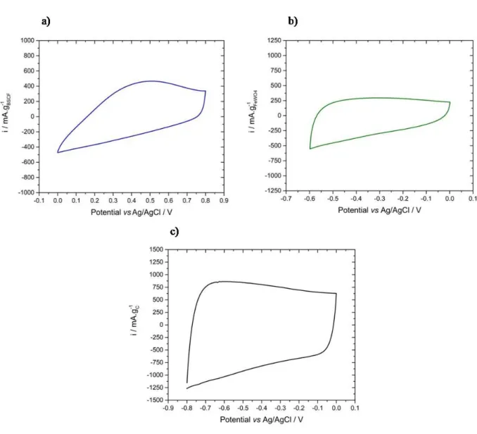
In Fig. 1 are shown the cyclic voltammograms (BSCF) and FeWOCVs) of BSCF (BSCF) and FeWO50th cycle), FeWO 4 (BSCF) and FeWO10th
cycle) and activated carbon (BSCF) and FeWO10th cycle) based electrodes, recorded in 5M LiNO
3 at 5 mV.s-δ1.
BSCF CV (BSCF) and FeWOFig. 1a) depicts a box-δtype shape characteristic of a material with a pseudocapacitive behavior, with some distortions from the typical rectangular shape. BSCF -δ based electrode is stable from 0 to 0.8 V vs Ag/AgCl and displays a specific capacitance of 57 F.g-δ1 (BSCF) and FeWO46 C.g-δ1). As such, it can be used as positive electrode material. Above 0.8 and below 0
V vs Ag/AgCl, the current increases (BSCF) and FeWOin absolute value). This is assigned to oxygen and hydrogen evolution reactions, respectively. In the present case, the 50th cycle is the cycle from
which the CV shape and the specific capacitance does not change anymore. From the 1st to the
50th cycle, an increase of the specific capacitance from 30 to 57 F.g-δ1 was observed. FeWO 4
has already been studied as negative electrode material for supercapacitors. The electrode made from FeWO4 prepared by a precipitation method is stable from -δ0.6 to 0V vs BSCFAg/AgCl
(BSCF) and FeWOFig. 1b) and displays a specific capacitance of 60 F.g-δ1 (BSCF) and FeWO36 C.g-δ1). Stable CV shape of
FeWO4 were rapidly obtained (BSCF) and FeWO10 cycles). From the 1st cycle to the 10th, only a very slight
change in specific capacitance was observed. The charge storage mechanism in FeWO4
electrode involves the Fe2+/Fe3+ redox couple. Potential below -δ0.7 V vs Ag/AgCl should be
avoided because Fe2+ is irreversibly reduced to Fe0. CV of activated carbon (BSCF) and FeWOas negative
electrode) is representative of a capacitive behavior (BSCF) and FeWOFig. 1c). This electrode can be cycled from -δ0.8 to 0 V vs Ag/AgCl. Below -δ0.8 V vs Ag/AgCl, the current increases (BSCF) and FeWOin absolute
value), which suggests that the hydrogen evolution reaction begins, causing electrolyte degradation. In this potential window, its specific capacitance is 160 F.g-δ1 (BSCF) and FeWO128 C.g-δ1) at 5
mV.s-δ1. According to these tests, two types of asymmetric devices can be built. The first one,
C/BSCF, is designed by associating a negative electrode made of activated carbon and a BSCF positive electrode. The second one is an all oxide device, with a negative electrode made of FeWO4 and a BSCF positive electrode.
Fig. 1.CVs recorded at 5 mV.s-δ1 in aqueous 5M LiNO
3 of a) BSCF based electrode (BSCF) and FeWO50th
3.3. Asymmetric devices
To keep electrode cycling in their respective potential windows, charge balance of the device has to be ensured by using an accurate weight ratio of active materials in both electrodes (BSCF) and FeWOcalculated by taking into account electrode capacities and potential windows) [39 ]. However, since each electrode material has different capabilities upon scan rate (BSCF) and FeWOor current density), this weight ratio can only be determined for a given scan rate or a given current density. In the next section, the methodology was as followed. Firstly, weight ratios were calculated to design asymmetric devices with the aim to be cycled at 5 mV.s-δ1 (BSCF) and FeWOor corresponding current
density) in 5M LiNO3 electrolyte. These specific ratios were determined using equation (BSCF) and FeWO10):
m+¿ m−¿ = C −¿ C+¿ ¿¿ ¿ ¿ (10 )
Where m+ and m-δ are the active material mass in the positive and the negative electrode
respectively and C+ and C-δ are the capacities (BSCF) and FeWOin C.g-δ1) of the positive and negative electrode
respectively.
After analysis of the results (BSCF) and FeWOcapacitances and electrochemical stability windows of electrodes), several devices with various electrode weight ratios were designed and tested by galvanostatic cycling at various current densities with the aim to find the optimal conditions allowing a good compromise between the device performances and the electrochemical stability windows of each electrodes. In this section, from one weight ratio to another, performances are not compared at the same current density, but in conditions electrodes cycle in their respective electrochemical stability window (BSCF) and FeWOi.e. BSCFin conditions a fast degradation of the device, caused by water splitting, is avoided). The conditions, in terms of electrode weight
ratios and current densities, leading to the best compromise between electrochemical stability of electrodes and performances, were used to test the longterm cycling ability and self-δ discharge behavior of the fabricated asymmetric devices.
3.3.1. Asymmetric C/BSCF devices
As mentioned in paragraph 3.2., specific capacities of BSCF and activated carbon (BSCF) and FeWOas negative electrode) in 5M LiNO3 at 5 mV.s-δ1 are 46 and 128 C.g-δ1, respectively. Thus, a theoretical
BSCF/C weight ratio of 2.8 is expected to allow the electrodes to cycle in their respective stable potential windows (BSCF) and FeWOi.e. from 0 to 0.8 V vs Ag/AgCl for BSCF and from -δ0.8 to 0 V vs Ag/AgCl for activated carbon). As such, electrode loadings used to build this device with a BSCF/C weight ratio of 2.8 were 14.2 mgBSCF.cm-δ2 and 5.0 mgC.cm-δ2.
Fig. S3 depicts C/BSCF CV from 0 to 1.6 V (BSCF) and FeWOaccording to the electrochemical window of each electrodes), together with those of activated carbon and BSCF electrodes. The CV shape of the full device is rectangular as expected for an electrochemical capacitor. However, as shown in Fig. S3, activated carbon and BSCF do not cycle in their respective electrochemical window. In such a case, potential windows of activated carbon and BSCF based electrodes are -δ1.0 – -δ0.1 V vs BSCFAg/AgCl and -δ0.1 – 0.6 V vs Ag/AgCl, respectively. As mentioned above, at -δ 1.0 V vs Ag/AgCl, water is reduced at the carbon electrode surface and loss of performance upon cycling the cell is likely to occur because of this electrolyte degradation. Actually, the same shift in the electrode potential windows was observed when using a current density ranging from 0.1 to 4 A.g-δ1 (BSCF) and FeWOof active material). As such, the BSCF/C weight ratio of 2.8 was
no longer considered for the rest of the study.
To evaluate C/BSCF performance, several devices with various BSCF/C weight ratio have then been prepared and tested. BSCF/C weight ratio were 1.5, 2.1, 2.4 and 3.6. CVs at 5 mV.s-δ
1 of the fabricated devices are reported in Fig. S4. Total mass of active material and total
volume of electrodes and current collectors used to evaluate device performance are listed in
Tab. S4 together with the capacitances and the specific capacitances. Despite a slight decrease for the weight ratio of 3.6, the greater the weight ratio, the greater the measured capacitance. In contrast, the greater electrode masses needed for the highest weight ratio strongly impacted on the corresponding specific capacitances, as the greater the weight ratio, the lower the specific capacitance. Looking closer at electrode CVs in Fig. S4, one can notice that electrodes were operated in their safe electrochemical window only for the device with a weight ratio of 1.5, i.e. between 0 and -δ0.8 V vs Ag/AgCl for activated carbon electrode and between 0 and +0.8 V vs Ag/AgCl for BSCF electrode. For the other devices, the activated carbon electrode potential window decreases down to -δ0.8 V vs Ag/AgCl (BSCF) and FeWOhence, BSCF electrode potential window does not reach + 0.8 V vs Ag/AgCl) which could lead to electrolyte degradation.
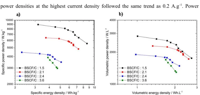
Energy and power densities of these devices have been determined from galvanostatic cycling by applying current densities ranging from 0.2 to 4 A.g-δ1 (BSCF) and FeWOtotal mass of active materials in the
cell). Specific and volumetric performance are shown in Fig. 2a and 2b, respectively, as well as the Ragone plots. The corresponding galvanostatic cycles are depicted in Fig. S5. As generally observed for electrochemical capacitors, the energy density of fabricated C/BSCF devices decreased as the applied current density increased. At low current density, i.e. 0.2 A.g-δ 1, the greater the BSCF/C weight ratio, the lower the energy and the power densities (BSCF) and FeWOboth
specific and volumetric). This behavior was assigned to both lower capacitances and greater electrode masses and volumes as the BSCF/C weight ratio increased. At 0.2 A.g-δ1, the
C/BSCF device with a weight ratio of 1.5 presented the greatest energy densities in the series at 8.6 Wh.kg-δ1 and 2.7 Wh.L-δ1. A similar trend was observed for power densities. At 0.2 A.g-δ1,
BSCF/C weight ratio. With the increase of the current density at 4 A.g-δ1, the C/BSCF device
with a weight ratio of 2.1 showed the greatest energy densities with 3.7 Wh.kg-δ1 and 1.3
Wh.L-δ1. Compared to the device with a 1.5 weight ratio, this energy density improvement
originated from a greater capacitance (BSCF) and FeWO37 mF for a ratio of 2.1 vs 27 mF for a ratio of 1.5) which allowed to compensate for the larger mass and volume of the electrodes. However, power densities at the highest current density followed the same trend as 0.2 A.g-δ1. Power
densities decreased from 8.9 to 4.4 Wh.kg-δ1 and from 2.8 to 1.9 Wh.L-δ1 when the weight ratio
increases.
Fig. 2. Ragone plots representing the evolution of the power density vs the energy density of
the four C/BSCF devices tested in 5M LiNO3 with BSCF/C ratios of 1.5 (BSCF) and FeWOblack), 2.1 (BSCF) and FeWOred), 2.4
(BSCF) and FeWOblue) and 3.6 (BSCF) and FeWOgreen). Current densities applied are 0.2, 0.5, 0.6, 0.8, 1.0, 1.2, 2.0 and 4 A.g-δ1.
Graph a) specific power and energy densities and b) volumetric power and energy densities; gravimetric values are expressed per total active weights in both electrodes and volumetric values per volume of both electrodes and their current collector. Calculations have been done using Eqs (BSCF) and FeWO9) and (BSCF) and FeWO10).
In the whole range of applied current densities, only a single current density applied for each C/BSCF device allows to operate BSCF and C electrodes in their safe electrochemical window. These are 0.2, 0.5, 0.5 and 1.2 A.g-δ1 for C/BSCF devices with weight ratio of 1.5,
activated carbon and BSCF electrodes at such optimized current densities are -δ0.8 – 0 V vs Ag/AgCl and 0 – 0.8 V vs Ag/AgCl, respectively, corresponding to targeted electrochemical stability windows of both electrodes. For lower current densities, activated carbon electrode potential goes below -δ0.8 V vs Ag/AgCl and for higher current densities, BSCF electrode potential rises to 0.8 V vs Ag/AgCl and above. According to Tab. 1, increasing the BSCF/C weight ratio allows to reach greater charge and discharge rates. To fabricate the most performing C/BSCF device, a BSCF/C weight ratio of 1.5 and a 0.2 A.g-δ1 current density
should be considered. However, in these conditions, a large discrepancy between charge and discharge times is observed. To avoid this unbalanced characteristic, the device with a weight ratio of 2.1 operated at a current density of 0.5 A.g-δ1 was selected for further tests. To move a
step forward in the device characterization, self-δdischarge measurements and cycling ability tests were performed on a C/BSCF device with a weight ratio of 2.1 at 0.5 A.g-δ1, and are
presented in section 3.3.3.
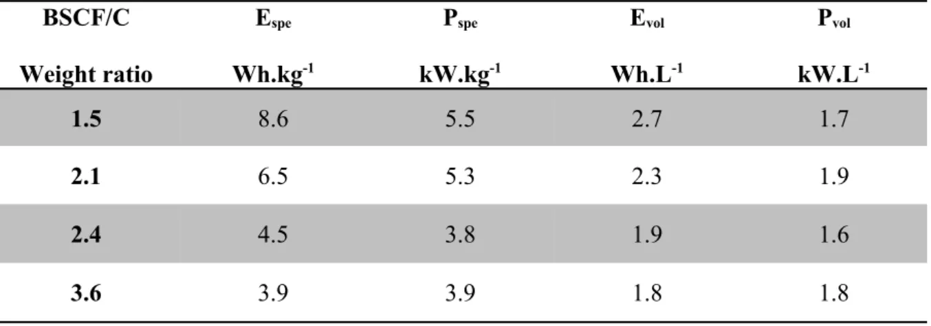
Tab. 1.Specific energy and power densities (BSCF) and FeWOEspe and Pspe), volumetric energy and power
densities (BSCF) and FeWOEvol and Pvol) of C/BSCF full devices with BSCF/C weight ratio of 1.5, 2.1, 2.4 and
3.6 recorded in 5M LiNO3 at 0.2, 0.5, 0.5 and 1.2 A.g-δ1, respectively; gravimetric values are
expressed per total active weights in both electrodes and volumetric values per volume of both electrodes and their current collector.
BSCF/C Weight ratio Espe Wh.kg-1 Pspe kW.kg-1 Evol Wh.L-1 Pvol kW.L-1 1.5 8.6 5.5 2.7 1.7 2.1 6.5 5.3 2.3 1.9 2.4 4.5 3.8 1.9 1.6 3.6 3.9 3.9 1.8 1.8
3.3.2. Asymmetric FeWO4/BSCF devices
The study on all oxide asymmetric FeWO4/BSCF devices followed the same methodology as
for C/BSCF devices. According to specific capacities measured for FeWO4 and BSCF
electrodes, respectively 36 and 46 C.g-δ1 at 5 mV.s-δ1 in 5M LiNO
3, a FeWO4/BSCF weight ratio
of 0.8 should lead to suitable potential windows for both electrodes. Alternatively, two other devices with FeWO4/BSCF weight ratio at 1.67 and 2 were tested. These devices have been
cycled between 0 and 1.4 V.
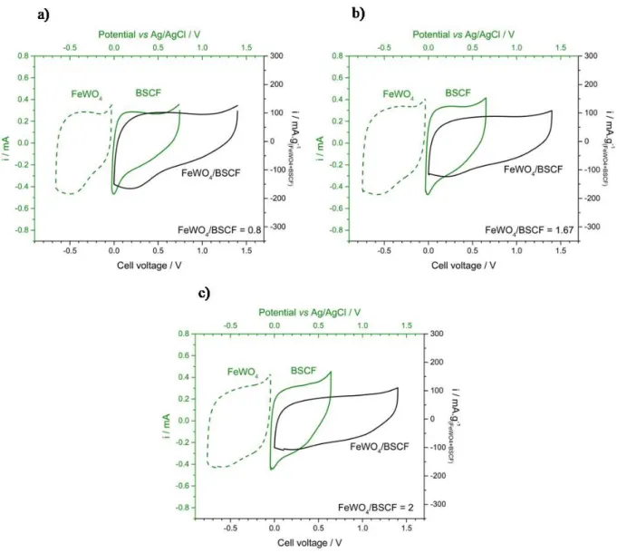
CVs of the various FeWO4/BSCF device, together with those of their electrodes, are shown in
Fig. 3. Total active material mass, total volume of electrodes and current collectors, capacitances and specific capacitances of fabricated devices are listed in Tab. S5. As for C/BSCF devices, the CV of FeWO4/BSCF device shows a distorted rectangular shape,
characteristic of a pseudocapacitive behavior. From FeWO4/BSCF weight ratio at 0.8 to 2,
specific capacitances are found to remain the same, close to 16-δ17 F.g-δ1. The potential window
of BSCF electrode, ranging approximately from 0 – 0.7 V vs Ag/AgCl, was fitting in its electrochemical stability window (BSCF) and FeWO0 – 0.8 V vs Ag/AgCl). However, the potential window of FeWO4 electrodes ranged approximately from -δ0.7 – 0 V vs Ag/AgCl. This potential window
could result in a fade of performance upon cycling since, at the lowest limit, the electrode potential is very close to that of the irreversible Fe2+ → Fe0 reduction reaction.
Fig. 3.CVs recorded at 5 mV.s-δ1 in 5M LiNO
3 of FeWO4/BSCF devices (BSCF) and FeWOblack line) together
with FeWO4 (BSCF) and FeWOgreen dots) and BSCF electrodes (BSCF) and FeWOgreen line) CVs with BSCF/FeWO4 weight
ratio of a) 0.8, b) 1.67 and c) 2; gravimetric values are expressed per active weight in both electrodes.
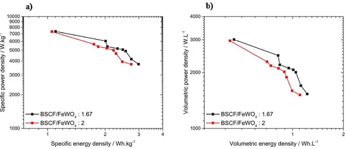
To optimize the operating conditions for FeWO4/BSCF devices and to evaluate their
performance, galvanostatic cycling was performed at various current densities from 0.25 to 4 A.g-δ1. Specific and volumetric densities are reported in Fig. 4 and the galvanostatic cycles are
depicted in Fig. S7. Performance of the FeWO4/BSCF device with a weight ratio of 0.8 are
not reported because, whatever the applied current density, the FeWO4 electrode potential
always reached potentials below -δ0.7 V vs Ag/AgCl. As such, poor coulombic efficiencies at 42 (BSCF) and FeWOat 0.25 A.g-δ1) and 92 %(BSCF) and FeWOat 4 A.g-δ1) were obtained, demonstrating the limited reversibility
of charge and discharge processes that could originate from an irreversible reduction of Fe2+
to Fe0. As for C/BSCF devices, when the current density was greater, the corresponding
energy density of FeWO4/BSCF devices decreased, either with FeWO4/BSCF weight ratio at
1.67 or 2. Specific and volumetric performance of the tested FeWO4/BSCF devices were
approximately the same but energy densities of the device with a weight ratio of 2 were slightly weaker. At 0.25 A.g-δ1, energy densities of FeWO
4/BSCF devices with a ratio of 1.67
and 2 were 2.9 and 2.7 Wh.kg-δ1 respectively, and 1.2 and 1.1 Wh.L-δ1 respectively. At the same
current density, power densities for both devices were similar at about 3.8 kW.kg-δ1 and 1.5
kW.L-δ1. When the current density is increased to 4 A.g-δ1, energy densities of the devices with a
ratio of 1.67 and 2 decreased to 1.1 and 1.0 Wh.kg-δ1, respectively and to 0.5 and 0.4 Wh.L-δ1,
respectively. With these asymmetric devices, the limit of the FeWO4 electrode potential
window was lower than the expected value at -δ0.6 V vs Ag/AgCl. For each devices, a single current density allowed to limit the FeWO4 electrode potential above -δ0.7 V vs Ag/AgCl, thus
limiting the Fe2+ reduction to Fe0. These current densities are 0.4 and 0.25 A.g-δ1 of active
material for FeWO4/BSCF devices with weight ratio of 1.67 and 2, respectively
(BSCF) and FeWOcorresponding galvanostatic cycles are in Fig. S8). At such current densities, the devices showed the same energy densities of 2.7 Wh.kg-δ1 and 1.1 Wh.L-δ1. The FeWO
4/BSCF cycling
ability and self-δdischarge behavior were further evaluated on the device with a FeWO4/BSCF
Fig. 4.Ragone plots representing the evolution of the power density vs the energy density of
the two FeWO4/BSCF devices tested in 5M LiNO3 with BSCF/FeWO4 ratio of 1.67 (BSCF) and FeWOblack)
and 2 (BSCF) and FeWOred). Current densities applied are 0.25, 0.4, 0.5, 0.6, 0.8, 1, 1.2 and 4 A.g-δ1. Graph a)
represents specific power and energy densities and b) represents volumetric power and energy densities; gravimetric values are expressed per total active weights in both electrodes and volumetric values per volume of both electrodes and their current collector. Calculations have been done using Eqs (BSCF) and FeWO9) and (BSCF) and FeWO10).
3.3.3. Cycling ability and self-δdischarge behavior of C/BSCF and FeWO4/BSCF asymmetric
devices
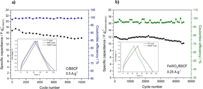
Cycling ability of C/BSCF (BSCF) and FeWOBSCF/C weight ratio of 2.1) and FeWO4/BSCF (BSCF) and FeWOFeWO4/BSCF
weight ratio of 2) devices were evaluated in 5M LiNO3 at 0.5 and 0.25 A.g-δ1, respectively. The
current densities were chosen according to balance the potential window of their electrodes. Evolutions of the specific capacitance of these devices vs number of cycles are depicted in
Fig. 5. The specific capacitance of the C/BSCF device was 17 F.g-δ1 at the beginning of the
cycling test, as shown in Fig. 5a. First, the specific capacitance increases which is due to BSCF electrode activation. Then, it progressively decreased down to 15 F.g-δ1 for the 10,000th
cycle for an overall 12 % fading. This capacitance fading of the device could be due to the BSCF electrode behavior, as it showed a specific capacitance fading of approximately 10% over 2,000 cycles [30 ], whereas activated carbon electrodes are known to be stable over
hundred thousands of cycles, eventually. Furthermore, coulombic efficiency of the device was above 98 % over the entire cycling test, demonstrating the good charge/discharge reversibility of the device. To go further, impedance spectroscopy was performed after the 10th and the last
cycle of the long term cycling test. Corresponding Nyquist diagrams are shown in Fig. S9a. The resistance measured at high frequencies, at the intercept between the EIS plot and the Z’ axis, corresponds to the resistance of the separators impregnated by the electrolyte. This resistance is approximately 1 Ω) obtained by ohmic drop measurement during after the 10th cycle and does not seem to further increase after
the 10,000th cycle. At lower frequencies a semi-δcircle can be observed. It is usually assigned
to the interface resistance between the active material and current collector [40 ]. This charge transfer resistance (BSCF) and FeWO0.8 Ω) obtained by ohmic drop measurement during) showed limited changes upon cycling. It only increased up to 1 Ω) obtained by ohmic drop measurement during from the 10th to the 10,000th cycle. The equivalent series resistance evaluated at high
frequency was 2.7 Ω) obtained by ohmic drop measurement during after 10 cycles and increased at 3 Ω) obtained by ohmic drop measurement during after 10,000 cycles. The limited changes upon cycling of the various resistances measured demonstrate the high stability of the device.
Cycling ability of the FeWO4/BSCF device has been evaluated over 45,000 cycles. The
choice to apply for a greater number of cycles for this specific device was motivated by the opportunity to evaluate the cycling ability of an all-δoxide device as only a few studies depict such performance over such a large number of cycles. Changes in the specific capacitance of the FeWO4/BSCF device upon charge/discharge cycling at 0.25 A.g-δ1 is shown in Fig. 5b. Its
initial specific capacitance at 12 F.g-δ1 goes down to 10 F.g-δ1 at the end of the cycling test,
corresponding to an overall 17% fading of the specific capacitance after 45,000 cycles. In comparison with the C/BSCF device, operated at 0.5 A.g-δ1, the specific capacitance fading of
the FeWO4/BSCF device is limited to about 3% after the 10,000th cycle, demonstrating the
remarkable cycling ability of this device, especially when operated at a moderate current density of 0.25 A.g-δ1. As it can be observed on this graph, the capacitance fading is more
pronounced after 22,000 cycles. This behavior is not necessarily assigned to the electrodes but to a non-δoptimized setup. The Coulombic efficiency of this device upon the entire cycling test is about 95%, lower than for C/BSCF or what is generally observed in electrochemical capacitors (BSCF) and FeWO98-δ99%). This can be due to some parasitic Fe2+ reduction reaction to Fe0 because
of a potential limit of FeWO4 electrode close to -δ0.7 V vs Ag/AgCl. Nyquist diagrams after 10
cycles and 45,000 cycles are depicted in Fig. S9b. The resistance measured at high frequencies increased from 1.3 to 1.7 Ω) obtained by ohmic drop measurement during after the 45,000th cycle. The semi-δcircle assigned to
the charge transfer resistance is not clearly defined after 45,000 cycles, but, it is clear that this resistance was increased upon cycling. Finally, the equivalent series resistance also increased during cycling, from 7.4 to 18.3 Ω) obtained by ohmic drop measurement during.
In the literature, only a few studies deal with long term stability evaluation of symmetric or asymmetric aqueous devices with at least one pseudocapacitive oxide. Among them, asymmetric devices were reported with a negative activated carbon electrode such as C/BiMn2O5 [41 ] and C/MnO2 [42 ]. The first one presented only a 90% retention of its
capacitance over 1,000 cycles (BSCF) and FeWO10 mA.cm-δ2, 1.8 V, 0.5M Na
2SO4). On the other hand, the
C/MnO2 device presented the greatest cycling ability ever reported in the literature with a
87.5% of retention over 195,000 cycles (BSCF) and FeWO40 mA.cm-δ2, 2 V, 0.1M Kα radiation, from 10 to 90°
2SO4). Some symmetric
devices have also been tested, such as ZnFe2O4/ZnFe2O4 (BSCF) and FeWOcomposite electrodes with carbon
nanotubes) which maintained only 70 % of its capacitance over 2,000 cycles (BSCF) and FeWO0.9 V, 1M LiCl)
[43 ]. Finally, a few studies on asymmetric devices free of activated carbon have been reported. For example, VN/MnO2 (BSCF) and FeWOcomposite electrodes with carbon nanotubes) retained only
80% of its initial capacitance over 1,000 cycles (BSCF) and FeWO10 mA, 1.8 V, 0.5M Na2SO4) [44 ]. The first
asymmetric device with two oxides ever reported, Fe3O4/MnO2, presented also a limited
cycling ability with a 50% capacitance fading over 5,000 cycles (BSCF) and FeWO1.8 V, 0.1M Kα radiation, from 10 to 90°2SO4) [45 ]. As
cycles (BSCF) and FeWO20 mV.s-δ1, 1.6 V, 5M LiNO
3) [31 ]. As MnO2 electrode has demonstrated a fair cycling
stability, the greater cycling ability of the FeWO4/MnO2 device when compared to that of
Fe3O4/MnO2 device was assigned to the stability of the Fe2+/Fe3+ redox couple in the FeWO4
structure. Initial C/BSCF device capacitance faded down by 12% over 10,000 cycles (BSCF) and FeWO0.5 A.g-δ 1, 1.6 V, 5M LiNO
3) while it was 17% fading for the FeWO4/BSCF device over 45,000 cycles
(BSCF) and FeWO0.25 A.g-δ1, 1.4 V, 5M LiNO
3). This cycling ability, similar to that of FeWO4/MnO2,
originates from the good cycling stability of individual electrodes.
Fig. 5.Cycling ability test performed on a) C/BSCF device with a BSCF/C ratio of 2.1 at 0.5
A.g-δ1 in 5M LiNO
3 (BSCF) and FeWOevolution of the specific capacitance in black and coulombic efficiency in
blue) and b) FeWO4/BSCF device with a BSCF/FeWO4 weight ratio of 2 at 0.25 A.g-δ1 in 5M
LiNO3 (BSCF) and FeWOevolution of the specific capacitance in black and coulombic efficiency in green).
Insets are galvanostatic cycles after various cycles; gravimetric values are expressed per total active weights in both electrodes.
Self-δdischarge behavior has been evaluated for C/BSCF (BSCF) and FeWOBSCF/C weight ratio of 2.1) and FeWO4/BSCF (BSCF) and FeWOFeWO4/BSCF weight ratio of 2) devices and compared to that of a symmetric
C/C device (BSCF) and FeWOcell voltage 1.6 V). The activated carbon used for the symmetric device is the same as for the C/BSCF device. C/C, C/BSCF and FeWO4/BSCF cells have been fully
respectively. The corresponding total charges stored Qmax are 252, 67 and 44 mC, respectively.
The self-δdischarge profile (BSCF) and FeWOplot vs the time) measured after a 3 hours polarization at maximum cell voltage is shown in Fig. 6. Half of the cell voltage (BSCF) and FeWOi.e. when half of totals charges stored are released) was reached in 10 and 47 hours respectively for the C/BSCF and FeWO4/BSCF
devices. Self-δdischarge currents of C/BSCF and FeWO4/BSCF are 9 and 4 µA.F-δ1,
respectively (BSCF) and FeWOcalculations to determine self-δdischarge current are described in SI). This is respectively 6 and 14 times lower than the self-δdischarge current of the C/C device which is 57 µA.F-δ1 (BSCF) and FeWOwith half of the cell voltage reached in only 4 hours). Despite a lower cycling
ability, asymmetric C/BSCF and FeWO4/BSCF devices demonstrate improved self-δdischarge
characteristics compared to the symmetric C/C device. A detailed analysis of the self-δ discharge profiles is provided in SI (BSCF) and FeWOFig. S10 and Tab. S6).
Fig. 6.Self-δ discharge
profile of C/C, C/BSCF and FeWO4/BSCF devices.
4. Conclusion
We report for the first time, two asymmetric electrochemical capacitors based on BSCF positive electrode material. The first one includes an activated carbon based negative
electrode. The second, a FeWO4-δbased negative electrode, leading to a device with two high
density multicationic oxides as electrode materials. The high densities of both oxides, together with the low capacitances of the electrodes led to lower specific performance than those of a symmetrical C/C device. However, the high densities of BSCF and FeWO4 enable electrodes
of smaller volume. On one hand, the small volume of electrodes was not sufficient to compensate the limited capacitance of the FeWO4/BSCF device. On the other hand, the high
density of BSCF, associated to the high capacitance of activated carbon electrode led to similar volumetric energy density as for the C/C devices, despite a limited capacitance. At low current density (BSCF) and FeWO0.2-δ0.4 A.g-δ1), the C/BSCF device volumetric energy density was even
greater than that of the C/C device, at 2.3 Wh.L-δ1 (BSCF) and FeWOrelative to the volume of electrodes and
current collectors). Furthermore, both devices presented attractive cycling abilities upon cycling with a capacitance retention of 88% over 10,000 cycles for the C/BSCF device and 83% over 45,000 cycles for the FeWO4/BSCF device. It is important to notice that such a long
cycling test of an asymmetric device built on two pseudocapacitive oxides is scarce in the literature. Furthermore, asymmetric devices present better self-δdischarge characteristics than the C/C device. Asymmetric devices built on two pseudocapacitive multicationic oxides could be an attractive strategy to improve the volumetric energy density of electrochemical capacitors. However, in aqueous based electrolytes, large specific capacitances are mandatory to compete with symmetric C/C devices, at least 100 F.g-δ1.
This work was supported by the French National Agency through IVEDS project -δ Improving the Volumetric Energy Density of Supercapacitors – ref ANR-δ15-δCE05-δ0011.
Notes
The authors declare no competing financial interest
References
1 Conway, B. E. Electrochemical Supercapacitors: Scientific Fundamentals and Technological Applications. Kluwer Academic/Plenum Publishers (1999).
2 Long, J. W. et al. Asymmetric electrochemical capacitors—Stretching the limits of aqueous electrolytes. MRS Bulletin 36, 513-522 (2011).
3 Brousse, T., Bélanger, D. & Long, J. W. To Be or Not To Be Pseudocapacitive? Journal of The Electrochemical Society 162, A5185-A5189 (2015).
4 Trasatti, S. & Buzzanca, G. Ruthenium dioxide: A new interesting electrode material. Solid state structure and electrochemical behaviour. Journal of Electroanalytical Chemistry and Interfacial Electrochemistry 29, A1-A5 (1971).
5 Zheng, J. P., Cygan, P. J. & Jow, T. R. Hydrous Ruthenium Oxide as an Electrode Material for Electrochemical Capacitors. Journal of The Electrochemical Society 142, 2699-2703 (1995).
6 Hu, C.-C., Chen, W.-C. & Chang , K.-H. How to Achieve Maximum Utilization of Hydrous Ruthenium Oxide for Supercapacitors. Journal of The Electrochemical Society 151, A281-A290 (2004).
7 Lee, H. Y. & Goodenough, J. B. Supercapacitor Behavior with KCl Electrolyte. Journal of Solid State Chemistry 144, 220-223 (1999).
8 Toupin, M., Brousse, T. & Bélanger, D. Charge Storage Mechanism of MnO2
Electrode Used in Aqueous Electrochemical Capacitor. Chemistry of Materials 16, 3184-3190 (2004).
9 Ghodbane, O., Pascal, J.-L. & Favier, F. Microstructural Effects on Charge-Storage Properties in MnO2-Based Electrochemical Supercapacitors. ACS
Applied Materials & Interfaces 1, 1130-1139 (2009).
10 Cottineau, T., Toupin, M., Delahaye, T., Brousse, T. & Bélanger, D. Nanostructured transition metal oxides for aqueous hybrid electrochemical supercapacitors. Applied Physics A 82, 599-606 (2006).
11 Wu, N.-L., Wang, S.-Y., Han, C.-Y., Wu, D.-S. & Shiue, L.-R. Electrochemical capacitor of magnetite in aqueous electrolytes. Journal of Power Sources 113, 173-178 (2003).
12 Choi, D., Blomgren, G. E. & Kumta, P. N. Fast and Reversible Surface Redox Reaction in Nanocrystalline Vanadium Nitride Supercapacitors. Advanced Materials 18, 1178-1182 (2006).
13 Lucio-Porto, R. et al. VN thin films as electrode materials for electrochemical capacitors. Electrochimica Acta 141, 203-211 (2014). 14 Liu, T. C., Pell, W. G., Conway, B. E. & Roberson, S. L. Behavior of
Molybdenum Nitrides as Materials for Electrochemical Capacitors: Comparison with Ruthenium Oxide. Journal of The Electrochemical Society 145, 1882-1888 (1998).
15 Shown, I., Ganguly, A., Chen, L.-C. & Chen, K.-H. Conducting polymer-based flexible supercapacitor. Energy Science & Engineering 3, 2-26 (2015).
16 Boota, M. et al. Pseudocapacitive Electrodes Produced by Oxidant-Free Polymerization of Pyrrole between the Layers of 2D Titanium Carbide (MXene). Advanced Materials 28, 1517-1522 (2016).
17 Goubard-Bretesché, N., Crosnier, O., Favier, F. & Brousse, T. Improving the Volumetric Energy Density of Supercapacitors. Electrochimica Acta 206, 458-463 (2016).
18 Crosnier, O. et al. Polycationic oxides as potential electrode materials for aqueous-based electrochemical capacitors. Current Opinion in Electrochemistry 9, 87-94 (2018).
19 Mefford, J. T., Hardin, W. G., Dai, S., Johnston, K. P. & Stevenson, K. J. Anion charge storage through oxygen intercalation in LaMnO3 perovskite
pseudocapacitor electrodes. Nature Materials 13, 726 (2014).
20 Hwang, D. K., Kim, S., Lee, J.-H., Hwang, I.-S. & Kim, I.-D. Phase evolution of perovskite LaNiO3 nanofibers for supercapacitor application and p-type gas
sensing properties of LaOCl–NiO composite nanofibers. Journal of Materials Chemistry 21, 1959-1965 (2011).
21 Cao, Y., Lin, B., Sun, Y., Yang, H. & Zhang, X. Symmetric/Asymmetric Supercapacitor Based on the Perovskite-type Lanthanum Cobaltate Nanofibers with Sr-substitution. Electrochimica Acta 178, 398-406 (2015). 22 Lü, J. et al. A preliminary study of the pseudo-capacitance features of
strontium doped lanthanum manganite. RSC Advances 5, 5858-5862 (2015).
23 Cao, Y., Lin, B., Sun, Y., Yang, H. & Zhang, X. Sr-doped Lanthanum Nickelate Nanofibers for High Energy Density Supercapacitors. Electrochimica Acta 174, 41-50 (2015).
24 Abdollahifar, M. et al. High-performance carbon-coated ZnMn2O4
nanocrystallite supercapacitors with tailored microstructures enabled by a novel solution combustion method. Journal of Power Sources 378, 90-97 (2018).
25 Kuo, S.-L., Lee, J.-F. & Wu, N.-L. Study on Pseudocapacitance Mechanism of Aqueous MnFe2O4 Supercapacitor. Journal of The Electrochemical Society
154, A34-A38 (2007).
26 Kuo, S.-L. & Wu, N.-L. Electrochemical characterization on MnFe2O4/carbon
black composite aqueous supercapacitors. Journal of Power Sources 162, 1437-1443 (2006).
27 Chang, S.-K. et al. Structural and electrochemical properties of manganese substituted nickel cobaltite for supercapacitor application. Electrochimica Acta 67, 67-72 (2012).
28 Goubard-Bretesché, N., Crosnier, O., Payen, C., Favier, F. & Brousse, T. Nanocrystalline FeWO4 as a pseudocapacitive electrode material for high
volumetric energy density supercapacitors operated in an aqueous electrolyte. Electrochemistry Communications 57, 61-64 (2015).
29 Shanmugavani, A., Murugeswari, R., Sanjeeviraja, C. & Selvan, R. K. Nanocrystalline Pyrochlore La2Sn1.6Zr0.4O7 as a New Candidate for
Supercapacitor Electrodes. Journal of Nanoscience and Nanotechnology 15, 2790-2797 (2015).
30 Lannelongue, P. et al. Investigation of Ba0.5Sr0.5CoxFe1-xO3-δ as a
pseudocapacitive electrode material with high volumetric capacitance. Electrochimica Acta 271, 677-684 (2018).
31 Goubard-Bretesché, N., Crosnier, O., Buvat, G., Favier, F. & Brousse, T. Electrochemical study of aqueous asymmetric FeWO4/MnO2 supercapacitor.
Journal of Power Sources 326, 695-701 (2016).
32 Liu, P. et al. Ba0.5Sr0.5Co0.8Fe0.2O3-δ-based dual-gradient cathodes for solid
oxide fuel cells. Ceramics International 44, 4516-4519 (2018).
33 Cheng, X., Fabbri, E., Kim, B., Nachtegaal, M. & Schmidt, T. J. Effect of ball milling on the electrocatalytic activity of Ba0.5Sr0.5Co0.8Fe0.2O3 towards the
oxygen evolution reaction. Journal of Materials Chemistry A 5, 13130-13137 (2017).
34 Habiballah, A. S., Jani, A. M. M., Mahmud, A. H., Osman, N. & Radiman, S. Facile synthesis of Ba0.5Sr0.5Co0.8Fe0.2O3-δ (BSCF) perovskite nanowires by
templating from nanoporous anodic aluminium oxide membranes. Materials Chemistry and Physics 177, 371-378 (2016).
35 Tan, L. A. et al. Influence of powder synthesis methods on microstructure and oxygen permeation performance of Ba0.5Sr0.5Co0.8Fe0.2O3-δ
perovskite-type membranes. Journal of Membrane Science 212, 157-165 (2003). 36 Wang, H. H., Tablet, C., Feldhoff, A. & Caro, H. Investigation of phase
structure, sintering, and permeability of perovskite-type Ba0.5Sr0.5Co0.8Fe0.2O3-δ membranes. Journal of Membrane Science 262, 20-26
(2005).
37 Kovács, T. N. et al. Preparation of iron tungstate (FeWO4) nanosheets by
hydrothermal method. Materials Research Bulletin 95, 563-569 (2017). 38 Niu, L. et al. Simple Synthesis of Amorphous NiWO4 Nanostructure and Its
Application as a Novel Cathode Material for Asymmetric Supercapacitors. ACS Applied Materials & Interfaces 5, 8044-8052 (2013).
39 Balducci, A., Belanger, D., Brousse, T., Long, J. W. & Sugimoto, W. Perspective—A Guideline for Reporting Performance Metrics with Electrochemical Capacitors: From Electrode Materials to Full Devices. Journal of The Electrochemical Society 164, A1487-A1488 (2017).
40 Soeda, K., Yamagata, M. & Ishikawa, M. Outstanding features of alginate-based gel electrolyte with ionic liquid for electric double layer capacitors. Journal of Power Sources 280, 565-572 (2015).
41 Liu, Y. & Zhitomirsky, I. Electrochemical supercapacitor based on multiferroic BiMn2O5. Journal of Power Sources 284, 377-382 (2015).
42 Brousse, T. et al. Long-term cycling behavior of asymmetric activated carbon/MnO2 aqueous electrochemical supercapacitor. Journal of Power
Sources 173, 633-641 (2007).
43 Raut, S. S. et al. Zinc Ferrite Anchored Multiwalled Carbon Nanotubes for High-Performance Supercapacitor Applications. European Journal of Inorganic Chemistry 2018, 137-142 (2018).
44 Su, Y. & Zhitomirsky, I. Hybrid MnO2/carbon nanotube-VN/carbon nanotube
supercapacitors. Journal of Power Sources 267, 235-242 (2014).
45 Brousse, T. & Bélanger, D. A Hybrid Fe3O4 /MnO2 Capacitor in Mild Aqueous