Science Arts & Métiers (SAM)
is an open access repository that collects the work of Arts et Métiers Institute of Technology researchers and makes it freely available over the web where possible.
This is an author-deposited version published in: https://sam.ensam.eu Handle ID: .http://hdl.handle.net/10985/10252
To cite this version :
Pierre-Olivier LOGERAIS, Raouf KHELALFA, Olivier RIOU, Jean-Félix DURASTANTI, Anne BOUTEVILLE - Influence of the window thermal diffusivity on the silicon wafer temperature in a rapid thermal system - Heat Transfer Engineering - Vol. 36, n°13, p.1111-1121 - 2015
Logerais et al. in Heat Transfer Engineering, 36(13) (2015) 1111-1121
Influence of the windo thermal diffusivity on the silicon wafer
temperature in a rapid thermal system
Pierre-Olivier LOGERAIS1, Raouf KHELALFA1, Olivier RIOU1, Jean-Félix DURASTANTI1, Anne BOUTEVILLE2
1 CERTES, Université Paris-Est, IUT de Sénart, Lieusaint, France 2
LAMPA, Arts et Métiers ParisTech, Angers, France
ABSTRACT
The heating of a silicon wafer in a rapid thermal process is studied by numerical simulation. In the model, the equations of conservation of mass and energy are solved with the finite volume method and the determination of the solutions of the radiative transfer equation is based on the Monte-Carlo method. The results of numerical simulations, without optimization and in steady-state, show a close relationship between the thermal profiles of the silicon wafer and the ones of the quartz window. By introducing a high thermal diffusivity value for the window, the homogeneity of the wafer temperature is improved by 54%. The effect of heat storage by the quartz window on the temperature profile of the silicon substrate is hence well appreciated. Finally, a selection of materials is proposed for the implementation of the high diffusivity infrared window.
Address correspondence to Dr. Pierre-Olivier Logerais, Université Paris-Est Créteil (UPEC), IUT de Sénart – Fontainebleau, Département Génie Industriel et Maintenance (GIM), Rue Georges Charpak, 77567 Lieusaint Cedex, France
Email : pierre-olivier.logerais@u-pec.fr
INTRODUCTION
Rapid thermal processes (RTP) are widely used in the manufacturing of microelectronic components. They are implemented in key stages as annealing for ion diffusion, silicidation, oxidation, nitridation and more recently for thin film deposition [1]. Since the introduction of the first integrated circuits, the silicon technology is constantly striving to miniaturize semiconductor components to improve circuit performance. In the 1980s, the use of conventional furnaces started becoming an impediment to the miniaturization of microelectronic components because of their high inertia. To ensure thermal treatments of small durations, rapid thermal processes have emerged with heating provided by infrared lamps and with a reactor wall often maintained at low temperature. Nevertheless, the main challenge is to obtain a uniform temperature over the entire surface of the silicon wafer [2,3]. Although a significant improvement has been achieved since the inception of the process, this condition is indeed a major issue. It is indeed necessary to provide an identical treatment over the entire surface of the wafer so that the components satisfy the required quality criteria. The study of the heating of the silicon wafer by numerical simulation enables to understand better the phenomena responsible for the observed temperature gradients [4-6]. Intuition and experience had been the only tools for many years. The present study utilizes the simulation approach to grasp better the relationship between the heating of infrared lamps and the thermal profile of the silicon substrate. In order to do it, a validated rapid thermal system model is considered [7]. The results of the first simulations have demonstrated that the differences in temperature of the quartz window have an influence on the temperature homogeneity of the silicon wafer [8,9]. We attempt in this study to explain the influence of the quartz window by reflecting on its thermal properties and their influence on the temperature distribution of the silicon wafer.
MODELING
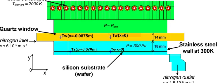
The simulated rapid thermal system (figure 1) is of type AS-One 150 marketed by the company AnnealSys (Montpellier, France) [10]. It consists of a bank of eighteen infrared halogen lamps. The radiation they emit is mainly in the infrared wavelengths ranging from 0.3 to 4 µm centered around 1 µm. A quartz window seals the reactor at its top while transmitting the infrared radiation emitted by the lamps. The reactor is of cylindrical shape with a stainless steel wall in which a silicon substrate of 150 mm diameter (6 inches) reposes on three quartz pins. A water flow maintains the wall at a relatively low temperature of 300 K. A pumping system is operated to ensure low pressure in the reactor and a panel to control the gas inlet and outlet.
Logerais et al. in Heat Transfer Engineering, 36(13) (2015) 1111-1121 nitrogen inlet v ≈ 6 10-5m.s-1 Infrared lamps Quartz window Stainless steel wall at 300K nitrogen outlet v ≈ 1.5 10-6m.s-1 silicon substrate (wafer) Tw(x=-0.0875m) Tw(x=0) P = 300 Pa Tfilament= 2000 K 18 mm 14 mm P ≈ Patm 0 x y
Figure 1 Model of the rapid thermal equipement AS-One 150.
The rapid thermal system is modeled (figure 1) in the case of annealing without flow of reactive gases. The reactor contains nitrogen at 300 Pa. Conservation equations are integrated over each control volume cell of the domain [11]. They enable to simulate numerically the flow (nitrogen in the reactor and lamps, air in the furnace) and the heat transfer, especially the radiative one. Flows are governed by the mass conservation of fluid:
ρV 0 div t ρ (1) and by the Navier-Stokes equation which can be written by projection onto the x-axis:
x M S u grad μ div x p u V ρ div t u ρ (2) The conservation equation of total enthalpy is solved:
h yy xy yx xx 0 0 S y τ v x τ v y τ u x τ u t p T grad . k div h V ρ div t h ρ (3) where h0 designates the mass enthalpy:
2 2
0 u v 2 1 ρ p i h (4)The radiative transfer equation is in steady-state [12]:
I(r, ). ( ' )d ' π 4 σ ) r ( I κ ) , r ( I σ κ ) , r ( I grad . π 4 ' b Ω Φ Ω Ω Ω Ω Ω Ω Ω
(5) where Φ is the phase function of the energy transfer from the incoming direction Ω’ to theoutgoing one Ω and, the radiative intensity I(r, Ω) at the surface is:
' d ) ' , r ( I ' . n π ρ ) r ( I ε ) , r ( I ' . n b Ω Ω Ω Ω Ω
(6)For a medium that emits, absorbs and diffuses, the solving of equation (5) is realized by knowing the optical properties of surfaces [13,14] and by using the Monte-Carlo method [12,15]. To simulate a solution of equation (5), the fate of rays emitted by each surface within the system is followed. These emitted rays are traced until they are absorbed by the same or by some other surface. Each piece of surface is called "patch" and hence the radiative energy is exchanged by emission or absorption of radiations between patches. Radiative heat flux for a patch i is the result of the incident radiation from all the other patches j and of the one of its own emission. The discrete solution is then expressed as:
j 4 j N 1 j j ij ij i i i q A M δ ε σT A Q S
(7)The radiative heat flux Qi is determined for each internal surface and its value is injected in the source term Sh of heat conservation equation (3). Hence, the absorbed and emitted
radiative heat is taken into account when solving with the finite volume method, equation (3) for adjacent control volumes.
A bundle of photons emitted from a patch i undergoes several events before being absorbed by a surface: absorption, reflection (diffuse, specular or partially specular) and transmission. Each of these events depends on the wavelength of the beam, its direction of propagation, the orientation of patches encountered and their optical characteristics. The determination of radiative properties is carried out from the complex refractive index. The wavelength, the ray direction and its tracing are performed with the Monte-Carlo method. The randomness of the diffuse emission is reproduced by this method. In reality, we must restrict the number of photons sufficiently high enough to achieve acceptable statistics. These photons are representative of a group and their trajectories must be perfectly randomized, which justify the choice of this statistical method.
NUMERICAL SIMULATIONS
Both a 2D and a 3D model of the RTP equipment have been realized. Their validity has been acquired by confronting in the steady-state the numerical simulation results to measurements of the wafer temperature for five electric power values supplied to the infrared lamps ranging from 10 to 30% [7,13]. The experimental wafer temperature profiles have been found in good agreement with the numerically calculated ones with a relative temperature difference inferior to 1% in most cases. An example of confrontation of temperature profiles is shown in figure 2. Similar results are obtained for the other lamp powers (see [7,13]). The experimental temperatures of the infrared lamp filaments evaluated from the Ohm law and the ones used in the numerical calculations match with a difference inferior to 5% for the 3D model and less than 9% for the 2D one. Equivalence between the 2D and 3D is then demonstrated.
Therefore, 2D modeling is considered in this study. We arbitrarily chose to treat the most unfavorable case where the wafer heating by infrared lamps is not optimized in steady-state in order to have the highest differences. Thus, the sensitivity is maximal to appreciate the influence of the modified parameter. The calculations were made for the different lamp heating powers ranging from 10 to 30%. The numerical simulations were performed with the CFD'Ace code [16].
Logerais et al. in Heat Transfer Engineering, 36(13) (2015) 1111-1121
The temperature profiles of the silicon wafer and the quartz window obtained by numerical calculations with the validated model are superposed in figure 3. The curves for 15% power are given as an example. The cut is realized at the mid height of the quartz window and at the surface of the silicon wafer. Both the profiles are superposed in order to display the shape similarity. The length scale of the x-axis is the same for both the quartz window and the silicon wafer. Results with the same form are obtained for the other powers. We note that the temperature profiles of the wafer and of the quartz window are of similar shape with a strong decrease of the temperature towards the edge.
The temperatures of the quartz window and the silicon wafer match because they exchange radiative heat by absorption and by emission between the lower surface of the quartz window and the upper one of the silicon wafer as shown in studies [8] and [9]. The temperature of the quartz window diminishes towards its edge because of conductive heat loss. Hence, its emission towards the silicon wafer is more important at the center which increases the center-to-edge temperature difference of the latter. For the silicon wafer, the temperature distribution is preliminarily due to the absorption of radiation emitted by infrared lamp around 1 µm all at the same power in cones and reflection on the reactor stainless steel wall and also by convection loss in the low pressure reactor.
To compare the temperature differences between the center and the edge of the wafer and the quartz window, the temperature was monitored for four points which are shown in Figure 1: at the center of the substrate Ts(x=0), at 5 mm from its edge Ts(x=-0,070m), at the center of the quartz window Tqw(x=0) and close from its internal edge Tqw(x=-0,0875m). The temperature differences between the center and the edge of the substrate and of the quartz window, denoted ΔTs and ΔTqw have then the following expressions:
-0,0875m) = (x T -0) = (x T = T -0,070m) = (x T -0) = (x T = T qw qw qw s s s Δ Δ (8)
Figure 2 Example of agreement between the experimental wafer temperature profiles and the calculated ones for 20% lamp electrical power (Tfil is the lamp filament temperature, see [7,13]).
a)
b)
Figure 3 Temperature profiles for a lamp electrical power of 15% a) of the silicon substrate
b) of both the quartz window and the silicon substrate.
RESULTS AND DISCUSSION
Center-to-edge temperature difference
Figure 4 shows the temperature differences between the center and the edge of the wafer and of the quartz window versus the lamp heating power. Both the differences increase linearly according to the lamp heating power. The observation of this concomitance therefore emphasizes a close relationship between the distribution of the wafer temperature and the one of the quartz window. The question is to know whether by reducing the temperature difference of the quartz window, the substrate temperature will be uniformed. We therefore sought this situation.
Logerais et al. in Heat Transfer Engineering, 36(13) (2015) 1111-1121
Figure 4 Center-to-edge temperature difference versus lamp electical power.
Modification of the thermal diffusivity
It has been observed when comparing the thermal profiles in previous section that there is a strong temperature gradient between the center and the edge of the quartz window. The same applies for the substrate. To reduce this gradient for the window, it is necessary to dissipate the heat. So we thought of implementing a dissipative window. A reflection is carried out for the thermal diffusivity of the window to be introduced in the model in order to get this feature:
p c . ρ k a (9)
The constitutive and thermal properties of the quartz window are summarized in table 1. Orders of magnitude are given for these properties which vary with temperature [7]. The thermal conductivity of quartz is weak and its specific heat is elevated. So, its thermal diffusivity is low which means that the quartz window stores the heat. To dissipate the heat and minimize the overall temperature of the window and the strong gradient temperature, the thermal diffusivity must be increased. This way, the heat received by the window will be transferred instantaneously towards the cold wall.
To obtain a high value of diffusivity, great thermal conductivity of copper and very low specific heat of gold were considered in the simulations for the thermal properties of the window. The magnitudes of these values are displayed in table 1 [17]. The density and the radiative properties (transmissivity of 95% around 1 µm) of the quartz are unchanged. Diffusivity is then multiplied by a factor of 1500.
Quartz Dissipation Density ρ [kg.m-3] 2649 2649
Specific heat cp [J.kg-1.K-1] 1000 130 (gold) Thermal conductivity k [W.m-1.K-1] 2 400 (copper)
Diffusivity a [m2.s-1] 7.6.10-7 1.16.10-3 Table 1 Thermal properties of the window
Effect on temperature
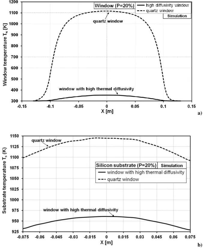
Figure 5 shows an example of comparison of the temperature profiles of the substrate and of the window for 20% power. Similar results are obtained for the other powers. As desired, the overall temperature of the quartz window is in the magnitude of its initial temperature of 300 K. For the substrate, there is a lag down of its temperatures. The decrease of the overall temperature of the window causes a lessening of the wafer one. Indeed, the absorption-emission exchange of radiations in the infrared domain (beyond 4 µm) between the quartz window and the wafer [9] is limited because the temperature of the window is reduced. The high temperature quartz window behaves like an additional heat source due to the absorption and storage of infrared radiative heat beyond 4 µm. Since the temperature of the dissipative window is low, its emission is negligible.
a)
b)
Figure 5 Temperature profile for 20% lamp electrical power of the window (a) and of the silicon wafer (b) with a high thermal diffusivity (modification) and for a low one (quartz) of the window.
Logerais et al. in Heat Transfer Engineering, 36(13) (2015) 1111-1121
As there is a shift of the temperature of the silicon wafer, it is interesting to compare the center-to-edge temperature difference ΔTs versus the center temperature of the substrate
Ts(x = 0) obtained with the modified window and with the quartz one (figure 6).
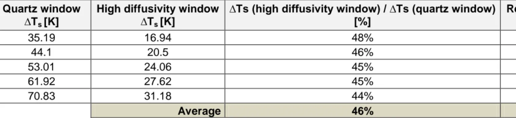
To appreciate the effect of the high diffusivity window, the center-to-edge temperature of the window with high diffusivity is divided by the one of the quartz window to calculate the temperature homogeneity improvement:
quartzwindow
T window y diffusivit high T 1 reduction s s Δ Δ (10)The reduction is calculated by taking into consideration the quartz affine equations obtained with the fittings in figure 6. For wafer temperature ranging 900–1300 K, the effect is calculated in table 2. The temperature difference is diminished by 54% with the high thermal diffusivity window. The temperature difference between the center and the edge of the window therefore affects the one of the substrate. However, as in the case of the absence of window [8], the temperature difference between the center and the edge of the wafer is not zero. The reduction of the nonuniformity of temperature is significant but not total with a heat dissipating window. The low thermal diffusivity therefore is not the only cause for nonuniformity, but we now know that it contributes to 54% of the difference in temperature of the substrate. The effect of the lamps which supply radiative heat in cones, all with the same electrical power, and the one of the reflective walls of the furnace and reactor which direct radiation onto the wafer have both a contribution of around 46%.
In addition, these results indicate the limit of different solutions implemented to cool the quartz window during heating processes. As examples, a double window with oil or water flow [18], or a cooling by compressed air or other gases [19,20] have been used. Arrangement in the window to select the absorbed radiation to avoid the overheating of the window was also proposed by Timans et al. [21] in the context of a patent. The maintaining of low temperature for the window, either by cooling or by ensuring that it does not absorb radiations, must be accompanied by a complementary way to obtain a uniform temperature at the surface of the silicon substrate. Different ideas may be suggested to raise the incident radiative heat flux at the edge of the silicon wafer to compensate the one received at its center. This outcome can be obtained for example by leveraging the control of the infrared lamps, by modifying the shape of the reactor wall or by changing the surface properties of the quartz window.
Ts [K]
Quartz window ∆Ts [K]
High diffusivity window ∆Ts [K]
∆Ts (high diffusivity window) / ∆Ts (quartz window) [%] Reduction [%] 900 35.19 16.94 48% 52% 1000 44.1 20.5 46% 54% 1100 53.01 24.06 45% 55% 1200 61.92 27.62 45% 55% 1300 70.83 31.18 44% 56% Average 46% 54%
Figure 6 Center-to-edge temperature difference of the substrate according to the temperature at its center with the high thermal diffusivity (modification) and with a low one (quartz) for the window.
Effect on gas flow
The gas flow concerns the air in the furnace which is at a pressure in the order of the atmospheric one and also the nitrogen in the reactor which is at low pressure (300 Pa). The temperature differences induce natural convection which can be well viewed with velocity vector field with the computational fluid dynamics analyzer.
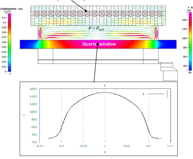
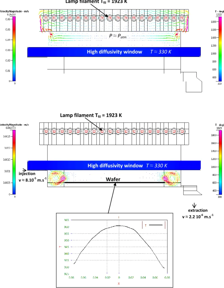
In the furnace, the infrared halogen lamps are at high temperature in the range 1600–2100 K and the furnace reflector wall is at 573 K. Two convection cells are generated with a maximum velocity around 0.117 m.s-1 (see figure 7 and table 3.a). The velocity is higher when there is the hot quartz window at the bottom because the density of hot air is lower. With the high diffusivity window, the air velocity is lower, maximum 0.062 m.s-1 (see figure 8 and table 3.b), because in the lower part of the furnace the air is at a temperature around the ambient one (figure 9). Hence the convection occurs in the upper part of the furnace (figure 8).
In the reactor, the velocity is lower because the pressure inside the reactor is nether (300 Pa) contrary to the air pressure of the furnace which is in the magnitude of the atmospheric pressure. In the reactor, the nitrogen flows from the inlet (injection) to the outlet (extraction). Besides, the reactor wall is kept cool (300 K) but the silicon wafer and the quartz window are at high temperature (1000 K). So the temperature difference generates two convection cells but, contrary to the air in the furnace, the velocity is in the range 0–1.8 mm.s-1 when there is the hot quartz window (see figure 7 and table 3.a). When the window dissipates the heat, the temperature at the top is low (figure 9), the strong temperature differences makes the velocity increase in the interval 0–2.7 mm.s-1 (see figure 8 and table 3.b).
Logerais et al. in Heat Transfer Engineering, 36(13) (2015) 1111-1121
Table 3 Effect of the gas flow on
a) the quartz window
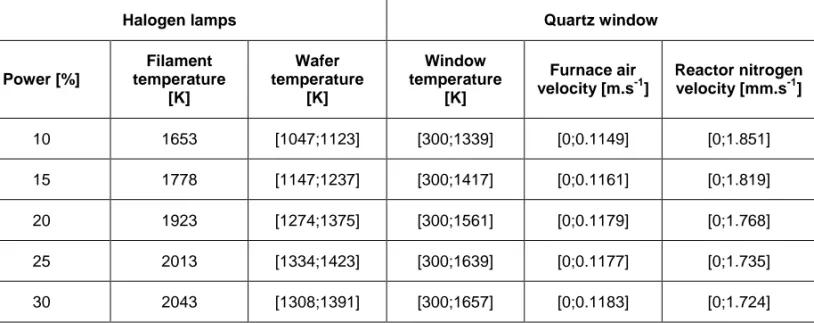
Halogen lamps Quartz window
Power [%] Filament temperature [K] Wafer temperature [K] Window temperature [K] Furnace air velocity [m.s-1] Reactor nitrogen velocity [mm.s-1] 10 1653 [1047;1123] [300;1339] [0;0.1149] [0;1.851] 15 1778 [1147;1237] [300;1417] [0;0.1161] [0;1.819] 20 1923 [1274;1375] [300;1561] [0;0.1179] [0;1.768] 25 2013 [1334;1423] [300;1639] [0;0.1177] [0;1.735] 30 2043 [1308;1391] [300;1657] [0;0.1183] [0;1.724]
b) the high diffusivity window
Halogen lamps High diffusivity window
Power [%] Filament temperature [K] Wafer temperature [K] Window temperature [K] Furnace air velocity [m.s-1] Reactor nitrogen velocity [mm.s-1] 10 1653 [729.1;739.5] [300;329] [0;0.06154] [0;2.635] 15 1778 [800.6;815.8] [300;337.6] [0;0.06226] [0;2.635] 20 1923 [929.1;960.8] [300;355.2] [0;0.06233] [0;2.772] 25 2013 [1015;1046] [300;365.7] [0;0.06218] [0;2.852] 30 2043 [1041;1072] [300;369.2] [0;0.06219] [0;2.876]
As can be seen in figure 9, the air in the lower part of the furnace and the nitrogen in the upper part of the reactor dissipate one part of the absorbed heat above 4 µm by the quartz window. The air in the lower part of the furnace and the nitrogen in the upper part of the reactor are cooled by conduction with the high diffusivity window. The silicon wafer is slightly cooled by convection with the nitrogen in the reactor.
Figure 7 Gas flow and window temperature with quartz window (20% lamp power).
Quartz window
Wafer
Lamp filament Tfil = 1923 K
Lamp filament Tfil = 1923 K
Quartz window injection v ≈ 6.10-5 m.s-1 P = 300 Pa P ≈ Patm extraction v ≈ 1.5.10-6 m.s-1
Logerais et al. in Heat Transfer Engineering, 36(13) (2015) 1111-1121
Figure 8 Gas flow and window temperature with high diffusivity window (20% lamp power).
Quartz window
Lamp filament Tfil = 1923 K
P ≈ Patm
High diffusivity window T ≈ 330 K
Wafer Lamp filament Tfil = 1923 K
High diffusivity window
injection
v ≈ 8.10-5 m.s-1 P = 300 Pa
extraction v ≈ 2.2 10-6 m.s-1
Figure 9 Temperature field for the case of 10% lamp power a) with quartz window b) with high diffusivity window.
Implementation of the infrared window
The assumptions were made for the high diffusivity window to have reasoning on thermal properties. Nevertheless, the implementation of such a window can be achieved by various materials. To provide examples, one can refer to handbooks and manufacturers of infrared windows who propose hard materials with multifarious thermal and radiative properties [22-25]. We have selected in table 4 some hard materials to support the used pressures with high transmissivity around the peak of emission of infrared lamps close to 1 µm. Sufficient thickness has to be considered. We indicate the relative diffusivity regarding the quartz one, a/aquartz. Gallium arsenide (GaAs), gallium lanthanum sulphide (GLS) and diamond cubic
carbon windows permit much higher diffusivity in the same order of the hypothetic material considered but their transmissivities are less than 75%. The group of windows composed of sapphire window, spinel, magnesium fluoride (MgF2) and magnesium oxide (MgO) have
diffusivities between 12 and 17 times higher than the one of the quartz and transmissivities above 75%. Calcium fluoride (CaF2), rubidium chloride (RbCl), magnesium fluoride (MgF2)
have transmissivities above 90% like the quartz. Magnesium fluoride (MgF2) shows an
interesting compromise with a diffusivity 14 times higher than the one of the quartz and a similar transmissivity of 90% at 1 µm.
a)
b)
High diffusivity window
Wafer Wafer
quartz window
Lamp filament Tfil = 1653 K
Lamp filament Tfil = 1653 K
air (Patm)
nitrogen (300 Pa )
air (Patm)
Logerais et al. in Heat Transfer Engineering, 36(13) (2015) 1111-1121 Window Thermal conductivity k [W.m-1.K-1] Specific heat cp [J.kg-1.K-1] Density ρ [kg.m-3] Diffusivity a [m.s-2] Relative diffusivity a/aquartz Transmissivity around 1 µm [%] Melting temperature [°C] Quartz 2 1000 2649 7.6 10-7 1.0 90 1710 Mica 0.7 210 3000 1.1 10-6 1.5 80 600 Lanthanum Fluoride (LaF3) 5.1 506 5940 1.7 10-6 2.2 90 1493 Calcite 5.526 852 2710 2.4 10-6 3.2 90 825 Calcium Fluoride (CaF2) 9.71 854 3180 3.6 10-6 4.7 95 1360 Potassium Bromide (KBr) 4.816 435 2753 4.0 10 -6 5.3 90 730 Rutile (TiO2) 12.5 711 4252 4.1 10-6 5.5 70 1840 Aluminium nitride (AlON) 12.3 781 3690 4.3 10 -6 5.7 > 80 2150 Potassium Chloride (KCl) 6.53 690 1990 4.8 10 -6 6.3 87.5 776 Cadmium Telluride (CdTe) 6.2 210 6200 4.8 10-6 6.3 65 1092 Yttrium Aluminium Garnet (YAG) 12.9 590 4560 4.8 10-6 6.4 85 1940 Rubidium Chloride (RbCl) 7.6 418 2800 6.5 10-6 8.6 92.5 715 Spinel 25 819,1 3580 8.5 10-6 11,3 87,5 2135 Sapphire window 27.21 763 3970 9.0 10 -6 11.9 85 2040 Zinc Selenide (ZnSe) 18 339 5270 1.0 10 -5 13.3 70 1525 Magnesium Fluoride (MgF2) 33.6 1003 3176.6 1.1 10-5 14.0 90 1255 Rubidium Iodide (RbI) 9.9 242 3550 1.2 10 -5 15.3 87.5 642 Zinc Sulphide Multispectral (ZnS) 27.2 515 4090 1.3 10-5 17.1 75 1827 Magnesium Oxide (MgO) 42 877 3580 1.3 10 -5 17.7 85 2800 Gallium Arsenide (GaAs) 48 360 5135 2.6 10-5 34.4 55 1511 Gallium Lanthanum Sulphide (GLS) 0.43 0.54 4040 2.0 10-4 261.1 75 830 Model case 400 130 2649 1.2 10-3 1538.5 90 1710 Diamond Cubic Carbon (C) 2600 500 3510 1.5 10-3 1962.2 70 3497
CONCLUSIONS
Numerical simulations of a rapid thermal system without optimization in steady-state led to a better understanding of the effect of the thermal properties of the window on the homogeneity of the temperature of a silicon wafer for constant heating power. A close relationship between the temperature distribution of the silicon substrate and the one of the quartz window is established when superposing their profiles. Temperature differences between the center and the edge of the substrate and the window augment linearly and parallely according to the lamp heating power.
We therefore found a way to reduce the temperature of the quartz window in the model. As the thermal diffusivity of the quartz is low, calculations were performed with a much higher diffusivity so as to have a heat dissipative window. The center-to-edge temperature difference of the window is lessened. This effect is appreciated on the wafer temperature. In this case where the window is an excellent heat sink, the temperature difference between the center and the edge of the silicon substrate is reduced by 54%. The latter result corresponds to the best that can be obtained with a quartz window maintained at low temperature. This significant but not total decrease thus shows that the thermal behavior of the window is not the only cause for uneven temperature of the wafer. The obtention of a uniform temperature at the surface of the wafer requires associating a method to reduce the temperature of the window during the heating process and another one to balance the radiative heat flux received on the surface of the silicon substrate. To implement the high diffusivity window, materials having this thermal feature have been selected like magnesium oxide window having a diffusivity 14 times higher than the one of the quartz and a similar transmissivity of 90% at 1 µm.
ACKNOWLEDGMENTS
The authors thank the Centre des Ressources Technologiques de Sénart (CRTS) for the support and the company AnnealSys and in particular the director, Mr. Frank Laporte for his help and for providing an AS-One 150 equipment for the present study. They also wish to thank Mrs. Wilhelmina Logerais, a native English speaker, for her help with English.
Logerais et al. in Heat Transfer Engineering, 36(13) (2015) 1111-1121
NOMENCLATURE
a thermal diffusivity, m².s-1
A area of patch, m2
cp specific heat, J.kg-1.K-1
h0 total mass enthalpy, J.kg-1
i mass internal energy, J.kg-1
I radiative energy intensity, W.m-2.sr-1
k thermal conductivity, W.m-1.K-1
M exchange matrix
n unit vector normal to surface
p static pressure, Pa
P lamp electrical power, %
q radiative heat flux density, W.m-2
Q radiative heat flux, W
r position
S source term
t time, s
T temperature, K
u,v velocity components relative to x, y, m.s-1
V velocity, m.s-1 x, y cartesian coordinates Greek symbols δ Kronecker symbol ε emissivity κ absorption coefficient
µ dynamic viscosity, Pa.s-1
Ω beam propagation direction, sr
ρ density, kg.m-3 or reflectivity
σ diffusion coefficient or Stephan-Boltzmann constant, 5.669 10-8 W.m-2.K-4
τ viscous stress tensor, Pa
Φ phase function
Subscripts
b blackbody
fil lamp filament
h heat
Mx x-momentum
qw quartz window
w window
i,j patch
REFERENCES
[1] Borisenko, V.E., Hesketh, P.J., Rapid thermal processing of semiconductors, Plenum Press, New York, 1997.
[2] Su, A.J., Jeng, J.C., Huang, H.P., Yu, C.C., Hung, S.Y., Chao, C.K., Control relevant issues in semiconductor manufacturing: Overview with some new results, Control Engineering Practice, vol. 15, pp. 1268–1279, 2007.
[3] Balakrishnana, K.S., Edgar T.F., Model-based control in rapid thermal processing, Thin Solid
Films, vol. 365, pp. 322-333, 2000.
[4] Makarevich, Y., et al., Modeling of processes of ion implantation and annealing in silicon structures, Radiation Interaction with Material and Its Use in Technologies, Kaunas University Technology press, Kaunas, pp. 316–319, 2012.
[5] Prostomolotov, A.I., Verezub, N.A., Mezhennii, M.V., Reznik, V.Y., Thermal optimization of CZ bulk growth and wafer annealing for crystalline dislocation-free silicon, Journal of Crystal Growth, vol. 318, no.1, pp. 187–192, 2011.
[6] Habuka, H., Wada, T., Sakurai, T., Takeuchi, T., Aihara, M., Heat balance evaluation for rapid thermal processing system design, Journal of the Electrochemical Society, vol. 152, no. 12, pp. 924–928, 2005.
[7] Logerais, P.O., Chapron, D., Garnier, J., Bouteville, A., Validation of a Rapid Thermal Processing model in steady-state, Microelectronic engineering, vol. 85, no. 11, pp. 2282–2289, 2008.
[8] Logerais, P.O., Girtan, M., Bouteville, A., Influence of the quartz window in a Rapid Thermal Processing apparatus, Journal of Optoelectronics and Advanced Materials, vol. 8, no. 1, pp. 139– 143, 2006.
[9] Logerais, P.O., Chapron, D., Bouteville, A., Transient simulations of a Rapid Thermal Processing apparatus, Journal of Optoelectronics and Advanced Materials, vol. 9, no. 4, pp. 1082–1086, 2007. [10] Annealsys company products, available at
http://www.annealsys.com/annealsys-products/rtp-rtcvd/ , accessed Feb. 2013.
[11] Patankar, S.V., Numerical Heat Transfer and Fluid Flow, Hemisphere Publishing Corporation, McGraw-Hill, New York, 1980.
[12] Modest, M.F., Radiative Heat Transfer, McGraw-Hill, New York, 1993.
[13] Logerais, P.O., Étude du chauffage d’un substrat de silicium dans un système thermique rapide (RTP : Rapid Thermal Process), Ph.D. thesis, Arts et Métiers ParisTech, France, 2007.
[14] Palik, E.D., Handbook of Optical Constants of Solids, Academic Press, New York, 1998.
[15] Mazumder, S., Kersch, A., A fast Monte Carlo scheme for thermal radiation in semiconductor processing applications, Numerical Heat Transfer, Part B: Fundamentals, vol. 37, pp. 185–199, 2000.
[16] CFD Research Corporation, CFD’ACE (U) Module Manual, Version 2013, Huntsville, 2013. [17] Bejan, A., Heat Transfer, JohnWiley and Sons, Singapour, 1993.
[18] Slaoui, A., Bourdais, S., Beaucarne, G., Poortmans, J., Reber, S., Polycrystalline silicon solar cells on multiple substrates, Solar Energy Materials and Solar Cells, vol. 71, no. 2, pp. 245–252, 2002.
[19] Dassau, E., Grosman, B., Lewin, D.R., Modelling and temperature control of rapid thermal processing, Computers and Chemical Engineering, vol. 30, pp. 686–697, 2006.
[20] Yin, C.P., Hsiao, C.C., Lin, T.F., Improvement in substrate temperature uniformity and flow pattern in a lamp heated rapid thermal processor, Journal of Crystal Growth, vol. 217, pp. 201– 210, 2000.
[21] Timans, J.P., Devine, D.J., Lee, Y.J., Hu, Y.Z., Bordiga, P.C., Selective reflectivity process chamber with customized wavelength response and method, United States Patent 07115837, october 3rd 2006.
[22] Shinde, S.L., Goela, J., High Thermal Conductivity Materials, Springer, New York, 2006. [23] Weber, M.J., Handbook of Optical Materials, CRC Press, Boca Raton, Florida, 2002. [24] Characteristics available at http://www.crystran.co.uk/optics-definitions , Feb. 15, 2014. [25] Characteristics available at http://www.edmundoptics.com/FR/ , Feb 15, 2014.
Logerais et al. in Heat Transfer Engineering, 36(13) (2015) 1111-1121 Pierre-Olivier Logerais is a Senior Lecturer in Energetics at the Université Paris-Est Créteil (France) since 2009. He obtained his PhD degree in heat transfer and materials at the Arts et Metiers ParisTech engineering school in Angers (France) in 2007. His work dealt with the numerical modeling and optimization of a Rapid Thermal Process (RTP) system. In his postdoctoral research, he investigated on mass convective diffusion in fluid flow. Since 2009, he has developed various models and investigations on energetic systems at the CERTES laboratory: CFD calculation of radiative transfer in RTP systems, circuit-based approach of photovoltaic energy and of electrical storage by ultracapacitors, reanalysis of the heat transfer and study of fluid flow near critical point.
Raouf Khelalfa is a postdoctoral research worker on theoretical and numerical modeling of heat and mass transfer. His research work over the past decade at the Institut Jean Le Rond d’Alembert (Université Paris 6, France) and at the CERTES (Université Paris-Est Créteil, France) deals with two themes. He studied the infiltration flow passing at the vicinity of the thermodynamic critical point and namely the effect of the anomalies near critical point. His results allowed to quantify the leakage rate in sealing problems encountered in the transportation of high pressure fluid. In the second topic, he developed new algorithms for reanalysis of numerical resolution for heat transfer systems discretized by finite elements and finite differences to gain computation time in parametric solving.
Olivier Riou is currently a Senior Lecturer in Physics at the IUT of Sénart and a member of CERTES laboratory at the Université Paris-Est Créteil (France). He completed his PhD thesis on heat transfer measurements at very low temperatures at the Université Joseph Fourier, Grenoble 1 (France). His research work focuses mainly on non destructive techniques: quantitative thermography approaches and on analysis tools for vibrations. Recently, he instrumented several benches to characterize materials, production and electrical storage in photovoltaic systems. On a broader scale, his teaching deals with management of industrial and societal risks.
Jean-Félix Durastanti is Professor in Energetics at the Université Paris-Est Créteil (France) since 1997 and member of the laboratory CERTES. He defended his PhD thesis at the Université de Provence (France) in 1985 to study a solar power plant steam production and proposed new numerical schemes to correctly reflect the dispersion of fluids. He obtained his habilitation research degree at the Université de Bourgogne (France) in 1989 with his contribution on the theme of modeling complex systems and heat exchangers in particular spiral exchangers. He currently heads the research group on aging solar cells at the CERTES laboratory. His work focuses on numerical heat transfer modeling including model reduction and thermo-physical characterization of materials. He has co-authored more than 90 referred journal and conference publications. He is a member of the French thermal society.
Anne Bouteville is a professor in Energetics and processes at Arts et Métiers ParisTech engineering school (France). She obtained her PhD degree in 1981 at the Université de Nantes (France) and her State Doctorate in 1987. The same year, she became a Senior Lecturer at the Université d’Angers (France) in section materials where she worked on thin films deposition for microelectronics by the Chemical Vapor Deposition (CVD) method. In 2000, she turned Professor at the LAMPA, a laboratory of Arts et Métiers ParisTech school in Angers (France) where she extended her CVD studies to other applications such as microelectronics, corrosion (Ta), hard and decorative coating (TiN), numerical simulation and currently photovoltaic applications (ZnO doped). In November 2011 she became directress of doctoral training and PhD graduate school co-accredited by both the engineering schools Arts et Métiers ParisTech and the École des Mines of Paris.
![Figure 2 Example of agreement between the experimental wafer temperature profiles and the calculated ones for 20% lamp electrical power (T fil is the lamp filament temperature, see [7,13])](https://thumb-eu.123doks.com/thumbv2/123doknet/7425229.219387/6.892.80.784.807.1205/example-agreement-experimental-temperature-profiles-calculated-electrical-temperature.webp)