HAL Id: hal-01084545
https://hal.archives-ouvertes.fr/hal-01084545
Submitted on 4 Jul 2019
HAL is a multi-disciplinary open access
archive for the deposit and dissemination of
sci-entific research documents, whether they are
pub-lished or not. The documents may come from
teaching and research institutions in France or
abroad, or from public or private research centers.
L’archive ouverte pluridisciplinaire HAL, est
destinée au dépôt et à la diffusion de documents
scientifiques de niveau recherche, publiés ou non,
émanant des établissements d’enseignement et de
recherche français ou étrangers, des laboratoires
publics ou privés.
Kinematic analysis of a single-loop reconfigurable 7R
mechanism with multiple operation modes
Xiuyun He, Xianwen Kong, Damien Chablat, Stéphane Caro, Guangbo Hao
To cite this version:
Xiuyun He, Xianwen Kong, Damien Chablat, Stéphane Caro, Guangbo Hao. Kinematic analysis
of a single-loop reconfigurable 7R mechanism with multiple operation modes. Robotica, Cambridge
University Press, 2014, 32 (7), pp.1171-1188. �10.1017/S0263574713001197�. �hal-01084545�
1
Kinematic analysis of a single-loop reconfigurable RRRR-RRR
mechanism with multiple operation modes
Xiuyun He†, Xianwen Kong†
,*, Damien Chablat‡, Stéphane Caro‡, Guangbo Hao§
†
School of Engineering and Physical Sciences, Heriot-Watt University, Edinburgh, EH14 4AS, UK‡
Institut de Recherche en Communications et en Cybernétique de Nantes (IRCCyN), Université Nantes Angers Le Mans, Nantes, France§
Department of Electrical and Electronic Engineering, School of Engineering, University College Cork, Cork, Ireland*
Corresponding author. Email: [email protected].
ABSTRACT
This paper deals with the kinematic analysis of a single-loop reconfigurable RRRR-RRR mechanism with multiple operation modes (SLR7RMMOM), which is composed of seven revolute (R) joints and can switch from one operation mode to another one without disconnection and reassembly. The algorithm for the inverse kinematics of the serial open 6R chain using kinematic mapping is adopt to deal with the forward kinematics for the SLR7RMMOM. 13 sets of solutions for the SLR7RMMOM are computed. Among these solutions, nine sets are real solutions, which are verified using the CAD models of the mechanism. It is shown that the present mechanism has three operation modes: translational mode and two 1-DOF planar modes. The transitional configurations between the three modes are also identified.
KEYWORDS: Single-loop reconfigurable mechanism; Multiple operation modes; Forward kinematics; Kinematic mapping; Transitional configuration
1. Introduction
Reconfigurable parallel mechanisms (RPMs) have been received increasing attention from researchers around the world. One class of RPMs can generate different operation modes to fulfil variable tasks based on a sole mechanism. Different approaches have been proposed to design RPMs generating multiple motion patterns. Several classes of RPMs have been developed such as modular reconfigurable
mechanisms,1,2 metamorphic mechanisms,3 kinematotropic
mechanisms,4 variable actuated mechanism,5 and
reconfigurable mechanisms with multiple operation modes. This paper focuses on a reconfigurable mechanism with multiple operation modes since this class of RPMs can be reconfigured without disassembly and without increasing the number of actuators. A systematic approach has been proposed6,7 for the synthesis of reconfigurable mechanisms with multiple operation modes, including single-loop
reconfigurable mechanisms with multiple operation modes6
and multiple-loop reconfigurable mechanisms with multiple
operation modes.8
Meanwhile, several approaches have been developed to deal with the kinematics and singularity analysis of serial and
parallel mechanisms, such as different evaluation algorithm,9
screw theory algorithm10 and kinematic mapping algorithm.12
Husty and Pfurner have made a significant contribution to the
algebraic approach to the kinematic analysis of
mechanisms.11-13 It has been shown that algebraic method is very efficient for both direct (forward) and inverse kinematic analysis of mechanisms.
This paper aims to analyze a single-DOF (degree-of-freedom) single-loop reconfigurable RRRR-RRR mechanism with multiple operation modes (SLR7RMMOM) using the effective algorithm for the inverse kinematics of a general serial 6R manipulator. Here R denotes a revolute joint. The operational modes and transitional configurations will be identified. The paper is organised as follows. Section 2 describes the 1-DOF SLR7RMMOM. In Section 3, the forward kinematics analysis for the mechanism is undertaken within three steps mainly using the kinematic mapping method, and the solutions with respect to one given input angle are verified using CAD software. Based upon the results from Section 3, a series of input angles are given and the operation modes and transitional configurations are obtained in Section 4. Finally, conclusions are drawn.
2. Description of a 1-DOF SLR7RMMOM
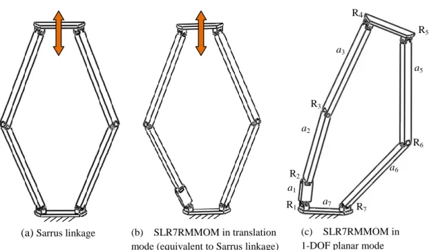
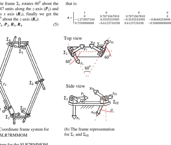
It is well known that the Sarrus linkage (Fig. 1(a)), which is composed of two groups of three R joints with parallel joint axes (rotational axes), is used to control the 1-DOF translation of the moving platform along a straight line with respect to the base. Since the Sarrus linkage is an overconstrained mechanism, we can insert one additional R joint between the two joints of a link to obtain a non-overconstrained 1-DOF single-loop RRRR-RRR mechanism (Fig. 1(b)).14 Such a mechanism must have at least two operation modes. In the translational operation mode, it works as the Sarrus linkage in which the moving platform translates along a straight line (Fig. 1(b)). In the 1-DOF planar operation mode, the moving platform undergoes a 1-DOF general planar motion (Fig. 1(c)). Therefore the above RRRR-RRR mechanism is a SLR7RMMOM.
In this SLR7RMMOM, link 7 is the base, and link 4 is specified as the moving platform. Links 4 and 7 are identical and the link lengths and the axes of the R joints must satisfy the following conditions:
R1//R3//R4┴R2, (1)
R5//R6//R7, (2)
a1+a2=a3=a5=a6 (3)
where Ri (i=1,2, …,7) is the unit vector along the axis of joint
2
Fig. 1. Construction of a SLR7RMMOM
The SLR7RMMOM has at least two operation modes. Whether it has additional operational modes is unclear from only the construction of the mechanism. In the next section, we will discuss the kinematic analysis of the SLR7RMMOM in order to identify all of its operation modes as well as transition configurations that the mechanism can switch from one operation mode to another.
3. Kinematics Analysis and Numerical Example
Using the approach to the inverse kinematics for the general 6R mechanism, 11-13 one can perform the kinematic analysis of the SLR7RMMOM. Then all the operation modes and transition configurations of the mechanism can be identified.
3.1. D-H Parameters for the mechanism
In order to define the transformation relations between the links, the coordinate frames Σi is attached to link i as follows:
the zi-axis coincides with the axis of joint Ri, the xi-axis aligns
with the common perpendicular to the zi-1- and zi-axes, and
the yi-axis is defined by the right-hand rule (Fig. 2). With this
notation one could write the transformation matrix (Ti) from
Σi to Σi+1 as: [ ] [ ] (4) where θi and di are the revolute angle and distance between
the two x-axes of links i and i+1, respectively, and αi and ai
are the twist angle and distance between the two z-axes of links i and i+1, respectively.
The SLR7RMMOM can be regarded as a 6R serial mechanism (Fig. 3(a)) with link 6 as the end-effector (EE), the coordinate frame on which is set as follows. Its z-axis (zEE)
coincides with the axis of joint R7 and its x-axis aligns with
the common perpendicular to the z6-axis and the zEE-axis. The
angle between the xEE-axis and the vertical line(θ) is defined
as the input angle of the SLR7RMMOM. The D-H parameters of the 6R mechanism are shown in Table 1, which should satisfy the conditions given in Section 2.
Fig. 2. D-H parameters (Σ is the coordinate frame system)
Table 1. D-H parameters for the loop
i ai di αi θi 1 0.80 0 900 θ1 2 3.00 0 −900 θ2 3 3.80 0 00 θ3 4 0 1.47 −1200 θ4 5 3.80 1.47 00 θ5 6 3.80 0 00 θ6
In addition, the angle between the axes of joints R1 and R7
is 600, θ is specified as 450 and a7 is 1.47. Therefore, the
pose of end-effector ΣEE with respect to Σ1 (A) can be
Σ
iΣ
i+1 xi+1 yi+1 zi+1 Link i yi zi θi αi di ai Link i+1 xi R5 a5 R6 a6 a7 R1 a1 R2 a2 R3 a3 R4 R7(a)
Sarrus linkage (b) SLR7RMMOM in translationmode (equivalent to Sarrus linkage)
(c) SLR7RMMOM in
3
obtained (Fig. 3(b)). First, the frame Σ1 rotates 600 about the x-axis (R1), then it moves 1.47 units along the z-axis (P2) and
rotates another 600 about its x axis (R3), finally we get the
frame ΣEE after rotating 450 about the z-axis (R4):
(5) that is: [ ]
)
Fig. 3. Coordinate frame system for the SLR7RMMOM
3.2. Solutions for the kinematic analysis
The algorithm for the inverse kinematics analysis of a general 6R serial manipulator presented in 11-13 mainly used kinematic mapping method. Using this method, an Euclidean displacement can be mapped into a point on a study quadric (S62) in a seven dimensional space, the so called kinematic
mapping space P7, where the point is displayed by eight study parameters. In the kinematic mapping space, the constraint manifold of a 2R-chain is the intersection of a 3-space with the S62, and the constraint manifold of a 3R chain is the
intersection of a set of 3-spaces with the S6 2
, where the set of 3-spaces is called Segre Manifold (SM).11 The SM of a 3R-chain can be represented by a set of four bilinear equations in the eight homogenous study parameters, which is denoted by
z0, z1, …, z7, and one additional parameter corresponding to
the tangent half of one joint angle out of the three joint angles. That means that there are three SMs (SMi, i=1, 2, 3) which
were presented by three sets of four equations for a 3R-chain. The 6R serial chain associated with the 1-DOF SLR7RMMOM is further decomposed into two 3R chains, the left 3R one (1-2-3) with end effector frame ΣL and the
right 3R one (6-5-4) with end effector frame ΣR (Fig. 4). The
pose of the frame ΣL with respect to Σ1 (TL) and the pose of
the frame ΣR with respect to Σ1 (TR) can be obtained based on
Eqs. (4) and (5):
(6.a)
(6.b)
In some discrete, the frames ΣL and ΣR have to coincide,
which means there is intersection among SML, SMR and S62.
The equations for SMs the can be derived from Eq. (6). Three
sets of four equations can be obtained for the left or the right 3R chain, and each depends on one out of three joint angles.14 One needs to select one of the three sets of four equations for the left 3R-chain and one of the three sets of four equations for the right 3R-chain according to different situations14 before doing further calculation.
Fig. 4. Decomposing the loop into two 3R chains
In some cases, not all the three SMs can be selected 13. If one select one SM depending on one R joint with the joint axes of the remaining two parallel or intersected, which means the SM lies on the S6
2
, then the intersection with the
S62 fails. Therefore, we select SM3, which refers to four
equations in (tangent half angle of θ3), for the left
3R-Σ
EEΣ
6Σ
5Σ
RΣ
LΣ
3Σ
2Σ
1Σ
EEΣ
6Σ
5Σ
4Σ
3Σ
2Σ
1 x3 z3 y3(a) Coordinate frame system for the SLR7RMMOM
Σ
EEΣ
1 xEE yEE y1 θ z1 x1Σ
1Σ
EE 600 z1 y1 zEE yEE 600 60 0(b) The frame representation for Σ1 and ΣEE
Top view
Side view
4
chain since the axes of joints R1 and R2 do not intersect and
are not parallel. For the right 3R-chain, we select SM5 with
four equations in ̅ (minus tangent half angle of θ5),
because the axes of joints R4 and R5 intersect and the axes of
joints R5 and R6 are parallel. Thus eight equations for the 6R
serial mechanism are obtained as follows:
(7) (8) (9) (10) ̅ ̅ ̅ ̅ ̅ ̅ ̅ ̅ ̅ (11) ̅ ̅ ̅ ̅ ̅ ̅ ̅ ̅ ̅ (12) ̅ ̅ ̅ ̅ ̅ ̅ ̅ ̅ ̅ (13) ̅ ̅ ̅ ̅ ̅ ̅ ̅ ̅ ̅ (14) (15)
Including the equation for the S62 shown in Eq. (15), we obtain nine bilinear equations in ten unknowns (Eqs. (7)-(15)). Because z0, z1, …, z7 are homogeneous, so one of them can be normalize to 1. Solving seven of the nine equations to get the eight study parameters for z0, z1, …, z7 in and ̅ , and substituting the solutions into the remaining two equations, we obtain two equations in and ̅ named E1 and E2 as ̅ ̅ ̅ ̅ ̅ ̅ ̅ ̅ ̅ ̅ ̅ ̅ ̅ ̅ ̅ ̅ ̅ ̅ 0 (16) ̅ ̅ ̅ ̅ ̅ ̅ ̅ ̅ ̅ ̅ ̅ ̅ ̅ ̅ ̅ ̅ ̅ ̅ ̅ ̅ ̅ ̅ ̅ ̅ ̅ ̅ ̅ ̅ ̅ ̅ ̅ ̅ ̅ ̅ ̅ ̅ ̅ ̅ ̅ ̅ ̅ ̅ ̅ ̅ ̅ ̅ ̅ ̅ ̅ ̅ ̅ (17)
5
Using the resultant to eliminate ̅ from Eqs. (16) and (17),
one polynomial equation of degree 56 in named E can be
derived as follows. 0 (18)
The solutions to are = ± I (I is the unit
imaginary number). The corresponding points in P7 lie on the
exceptional generator, which have to be cut out of the S62.
The solutions of polynomial of 10 degrees squared are points
with coordinate (0, 0, 0, 0, 0, 0, 0, 0), which do not lie on the
S62 and the solutions of polynomials of degree 4 are points lie
on the exceptional 3-space of the S62.13 Then the polynomial
of degree 16 gives the 16 solutions:
=[0.08366283786, 0.3610109062, 1.000000000, 6.521970015, 59.40599134, 4.132441204 , 5.081725257 ,
0.4234204659+2.169839731 I, −0.07511185210+1.019253419 I, −6.650597562 +3.156689159 I,
−0.3581658035, −1.000000001, −1.507896627, −6.650597562 3.156689159 I,
−0.07511185210−1.019253419 I, 0.4234204659−2.169839731 I]
Then the solutions for are substituted back to E1 and E2,
the common solutions for ̅ with their corresponding are
the solutions as desired. Please note only 12 sets of solutions could be easily obtained where the remaining four solutions
for tend to be infinite, such as 5.081725257 , i.e. θ3
approaches to be 1800. The situation that θ3=1800 does exist
when the joints on the platform and the base coincide. It is special configurations for the 1-DOF SLR7RMMOM, as shown in Fig. 5(i).
The remaining four joint angles for the normal 12 sets of solutions could be solved by the other sets of four equations for SM1, SM2, SM4 and SM6.
As to the above four particularly configurations in which tend to be infinite, there is one set of real solutions: θ2=00, θ3=1800, θ6=1800, θ1, θ4 and θ5 can be any value. This set of
solutions can be easily verified by observation. The complex solutions associated with the remaining three particularly configurations are omitted in this paper.
Finally, 13 sets of solutions for the forward kinematics analysis of the single loop are obtained, as listed in Table 2.
Table 2. Solutions for the loop
Solutions θ1(deg) θ2(deg) θ3(deg) θ4(deg) θ5(deg) θ6(deg)
Solution 1 −173.940 20.726 9.565 −3.504 −155.426 −45.598 Solution 2 135.000 0.000 90.000 −45.000 −135.000 −90.000 Solution 3 −135.000 0.000 −90.000 45.000 −135.000 −90.000 Solution 4 −4.576 15.737 178.071 −2.648 −70.339 −172.852 Solution 5 −78.354 118.963 −112.897 −145.457 86.692 −119.924 Solution 6 −154.651 73.117 39.700 −14.351 131.208 90.703 Solution 7 −25.162 72.737 −39.412 −165.750 −41.899 90.473 Solution 8 141.385 −94.455 162.566 158.819 156.631 −137.538 Solution 9 −54.493− 109.370I 163.879+ 10.798I −106.507− 186.806I −127.985+ 77.436I 58.785+ 82.626I −100.688− 144.387I Solution 10 −54.493+ 109.370I 163.879− 10.798I −106.507+ 186.806I −127.985− 77.436I 58.785− 82.626I −100.688+ 144.387I Solution 11 93.401+ 63.964I −142.300+ 1.679I 167.711+ 54.093I 105.690+ 9.871I 112.781+ 77.655I −156.361− 28.617I Solution 12 93.401− 63.964I −142.300− 1.679I 167.711− 54.093I 105.690− 9.871I 112.781− 77.655I −156.361+ 28.617I
Solution 13 Any value 0.000 180.000 Any value Any value 180.000
Note: I is the unit imaginary number
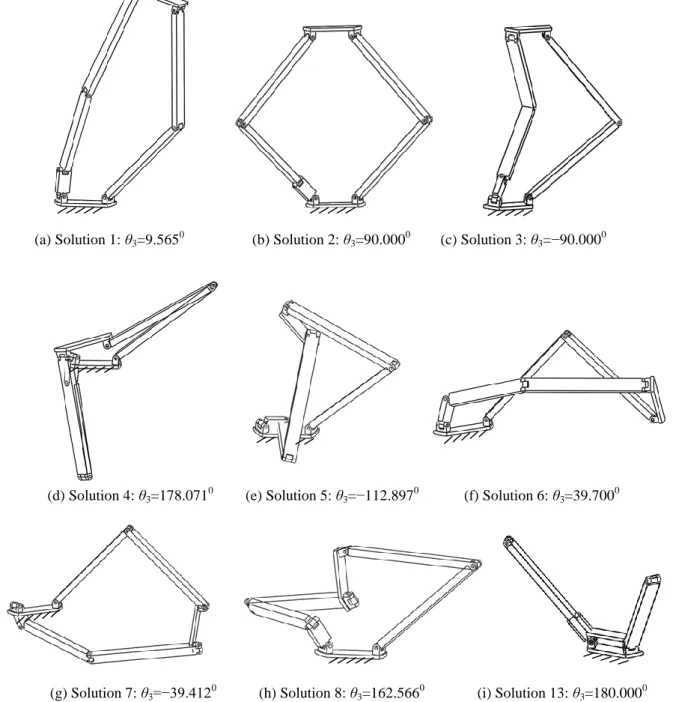
The above real solutions for the kinematic analysis have been verified using the CAD models for the 1-DOF
SLR7RMMOM. The CAD configurations associated with these solutions are shown in Fig. 5.
6
(a) Solution 1: θ3=9.5650 (b) Solution 2: θ3=90.0000 (c) Solution 3: θ3=−90.0000
(d) Solution 4: θ3=178.0710 (e) Solution 5: θ3=−112.8970 (f) Solution 6: θ3=39.7000
(g) Solution 7: θ3=−39.412 0 (h) Solution 8: θ3=162.566 0 (i) Solution 13: θ3=180.000 0
Fig. 5. CAD configurations corresponding to the real solutions
4. Operation Modes and Transitional Configurations
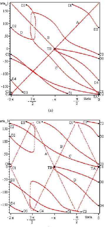
As the input angle θ changes, a series of solutions corresponding to different input angles can be obtained accordingly. Then via plotting the joint angles against the input angle, we illustrate the operation modes and transitional configurations of the 1-DOF SLR7RMMOM (Fig. 6). All the operation modes and transitional configurations of the
mechanism can be obtained from the plotting of angles θ1 and
θ3 against the input angle θ.
Figure 6 shows that there are two straight lines A and B and two closed curves C (C0-C1-C2-C0 in Fig. 6(a) or C0-C1
-C2-C3-C4-C0 in Fig. 6(b)) and D (D0-D1-D2-D3-D4-D0)
designating the operations modes. Lines A and B are associated with translation operation mode, while the closed curves C and D are associated with two 1-DOF planar
operation modes separately. Therefore, the mechanism has three operation modes but not only two operation modes. This could be easily verified by comparing the straight lines and closed curves to their corresponding operation mode figures in Fig. 5. Line A corresponds to Fig. 5(b), Line B corresponds to Fig. 5(c), closed curve C corresponds to Fig. 5(a), and closed curve D corresponds to Fig. 5(f).
In the following, the transitional configurations between three operation modes are analyzed. By comparing the two plotting figures (Fig. 6), two intersecting points TA and TB, through which both operation modes pass in both the plotting figures are apparently observed, which represent the transitional configurations (Fig.7). The input angles corresponding to the transitional configurations are shown in Table 3.
7
(a)
(b)
Fig. 6. Plotting of two rotational angles (θ1 and θ3) against
input angle θ: a) θ1 (deg) in vertical axis versus θ(rad) in the
horizontal axis; b) θ3 (deg) in vertical axis versus θ(rad) in
the horizontal axis
Table 3. Transitional configurations Transition
points
Input angle
θ in degree Modes
TA 00 Translational mode & 1-DOF
planar mode one (curve C)
TB 1800 Translational mode & 1-DOF
planar mode two (curve D)
(a) TA: θ=00 (b) TB: θ=1800 Fig. 7. Transitional configurations of the SLR7RMMOM.
5. Conclusions
The kinematics analysis of a novel 1-DOF SLR7RMMOM has been implemented. Using the algorithm for the inverse kinematics of a general serial 6R manipulator, a set of solutions for the 1-DOF SLR7RMMOM have been obtained with the real solutions verified through the CAD model of the mechanism. The solutions against a series of input angle have been plotted in two figures, which show that the mechanism has three operation modes: translational mode and two 1-DOF planar modes. Transitional configurations have also been identified where the mechanism can switch from one operation mode to another.
When switching the proposed 1-DOF SLR7RMMOM from one operation mode to another, neither the extra actuator nor disassembly is needed. Therefore, this reconfigurable mechanism may be useful for developing energy-efficient manipulators.
The investigation of the operation modes of the mechanism using an algebraic approach15 instead of the numerical approach deserves further application.
Acknowledgement
The authors would like to thank the Royal Society, United Kingdom for the financial support through an International Joint Project No. JP100715. X. He would like to acknowledge the financial support from the SORSAS PhD scholarship in Heriot-Watt University. Special thanks go to Prof. M.L. Husty and Dr. M. Pfurner in Universität Innsbruck, Austria for their valuable help in using their kinematic mapping algorithms.
References
1. Yang, G., Chen, I., Lim, K.M., Huat, Y.S., 1999, “Design and Kinematic Analysis of Modular Reconfigurable Parallel Robots”, 1999 IEEE Conference
on Robotics and Automation, May, 1999, Detroit, MI,
US.
2. Yang, G., Chen, W., Chen, Y., Huat, Y.S., Chen, G., 2001, “Design and Kinematic Analysis of Modular
Reconfigurable Parallel Robot”, Springer, Vol.10:
8
3. Kuo, C., Dai, J., 2009, “Reconfiguration Principles and
Strategies for Reconfigurable Mechanisms”,
ASME/IFToMM International Conference on Reconfigurable Mechanisms and Robots, June 2009,
London, UK.
4. Galletti, C., Fanghella, P., 2001, “Single-loop
Kinematotropic Mechanism”, Mechanism and Machine
Theory, Vol. 36: 743-761.
5. Rakotomanga, N., Chablat, D.,Caro, S., “Kinatostatic Performance of a Planar Mechanism with Variable Actuation”, Jadran Lenarcic and philippe Wenger,
Advances in Robot Kinematics: Analysis and Design, pp.
311-320.
6. Kong, X., Huang, C., 2009, “Type Synthesis of Single-DOF Single-loop Mechanisms with Two Operation Modes”, ASME/IFToMM International Conference on
Reconfigurable Mechanisms and Robots, June 2009,
London, UK.
7. Kong, X., Type synthesis of 3-DOF parallel
manipulators with both planar and translational operation modes. Proceedings of ASME 2011 International Design Engineering Technical Conferences & Computers and Information in Engineering Conference, DETC2011-48510, Washington, USA, August 28-31, 2011.
8. Zlatanov, D., Bonev, I.A., Gosselin, C.M., 2002, “Constraint Singularity as C-Space Singularities”,
Advances in Robot Kinematics-Theory and Application,
J. Lenarčič and F. Thomas eds., Kluwer Academic Publishers, pp. 183-192.
9. Wang, X., Hao, M., Cheng, Y., 2008, “On the Use of Different Evaluation for Forward Kinematics of Parallel Manipulators”, Applied Mathematics and Computation, Vol. 25: 760-769.
10. Bonev, I.A., Zlatanov, D., Gosselin, C.M., 2003, “Singularity Analysis of 3-DOF Planar Parallel Mechanisms via Screw Theory”, Journal of Mechanical
Design, Vol. 125.
11. Husty, M.L., Pfurner, M., Schrocker, H.P., 2007, “A New and Effective Algorithm for the Inverse Kinematics of a General Serial 6R Manipulator”, Mechanism and
Machine Theory, Vol. 42: 66-81.
12. Husty, M.L., Pfurner, M., Schrocker, H.P., Brunnthaler, K., 2007, “Algebraic Method in Mechanism Analysis and Synthesis”, Robotica, Cambridge University Press, Vol. 25: 661-675.
13. Pfurner, M., 2006, “Analysis of Spatial Serial
Manipulators Using Kinematic Mapping”, PhD Thesis,
University of Innsbruck, Austria.
14. Kong, X., and Gosselin, C.M., Type Synthesis of Parallel Mechanisms. Springer, 2007.
15. Pfurner, M., 2012, Multiple-Mode Closed 7-Link Chains Based on Overconstrained 4-Link Mechanisms, New Trendes in Mechanism and Machine Science, Springer, pp. 73-81.