ÉCOLE DE TECHNOLOGIE SUPÉRIEURE UNIVERSITÉ DU QUÉBEC
MANUSCRIPT-BASED THESIS PRESENTED TO ÉCOLE DE TECHNOLOGIE SUPÉRIEURE
IN PARTIAL FULFILMENT OF THE REQUIREMENTS FOR THE DEGREE OF DOCTOR OF PHILOSOPHY
Ph. D.
BY Amir MOFIDI
SHEAR STRENGTHENING OF REINFORCED-CONCRETE BEAMS USING ADVANCED COMPOSITE MATERIALS
MONTRÉAL, 31 JULY 2012
THIS THESIS HAS BEEN EVALUATED BY THE FOLLOWING BOARD OF EXAMINERS
Dr. Omar Chaallal, Thesis Supervisor
Department of Construction Engineering, École de Technologie Supérieure
Dr. Marie-José Nollet, Member of the Board of Examiners
Department of Construction Engineering, École de Technologie Supérieure
Dr. Vladimir Brailovsky, President of the Board of Examiners
Department of Mechanical Engineering, École de Technologie Supérieure
Dr. Yixin Shao, External Member of the Board of Examiners Department of Civil Engineering, McGill University
THIS THESIS WAS PRESENTED AND DEFENDED BEFORE A BOARD OF EXAMINERS AND PUBLIC
18 JULY 2012
ACKNOWLEDGMENTS
There are many people I must thank for their various forms of support and appreciation towards me.
First of all, I thank my family. Their love, support and encouragement were essential for the completion of my Ph.D. program.
I offer my sincere gratitude to my Ph.D. advisor, Professor Omar Chaallal. His excellent advice, support and friendship have been invaluable on both an academic and a personal level, for which I am extremely grateful.
I very much appreciate the efficient collaboration of Mr. John Lescelleur (senior technician) and Mr. Juan Mauricio Rios (technician) at ÉTS structural laboratory, in conducting the experimental tests.
I gratefully acknowledged the financial support of the Natural Sciences and Engineering Research Council of Canada (NSERC), the Fonds québécois de la recherche sur la nature et les technologies (FQRNT), and the Ministère des Transports du Québec (MTQ) through Ph.D. scholarships.
I appreciate Sika Canada inc. (Pointe Claire, Quebec) and Pultrall inc. (Thetford Mines, Quebec) for the donation of test materials to my Ph.D. research study.
SHEAR STRENGTHENING OF REINFORCED-CONCRETE BEAMS USING ADVANCED COMPOSITE MATERIALS
Amir MOFIDI
ABSTRACT
This Doctorate program focuses on the shear strengthening of reinforced concrete (RC) beams using fibre-reinforced polymers (FRP) composites. Several research problems related to shear strengthening still linger and therefore require further research studies to be entirely solved. The main objective of this program is to experimentally and analytically study the FRP strengthening methods of full-scale RC T-section beams in shear. During this Ph.D. program major aspects related to shear strengthening of RC beams with fibre-reinforced polymers (FRP) sheets and rods are investigated as follows: 1) Shear strengthening of RC beams with externally-bonded (EB) FRP-Influencing factors and conceptual debonding model: On the basis of this effort, a new design approach is proposed to calculate the shear contribution of the FRP considering the effect of the transverse steel (among other influencing parameters) on the FRP contribution in shear resistance. The proposed model shows the best correlation with experimental results in comparison with the current design codes and guidelines; 2) Performance of end-anchorage systems for RC beams strengthened in shear with epoxy-bonded FRP composites: The results of this study reveal that specimens retrofitted with EB FRP methods and properly designed end-anchorage systems can achieve a superior contribution to shear resistance compared to specimens strengthened using EB FRP with no anchorage and Near-Surface Mounted (NSM) rebar method; 3) Shear strengthening of RC beams with EB FRP- Effect of strip-width to strip-spacing ratio: An experimental and analytical investigation with emphasis on the effect of strip-width to strip-spacing ratio on the contribution of FRP (Vf) in shear strengthened of RC beams with EB FRP strips is carried out; and 4) Behaviour of RC beams strengthened in shear using embedded through-section (ETS) FRP rods method: A newly developed shear strengthening method is investigated Embedded through-section (ETS) FRP rod method is a promising method for strengthening RC beams in shear using FRP rods. In the ETS method, FRP rods are epoxy-bonded to pre-drilled holes through the cross section of the RC beams. The test results not only confirmed the feasibility of the ETS method, but also revealed that the performance of the beams strengthened using this method is significantly superior to that of the beams strengthened with EB FRP and NSM FRP methods.
RENFORCEMENT EN CISAILLEMENT DES POUTRES BÉTON ARMÉ À L’AIDE DE MATÉRIAUX COMPOSITES AVANCÉS
Amir MOFIDI
RÉSUMÉ
Cette thèse de doctorat traite du renforcement en cisaillement de structures en béton armé (BA) à l’aide de matériaux composites en polymère renforcé de fibres (PRF). De nombreuses problématiques de recherche reliées au renforcement en cisaillement n’ont pas encore été résolues à ce jour. L’objectif principal du présent est d’étudier expérimentalement et analytiquement les méthodes de renforcement en cisaillement de poutres de section en Té en BA à l’aide de PRF. Le programme considère plusieurs aspects majeurs reliés au renforcement en cisaillement de poutres en BA à l’aide de tissus et de tiges en PRF, comme suit: 1) Renforcement en cisaillement de poutres en BA à l’aide de PRF collé en surface (EB: Externally Bonded) – Facteurs d’influence et modèle conceptuel de délamination: Sur la base des résultats obtenus, une nouvelle approche de design est proposée pour le calcul de la contribution au cisaillement du PRF tenant compte de l’influence de l’acier transversal (entre autres) sur la contribution du PRF à la résistance globale. Le modèle proposé montre une meilleure corrélation avec les résultats expérimentaux en comparaison aux codes et guides en vigueur; 2) Performance de systèmes d’ancrage pour poutres en BA renforcées à l’aide de PRF collé en surface: Les résultats de cette étude révèlent que les spécimens renforcés par la méthode PRF EB avec des ancrages adéquatement conçus peuvent atteindre des contributions à la résistance en cisaillement supérieures á ceux sans système d’ancrage et ceux renforcés à laide de la méthode NSMR (Near-Surface Mounted Rebar) ; 3) Renforcement en cisaillement de poutres en BA à l’aide de PRF EB: Effet du rapport largeur sur espacement des bandes en PRF : Investigation expérimentale et analytique investigation avec emphase sur l’effet du rapport largeur sur espacement des bandes en PRF sur la contribution du PRF (Vf) dans les poutres renforcées en cisaillement à l’aide de bandes en PRF EB est menée ; et 4) Comportement des poutres en BA renforcées à l’aide de la méthode ETS (embedded through-section) : Une méthode novatrice développée pour le renforcement en cisaillement est explorée. Cette méthode est très prometteuse pour le renforcement en cisaillement. Dans cette méthode, des tiges en PRF sont insérées et scellées à l’aide d’époxy dans des trous préalablement percés à travers l’âme de la poutre en BA. Les résultats d’essais ont confirmé la faisabilité de la méthode ETS, mais aussi révélé que la performance des poutres renforcées à l’aide de cette méthode est substantiellement supérieure à celle des poutres renforcées à l’aide de PRF EB et NSMR.
Mots clés: Polymère renforcé de fibres, Poutre béton, Renforcement, Résistance au cisaillement
TABLE OF CONTENTS
Page
INTRODUCTION...1
CHAPTER 1 RESEARCH FOCUS AND OBJECTIVES...2
1.1 Problem definition...2
1.2 Scope of work and objectives...4
1.3 Research significance...6
1.4 Outline of thesis...9
CHAPTER 2 BACKGROUND AND LITERATURE REVIEW...11
2.1 Utilization of FRP sheets and rods in shear strengthening of reinforced-concrete (RC) beams...11
2.2 Externally-bonded (EB) FRP sheets strengthening method...11
2.3 End-anchorage systems for EB FRP sheet method...35
2.4 Near-surface mounted (NSM) FRP rod strengthening method...37
2.5 Embedded through-section (ETS) FRP rod strengthening method...40
CHAPTER 3 SHEAR STRENGTHENING OF RC BEAMS WITH EB FRP INFLUENCING FACTORS AND CONCEPTUAL DEBONDING MODEL...42
3.1 Abstract...42
3.2 Introduction...43
3.3 Contribution of EB FRP to shear resistance...45
3.4 Current design guideline provisions...46
3.4.1 CAN/CSA-S806 2002...46 3.4.2 fib-TG 9.3 2001...46 3.4.3 ACI 440.2R 2008...47 3.4.4 CAN/CSA-S6 2006...48 3.4.5 CNR-DT200 2004...49 3.4.6 HB 305-2008...50
3.5 Factors influencing FRP debonding in shear...51
3.5.1 Bonding model...52
3.5.2 Effective strain...54
3.5.3 FRP effective anchorage length...55
3.5.4 FRP effective width...58
3.5.5 Strip-width to spacing ratio...59
3.5.6 Cracking angle...60
3.5.7 Cracking pattern...61
3.5.8 Transverse steel...63
3.6 Proposed conceptual model...64
3.7 Validation of the design proposal...69
VII
3.9 References………...72
CHAPTER 4 EMBEDDED THROUGH-SECTION FRP ROD METHOD FOR SHEAR STRENGTHENING OF RC BEAMS: PERFORMANCE AND COMPARISON WITH EXISTING TECHNIQUES...77
4.1 Abstract...77 4.2 Introduction...78 4.3 Research significance………...79 4.4 Test program………...79 4.4.1 Description of specimens...81 4.4.2 Materials...81
4.4.3 Test setup and procedure...82
4.4.4 Strengthening systems...83
4.5 Presentation of results ………...85
4.5.1 Overall response...85
4.5.2 Presentation of results by series...87
4.5.3 Deflection response...91
4.5.4 Strain response...93
4.6 Discussion of results ………...95
4.5.1 Efficiency of the ETS method...99
4.7 Conclusions ………...99
4.8 References………...100
CHAPTER 5 SHEAR STRENGTHENING OF RC BEAMS WITH EXTERNALLY BONDED FRP COMPOSITES: EFFECT OF STRIP-WIDTH TO STRIP-SPACING RATIO...103
5.1 Abstract...103
5.2 Introduction and background...104
5.3 Description of the Experimental Program...108
5.3.1 Test specimens...108
5.3.2 Experimental procedure...110
5.4 Analysis of results...111
5.4.1 Overall response...111
5.4.2 Cracking and failure mode...113
5.4.3 CFRP strains...115
5.4.4 Transverse steel strains...117
5.5 Discussion and Analysis of Experimental Results...118
5.5.1 Efficiency of strengthening systems...118
5.5.2 Effect of CFRP strip width (for constant wf /sf)...119
5.5.3 Effect of the presence of internal transverse steel...120
5.5.4 Effect of CFRP strip location with respect to steel stirrup location...121
VIII
5.5.6 Effect of strip-width to strip-spacing ratio...124
5.6 Comparison of test results with shear design equations.…...127
5.7 Conclusions………...130
5.8 References………...132
CHAPTER 6 PERFORMANCE OF END-ANCHORAGE SYSTEMS FOR RC BEAMS STRENGTHENED IN SHEAR WITH EPOXY-BONDED FRP...134 6.1 Abstract...134 6.2 Introduction...135 6.3 Test program………...137 6.3.1 Description of specimens...138 6.3.2 Materials...139
6.3.3 Test setup and procedures...140
6.3.4 Strengthening systems...141 6.4 Presentation of results………...144 6.4.1 Overall response...144 6.4.2 Failure modes...145 6.4.3 Deflection response...148 6.4.4 Strain response...150 6.5 Discussion of results ………...153
6.5.1 Efficiency of the end-anchorage systems...153
6.5.2 Anchorage factor...155
6.6 Conclusions……...157
6.7 References………...158
CHAPTER 7 EXPERIMENTAL TESTS AND DESIGN MODEL FOR RC BEAMS STRENGTHENED IN SHEAR USING THE EMBEDDED THROUGH SECTION FRP METHOD...160 7.1 Abstract...160 7.2 Introduction...161 7.3 Experimental program...162 7.3.1 Description of specimens...163 7.3.2 Materials...165
7.3.3 Test setup and procedure...166
7.3.4 Instrumentation...166
7.4 Discussion of experimental results……...166
7.4.1 Overall response...166
7.4.2 Cracking and failure mode...169
7.4.3 CFRP strains...174
7.4.4 Transverse steel strain...175
7.5 Effect of experimental parameters ………...177
7.5.1 Effect of CFRP rod surface coating...177
7.5.2 Effect of internal transverse-steel...178
IX
7.5.4 Effect of CFRP rod diameter...179
7.5.5 Effect of the FRP rigidity ratio...181
7.5.6 Efficiency of FRP...182
7.6 Proposed shear design equations ………...182
7.7 Conclusions...……...188
7.8 References………...189
CONCLUSIONS AND RECOMMENDATIONS.………...192
LIST OF TABLES
Page Table 3.1 Status of influencing factors on shear strengthening of RC beams
in the current design guidelines………...52 Table 3.2 Coefficient of determination (R2) between the calculated Vf cal of
each of the guidelines and the experimental Vf exp...71
Table 4.1 Experimental program matrix……….………80
Table 4.2 Mechanical properties of CFRP sheets and rods used………….…...82 Table 4.3 Experimental results-Article 2...86 Table 5.1 Experimental results-Article 3...109 Table 5.2 Mechanical properties of CFRP strips and sheets……….…...109 Table 5.3 Efficiency of FRP using different strengthening methods………...119 Table 5.4 Coefficient of determination (R2) between the calculated Vf cal for
each of the guidelines and the experimental values of Vf exp
(considering Series S0 and Series S1)………..128 Table 5.5 Coefficient of determination (R2) between the calculated Vf cal for
each of the guidelines and the experimental values of Vf exp
(considering only Series S0, units are in kN)……….….…….129 Table 6.1 Experimental results-Article 4...137 Table 6.2 Mechanical properties of CFRP sheets, laminates, and rods.…...…140 Table 6.3 Efficiency of FRP for different strengthening methods…………...155 Table 6.4 Anchorage factor and shear contribution of FRP calculations…….156 Table 7.1 Description of test specimens………...……163 Table 7.2 Mechanical properties of CFRP rods……….…..…….165 Table 7.3 Experimental results-Article 5...167
XI
Table 7.4 Efficiency of FRP for the strengthened specimens………...………182 Table 7.5 Calculated shear contribution of FRP, Vf cal, (for kS = 1 and
LIST OF FIGURES
Page Figure 3.1 FRP effective anchorage length ratio βL versus λ according to
Holzenkämpfer (1994) and Chen and Teng (2001)…………..……..57 Figure 3.2 Effective width of FRP sheets for: (a) U-jacket and (b) side-bonded
installations………...……….…….58 Figure 3.3 Effect of transverse steel and epoxy-bonded FRP on cracking
pattern: (a) unreinforced unstrengthened RC beam; (b) reinforced unstrengthened RC beam; (b) unreinforced strengthened RC beam; reinforced strengthened RC beam………..……62 Figure 3.4 Typical configuration of effective FRP width in beams strengthened
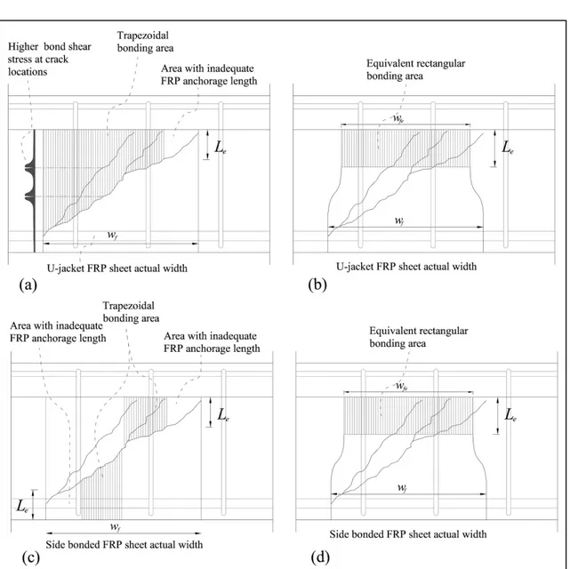
in shear with EB continuous FRP sheet: (a) actual bonding area for U-jacket; (b) equivalent bonding area for U-jacket; (c) actual bonding area for side-bonded FRP; (d) equivalent bonding area for side-bonded FRP……….………65 Figure 3.5 βc= wfe / df ratio versus FRP rigidity plus transverse-steel rigidity for
bonded U-jacket configuration………..……….66 Figure 3.6 βc= wfe / df ratio versus FRP rigidity plus transverse-steel rigidity for
side-bonded configuration………..67 Figure 3.7 Predicted versus experimental FRP contribution for U-jacket and
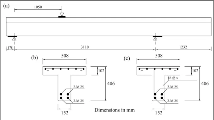
side-bonded FRP calculated using (a) the proposed model, (b) CSA S806, (c) ACI 440 2R, (d) fib TG 9.3, (e) CNR DT-200, and (f) CIDAR……….……….…..69 Figure 4.1 Details of concrete beams: (a) elevation; (b) cross section with no
transverse steel; (c) cross section with transverse steel....…………..80 Figure 4.2 Instrumentation: (a) strain gauges on transverse steel and embedded
in concrete; (b) crack gauges on CFRP sheets and LVDT in mid-span and under loading point; (c) strain gauges on NSM rods; (d) strain gauges on ETS rods and concrete crack gauge…….……..84 Figure 4.3 Cracking pattern of specimen S1-ETS: (a) on the surface (left side
of the picture); (b) on the concrete core (left side of the picture)…...87 Figure 4.4 Common failure mode in beams strengthened with NSM method:
XIII
Figure 4.5 Load versus maximum deflection – Series S1………..….….89 Figure 4.6 Load versus maximum deflection – Series S3.………..….91 Figure 4.7 Load versus maximum deflection – Series S0.……….….….92 Figure 4.8 Load versus maximum strain in FRP – Series S0…………....……...94 Figure 4.9 Load versus maximum strain in FRP – Series S1……….…....……..95 Figure 4.10 Load versus maximum strain in FRP – Series S3………...……96 Figure 4.11 Load versus maximum strain in steel stirrup – Series S1……...…..96 Figure 4.12 Load versus maximum strain in steel stirrup – Series S3…….…..…97 Figure 5.1 FRP rigidity versus shear resistance gain……….106 Figure 5.2 Details of concrete beams: (a) elevation; (b) cross section……..…108 Figure 5.3 Strain gauges on transverse steel and embedded in concrete……...110 Figure 5.4 Load versus maximum deflection – Series S0……….….112 Figure 5.5 Load versus maximum deflection – Series S1………….………...112 Figure 5.6 Failure mode in strengthened beams: (a) S0-0.12R; (b) S0-0.17R1;
(c) S1-0.23R; (d) S10.33R……….…………...…114 Figure 5.7 Load versus maximum strain in FRP – Series S0…………....…….116 Figure 5.8 Load versus maximum strain in FRP – Series S1……….…………116 Figure 5.9 Load versus maximum strain in steel stirrup – Series S1….………117 Figure 5.10 Elevation of: (a) specimen S1-0.17R1 with CFRP strips placed in
the same locations along the longitudinal axis as the steel stirrups; (b) specimen S1-0.17R2 with CFRP placed mid-way between the steel-stirrup locations (dimensions in mm)………...…121 Figure 5.11 Predicted versus experimental FRP contribution: (a)
ACI 440 2R-08; (b) ACI 440 2R-08 multiplied by Holzenkämfper (1994) coefficient; (c) ACI 440 2R-08 multiplied by Brosens
XIV
Figure 5.12 Predicted versus experimental FRP contribution:
(a) ACI 440 2R-08; (b) ACI 440 2R-08 multiplied by Brosens and Van Gemert (1999) coefficient; (c) ACI 440 2R-08 multiplied by Chen and Teng (2001) coefficient…………..………..125 Figure 5.13 Experimental kf (Vf exp / Vf cal)of the test specimens and kf proposed
by Holzenkämfper (1994), Brosens and Van Gemert (1999), Brosens (2001), and Chen and Teng (2001) versus strip-width to strip-spacing ratio………..………..……….……126 Figure 5.14 Experimental kf (Vf exp / Vf cal)from database and kf proposed by
Holzenkämfper (1994), Brosens and Van Gemert (1999), Brosens (2001), and Chen and Teng (2001) versus strip-width to
strip-spacing ratio…..…………..……….……127 Figure 6.1 Cross section of RC T-beams used in the research study….……....139 Figure 6.2 Elevation of specimen S3-EB-SBFA with surface bonded CFRP
laminate end-anchorage system………...…….142 Figure 6.3 Elevation of specimen S3-EB-DAMA; (a) first aluminum plate
installed; (b) second aluminum plate installed……….142 Figure 6.4 Specimen S3-EB-ERBA after the embedded round FRP bar
end-anchorage system is installed………..………..143 Figure 6.5 Specimen S3-EB-EFLA after the embedded FRP laminate is
installed……….…144 Figure 6.6 Strengthened specimens after failure: (a) NA; (b)
EB-SDMA; (c) EB-ERBA; (d) EB-EFLA; (e) NSM; (f) S3-EST………..……….147 Figure 6.7 Load versus maximum deflection: (a) beams strengthened with EB
method (with and without end-anchorage systems and the control beams; (b) beams strengthened with EB, NSM and ETS
methods………...……….…….149 Figure 6.8 Load versus maximum strain in FRP: (a) beams strengthened with
EB method (with and without end-anchorage systems and the control beams; (b) beams strengthened with EB, NSM and ETS
methods……….………151 Figure 6.9 Load versus maximum strain in transverse steel: (a) beams
XV
strengthened with EB method (with and without end-anchorage
systems) and beams strengthened with NSM and ETS methods…..153
Figure 6.10 Distribution of maximum strains in the transverse steel at failure...154
Figure 7.1 Details of concrete beams: (a) cross section with no transverse- steel; (b) cross section with transverse-steel; (c) elevation………..164
Figure 7.2 Load versus maximum deflection: specimens S1-CON, S1-12d130s, S1-12d260s, S1-9d260s, and S1-9d260p……….168
Figure 7.3 Load versus maximum deflection: specimens S0-CON, S1-CON, S3-CON, S0-12d130s, S1-12d130s, and S3-12d130s………...…...169
Figure 7.4 Parallel diagonal shear cracks, specimen S1-9d-260s……….170
Figure 7.5 Parallel diagonal shear cracks, specimen S1-9d-260p………….……171
Figure 7.6 Failure mode of specimen S1-9d260s..……….172
Figure 7.7 Failure mode of specimen S1-9d260p………..172
Figure 7.8 Failure mode of specimen S1-12d130s……….173
Figure 7.9 Failure mode of specimen S3-12d130s……….173
Figure 7.10 Load versus maximum strain in FRP……….…...174
Figure 7.11 Load versus maximum strain in internal transverse-steel…….……176
Figure 7.12 Shear contribution of FRP versus FRP rigidity ratio for specimens S1-9d260s, S1-12d260s, and S1-12d130s……..………..181
Figure 7.13 BPE modified bond stress-slip model………...183
Figure 7.14 Analytical and experimental bond shear-slip relation for ETS FRP rods with plain surface and sand-coated surface epoxy-bonded to a concrete block………...185
Figure 7.15 Predicted versus experimental FRP contribution for RC beam strengthened using the ETS method……….188
LIST OF SYMBOLS
Af Area of the cross-section of an FRP sheet or strip = 2n.tf.wf Afv Area of the cross-section of an FRP sheet or strip = 2n.tf.wf As Area of the cross-section of steel stirrup
b Width of the concrete-beam cross-section bc Width of concrete member
bf, bp Width of bond area
bw Concrete section web width
cf Constant determined using the results of shear tests d Effective depth of the concrete beam
df Distance from the extreme compression fibre to the centroid of tension reinforcement
Df Stress distribution factor
Ef Elastic modulus of FRP in the principal fibre-orientation direction f′c, fck, fcm Cylindrical compressive strength of concrete
fctm Average surface tensile strength of concrete ffd Design value for the ultimate FRP stress ffdd Design value for the FRP debonding stress ffd,mam Maximum design stress in FRP
ffe Effective stress of FRP
ffed Design value for the FRP effective stress ffu Ultimate FRP tensile stress
fct Concrete tensile strength Gfk Bonded joint specific fracture energy
hfe Effective height of the bonded reinforcement hw Concrete cross section web height
k1 Concrete-strength modification factor k2 Wrapping-scheme modification factor kb Covering / scale coefficient
kp Factor related to the width of the bonded plate and the width of the concrete member
L FRP fiber length
Le Effective anchorage length of FRP Lmax Maximum available bond length nf Number of FRP layers
Pbond Bond shear force in the equivalent rectangular area Pfe Effective resisting force in the FRP
Pmax Force that can be developed in the sheet on one side of the beam
Pu Ultimate bond strength rc Corner rounding radius
RL Ratio of FRP effective width to total FRP width R2 Coefficient of determination
R* Reduction factor, a function of EsAs/EfAf sf Spacing between FRP strips
suf FRP slip at debonding (0.20mm) tf Thickness of FRP composite Vc Contribution of concrete to shear
Vf Contribution of FRP to shear as defined in ACI 440 2R-08 and CSA-S806
Vfrp Contribution of FRP to shear as defined in CSA-S06 Vf cal Contribution of FRP to shear as calculated by models Vf exp Experimental contribution of FRP to shear
Vn Nominal shear resistance at the ultimate limit state Vs Contributions of internal steel reinforcement to shear
wf Width of an FRP strip wfe Effective FRP width
α Angle of inclination of the FRP fibres
β Shear-slip coefficient (set equal to 0.315 times the 95th percentile characteristic value of the bond strength proposed by Chen and Teng (2001))
βc Concrete-cracking coefficient based on transverse-steel and FRP rigidity values
βL Coefficient to compensate for insufficient FRP anchorage length βw FRP-width-to-spacing-ratio coefficient
γfd Partial safety factor depending on the application quality γrd Partial factor for the resistance model (1.2)
εfe Effective strain of FRP εfu Maximum strain of FRP
κv Bond-reduction coefficient
λ Normalized maximum bond length θ Angle of concrete shear crack
ρf FRP strengthening ratio = (2n.tf /b).(wf /sf ) ρs Transverse-steel ratio = Av /bw.s ρtot Total shear-reinforcement ratio = n.ρf + ρs τeff Average bond shear stress at failure
INTRODUCTION
A large number of aging civil infrastructures are known to be structurally deficient at the present time. Three decades of delayed maintenance work have created a situation where if the deterioration is not halted, the associated costs will escalate exponentially (Mofidi 2008). Structural deficiencies in bridge girders are usually the result of deterioration caused by ageing, exposure to harsh environments, and higher traffic demands.
During last decades, Fibre-Reinforced Polymers (FRP) have received much attention for a variety of applications in strengthening of defective structures due to their technical and economical advantages. The outstanding mechanical characteristics of FRP combined with its high strength-to-weight ratio, corrosion resistance and easiness of handling and application make the FRP composites a variable strengthening alternative material.
The area of advanced composites in strengthening structures has been one of the fastest growing areas within civil engineering during the decade. Much focus and effort has been placed on understanding the behaviour of the concrete structures strengthened with FRP. Common structural deficiencies of deteriorated bridge girders are their inadequate shear strength or their low flexural and displacement ductility capacities. Strengthening of beams and slabs in flexure and confinement of columns are well documented. However, a review of research studies on shear strengthening reveals that experimental investigations are still needed to encompass T-section beams and joints. Most of the few research studies that have been performed in strengthening RC beams in shear were conducted on rectangular RC sections. The previous tests were mostly conducted on small size beams that may perform differently from Full-scale girder in several aspects. Besides, FRP debonding failure mode that leads to a premature beam failure in a brittle manner is still a disadvantage for the beams strengthened with FRP. This doctorate study is aimed to address these shortcomings.
CHAPTER 1
RESEARCH FOCUS AND OBJECTIVES
1.1 Problem definition
In Quebec and Canada, many of the ageing reinforced concrete (RC) infrastructures suffer from serious degradation of materials. This degradation, which is severe in Quebec's bridges, is due to the effect of steel reinforcement corrosion, the action of freeze-thaw cycles and increased use of de-icing salts. The degradation of the bridges combine with structural deficiencies due to changes in operating loads and more stringent new design codes has created a critical situation for the bridge inventory in Quebec and Canada.
According to Statistics Canada (2012), the useful life of a bridge in Canada is set at 43.3 years. The average age of bridges in Canada is 24.5 years compared to 31 years in Quebec. In addition, 57% and 72% (the highest ratio in the nation) of bridges in Canada and Quebec respectively have exceeded their useful life.
In Quebec and Canada, many girders were designed on the basis of the pre-1970s codes and standards. In fact, about 80 per cent of Quebec roads and bridges were built in the 1950s and 1960s. Several researchers pointed out that previous design provisions did not have a comprehensive understanding of the shear behaviour. As a result, pre-1970s designs might be deficient in shear according to current codes. Such deficient beams, would fail suddenly and without warning, even before the element reaches its full capacity in flexure, once their shear capacity is reached. The collapse of “de la Concorde” overpass in Laval is a tragic example of sudden and without warning shear failure in concrete bridges that led to loss of life and significant economic disruption. In this respect, Mr. Sam Hamad, former Minister of Transportation of Quebec, noted that the “de la Concorde” overpass did not meet the load capacity for modern trucks. So far, there is no statistical data on the number of deficient bridges in shear in Quebec. However, it may be instructive to consider that in the province of
3
Alberta among 5000 bridges that required strengthening, more than 3000 (60%) showed deficiency in shear.
Since the “de la Concorde” overpass collapse, Premier Jean Charest’s government has earmarked $21 billion for infrastructure. Following the incident, 135 bridges and overpasses were inspected in recent months after being identified for potential safety risks. The transport ministry decided to replace 28 bridges and overpasses conduct extensive repairs on 25 more, and reinforce four bridges from the list of 135. Replacing a large number of the deficient bridges at the same time requires enormous Federal and Provincial investments. Rehabilitation of those bridges seems to be a better alternative as it is faster, safer and more economical. According to recently published report on Champlain bridge by Ministère des Transports du Québec (2011), the estimated cost for a new bridge to replace the current Champlain bridge is $1.282 billion. Federal Canadian government issued $5 billion to replace the existing Champlain bridge. Whereas, prolonging the life of the current Champlain Bridge would only cost as much as $25 million a year for the next decade.
Historically, concrete members have been repaired by post-tensioning or jacketing with new concrete in conjunction with a surface adhesive (Klaiber et al. 1987). Since the mid 1960s epoxy-bonded steel plates have been used to retrofit flexural members (Dussek 1980). Steel plates have a durability problem inherent to this technique, because corrosion may occur along the adhesive interface. This type of corrosion adversely affects the bond at the steel plate/concrete interface and is difficult to monitor during routine inspection. Additionally, special equipment is required to install the heavy plates.
Recently FRP composites have been increasingly used in rehabilitation and strengthening of concrete structures. The advantages of using composites are mainly due to their high modulus of elasticity, lightness, corrosion resistance, and adaptable electromagnetic properties. To date, various FRP rehabilitation methods are being applied in practice for strengthening and improvement of RC concrete beams. Although the technique of using FRP in structural rehabilitation has proven its feasibility and viability during the last two decades, more comprehensive research studies in some specific areas are still in need.
4
1.2 Scope of work and objectives
Scope of work
This PhD program deals with the shear strengthening of RC beams using fibre-reinforced FRP composites. Due to its complexity, the shear strengthening of RC members with externally bonded (EB) FRP still has numerous research problems that require further investigation to be completely solved (e.g., accurate analytical models; FRP debonding; effect of transverse steel). Recent findings have highlighted major influencing parameters related to shear strengthening with EB FRP that have still not been captured by existing theoretical predictive tools (e.g., effect of transverse steel among others), including the codes and guidelines. A new design method is proposed in this PhD program to consider the effect of transverse steel in addition to other influencing factors on the shear contribution of FRP. The accuracy of the proposed equations has been verified by predicting the shear strength of experimentally tested RC beams using data collected from the literature. On the other hand, current methods in shear strengthening of RC beams with FRP present shortcomings such as: (i) concrete strata; (ii) surface preparation; (iii) protection (vandalism /fire); (iv) debonding. In this PhD program new shear retrofitting methods has been developed to increase the shear capacity of RC beams. The new methods present many advantages over existing methods such as EB FRP sheet method and near-surface mounted (NSM) FRP rod method. Unlike the current methods where the FRP relies on the concrete cover of RC beams, in the new methods FRP relies on the concrete core of the RC beam which offers a greater confinement and hence improves bonding performance. The proposed methods to prevent FRP debonding in this program are: (1) Embedded through-section (ETS) FRP rods method; (2) New end-anchorage systems for FRP U-jackets. The results of the analytical and experimental research studies reveal that the performance of the beams strengthened using these methods are far more superior to that of the beams strengthened with EB FRP and NSM FRP methods.
The results of this Ph.D program are reported in five published articles in international refereed journal papers and three articles in press.
5
Objectives
The main objective of this program is to study the behaviour of RC beams strengthened with FRP material in shear.
The specific objectives are:
a) to experimentally and analytically study different rehabilitation methods of full-scale RC T-section beams in shear using FRP sheets, strips and rods;
b) to investigate the design procedures in the guidelines to evaluate the shear contribution of EB FRP in the shear resistance of retrofitted RC beams. To review existing design proposals and to highlight their deficiencies;
c) to study the effect of certain parameters which have been proven to influence the shear resistance of EB FRP, but which have not been sufficiently documented in the guidelines (e.g., cracking pattern; FRP anchorage length; FRP strip width to spacing ratio etc.); d) to better understand the interaction between internal transverse steel and external FRP
reinforcement. To realize the effect of the steel and FRP transverse reinforcement on concrete cracking pattern and FRP debonding;
e) to develop a transparent, rational, and evolutionary design model for the shear resistance of FRP-strengthened beams which fail by FRP debonding. It is thought that such a design proposal will offer an improvement to the current debonding design equations in the guidelines;
f) to analyze the behaviour of RC beams strengthened in shear with the ETS FRP rods by varying the influencing parameters;
g) to identify different failure modes in beams strengthened with the ETS method;
h) to study the mechanics of interaction between the concrete and the FRP rod in the RC beams strengthened in shear using the ETS FRP rod method;
6
i) to propose a rational design approach to calculate the shear contribution of FRP for the RC beams strengthened in shear with the ETS method;
j) to study the feasibility and effectiveness of new rehabilitation methods of strengthening beams in shear to prevent FRP debonding;
k) to study the feasibility and practicality of new mechanical end-anchorage systems in FRP U-jackets.
1.3 Research significance
Most of the research activities on the use of FRP in strengthening RC beams were directed to enhancing their flexural capacity. For the few research studies that have been undertaken in strengthening RC beams in shear, most of the researches were conducted on RC rectangular sections (Bousselham and Chaallal 2004). Despite the fact that RC T-section and AASHTO type are the most popular shape of girders used in bridges. Research data on shear strengthening is very limited, and often times produced conflicting conclusions. In addition, such research is often limited to small-size rectangular beams. Experimental research data is not available for large-scale girders deficient in shear and retrofitted with FRP. Moreover, recent findings revealed that major aspects related to shear strengthening of RC beams with EB FRP are still not captured by the existing theoretical predictions (Bousselham and Chaallal 2008).
The results of this Ph.D. program will provide us with a better understanding of the behaviour of shear deficient beams in bridges that will be strengthened with FRP sheets, strips and rods. The effect of various influencing parameters will be considered on the strengthened beams. Moreover, this research consolidates the scientifically progressive position of the research in this innovative area in Québec and Canada. Especially since several companies in Québec and Canada work or commercialize composite materials inside or outside the nation. This study can provide guidance to the structural engineers and
7
companies when using different strengthening methods using FRP composites in future projects.
In the first part of this Ph.D program, a transparent and rational design model for the shear resistance of FRP-strengthened RC beams, the failure of which is by FRP sheet debonding, was proposed. This research was initiated with a comprehensive literature review on the previous research studies in this area. It has been realized that the effect of transverse steel on the shear contribution of FRP for RC beams strengthened in shear with FRP is already established but is not considered by any existing international or national codes or guidelines. In addition, the major factors influencing the shear contribution of EB FRP and the role of these factors in the current design guidelines were collected. Finally, a new design approach for calculating the shear contribution of FRP, taking into consideration the effect of transverse steel on the EB FRP contribution in shear was proposed. The effectiveness of the proposed method was verified using experimental results available in the literature. The accuracy of the proposed model was superior compared to available design codes and guidelines. The results of this research were published in the forms of journal article and conference papers. The mentioned article, “Shear strengthening of RC beams with EB FRP-influencing factors and conceptual debonding model” in published to Journal of Composites for Construction, ASCE, which is one of the most prominent journals that deals with the use of FRP materials in construction.
In the second part of this Ph.D program, a series of exploratory tests on RC beams strengthened in shear using the Embedded Through-Section (ETS) FRP rods were conducted. The effectiveness of the newly developed strengthening method was compared with EB FRP sheet and NSM FRP rod shear strengthening methods. The outcome of the tests were analysed and published in the form of a journal article called, “Embedded through-section FRP rod method for shear strengthening of RC beams: performance and comparison with existing techniques”. The article is also published in the Journal of Composites for Construction, ASCE.
In the third part of this doctorate program, the available equations in current international design codes which consider the effect of strip-width to strip-spacing of FRP strips in RC
8
beam strengthened in shear were critically reviewed. Current equations used in codes and guidelines to consider the effect of strip-width to strip-spacing of FRP strips are proposed based on FRP-to-concrete direct pull-out tests on FRP strips bonded to concrete blocks. The applicability of the mentioned equations for RC beams strengthened in shear with FRP strips was not validated. The results of this study reveals that previous equations do not predict accurate results when the strip-width to strip-spacing ratio is greater than 0.5. More accurate equations were proposed where the effect of strip-width and strip-spacing of FRP strips is taken into account. To check the accuracy of the equations in predicting the contribution of CFRP strips to the shear resistance of beams strengthened with CFRP strips, the results of the experimental part of this study on beams strengthened with CFRP strips were considered. The study showed that the predictions based on the proposed equations were more accurate than those based on the design guidelines. The findings of this research can be incorporated into the codes and standards to better predict the shear contribution of FRP in RC beams strengthened in shear. The outcome of the research was published as a journal article in Journal of Composites for Construction, ASCE. The title of the article is, “Shear strengthening of RC beams with externally bonded FRP composites: effect of strip-width to strip-spacing ratio”.
In the fourth part of this doctorate program, an experimental investigation on the performance of full-scale RC T-girders strengthened in shear using EB FRP U-jackets end-anchored with different systems was conducted. Debonding of FRP, particularly in shear, is a major failure mode when using FRP sheets to strengthen concrete structures. Design code provisions and guidelines related to shear strengthening of RC beams using EB FRP suggest the use of end-anchorage systems to prevent FRP debonding. However, no guidelines are available to design effective end-anchorage systems. The main objective of this study is to evaluate the effectiveness of different end-anchorage systems for RC beams strengthened using EB FRP methods. The results of this study are published in the form of a journal article entitled, “Performance of end-anchorage systems for RC beams strengthened in shear with epoxy-bonded FRP”.
9
At the end of this doctorate program, an analytical and experimental investigation was conducted to better understand the behaviour of RC T-beams strengthened in shear with ETS FRP rods by varying different parameters. The ETS FRP rod method was proven to be a promising method to increase the shear strength of RC beams. The parameters considered were: (i) the effect of the surface coating on the FRP bars; (ii) the effect of internal transverse-steel reinforcement on the FRP shear contribution; (iii) the effect of FRP bar spacing; (iv) the effect of FRP rod diameter; and (v) the efficiency of the embedded through-section FRP rod method. New design equations were proposed to calculate the shear contribution of FRP for beams strengthened using the ETS FRP method. The design equations were validated against results obtained from the experimental part of the research study.
The promising results of this study were shared with the Ministère des Transports du Québec (MTQ) by Prof. Omar Chaallal, Ph.D supervisor, and with the shear sub-committee of Canadian Standard CSA-S806 that he presides. Positive feedbacks were received in all the mentioned cases.
As this method develops, the structural behaviour of RC beams strengthened with the ETS method needs to be thoroughly characterized and the influencing parameters addressed. The new method can be used to rehabilitate the RC beams and bridge girders in a safer, faster and more economical way. Comprehensive analytical and experimental investigations are still required to completely understand the behaviour or RC beams strengthened with the ETS FRP rod method.
1.4 Outline of thesis
The research work in this study is reported in seven chapters. Chapter 1 provides a brief introduction and discusses the objectives and scope of the research work. Chapter 2 provides a literature review of the previous research topics related to the current work. Chapter 3 presents the first published article in this Ph.D program. The article is titled “Shear strengthening of RC beams with EB FRP-influencing factors and conceptual debonding model”. Chapter 4 titled,
10
“Performance of end-anchorage systems for RC beams strengthened in shear with epoxy-bonded FRP”, presents the published article based on the exploratory tests on the RC beams strengthened with the ETS method. Chapter 5 presents the third article published during this Ph.D program. The article is titled “Shear strengthening of RC beams with externally bonded FRP composites: effect of strip-width to strip-spacing ratio”. Chapter 6 titled, “Performance of end-anchorage systems for RC beams strengthened in shear with epoxy-bonded FRP”,
presents the published article based on the experimental tests on the RC beams strengthened with end anchored EB FRP sheets. Chapter 7 presents the fifth article published during this Ph.D program. The article is titled “Experimental tests and design model for RC beams strengthened in shear using the embedded through-section FRP method”. Finally, conclusions and recommendations for future work are provided.
CHAPTER 2
BACKGROUND AND LITERATURE REVIEW
2.1 Utilization of FRP sheets and rods in shear strengthening of reinforced-concrete (RC) beams
Recently researchers paid more attention to the potential applications and benefits of using FRP in retrofitting RC elements. This is due to the attractive characteristics of FRP, such as its high strength to density ratios, corrosion resistance and high fatigue performance. The area of advanced composites in strengthening structures has been one of the fastest growing areas within civil engineering during the last decade. Much focus and effort has been placed on understanding the behaviour of the concrete structures strengthened with FRP. Strengthening of beams and slabs in flexure and confinement of columns have been well documented. However, a review of research studies on shear strengthening reveals that experimental investigations are still needed to encompass T-section beams. Most of the few research studies that have been performed in strengthening RC beams in shear were conducted on rectangular RC sections. The previous tests were mostly conducted on small size beams that may perform differently from full-scale girders in several aspects.
2.2 Externally-bonded (EB) FRP sheets strengthening method
As it was mentioned previously, most of the research activities on the use of FRP in strengthening RC beams were directed to enhancing their flexural capacity. For the few research studies on strengthening RC beams in shear, most of them were conducted on RC rectangular sections. This is not representative of the fact that most RC beams would have a T-section due to the presence of top slab. To date, most of the research conducted on strengthening RC T-beams in shear focused on enhancing the shear strength of the beam by utilizing the contribution of the FRP through bond with the exterior faces of the beam.
12
Different shear strengthening configuration using FRP are categorized as: complete FRP wraps covering the whole cross section (i.e., complete wrapping, valid only for rectangular sections), FRP U-jackets covering the two sides of the tension face (i.e., U-jacketing) and FRP sheets glued only onto the two sides of the beam (i.e., side bonding).
By 2004, the most effective FRP strengthening configuration for T-section beams were proven to be FRP U-Jackets (Bousselham and Chaallal 2004). This section provides a comprehensive review of all the papers related to reported experimental investigations on shear strengthening with externally bonded FRP. The review is presented in a chronological order, to allow a better understanding on the evolution of the findings of the research effort, as well as the issues involved as the research progressed. For each paper, the review provides information on the objectives, the methodology, the experimental program, the test method, the FRP used and its orientation, as well as the strengthening scheme (FRP configuration) used.
Berset (1992)
The first study of shear strengthening with FRP was carried out by Berset (1992). Through a series of tests, he examined the shear behaviour of reinforced concrete beams retrofitted with GFRP composite. Six rectangular beams with dimensions 102 mm × 114 mm × 600 mm were tested, targeting the following two parameters: (i) the thickness of the GFRP composite and (ii) the effect of transverse steel. The GFRP composite fabric used was bonded onto the beam sides at an angle of 45°. The beams with no transverse steel, retrofitted with FRP, failed in shear with debonding of the FRP composite. The gain in shear obtained was a function of the FRP thickness and a 33% to 66% improvement was attained. By contrast, the beams containing transverse steel failed in flexure. The model developed by the author is based on the truss analogy. The maximum FRP strain, which is an important variable in the model, is drawn from these tests. This investigation, recognized by the author as exploratory, showed that the FRP retrofit technique may result in an enhancement of shear resistance. In its conclusions, the author drew attention to the scale effect, particularly for small specimens such as the ones considered in this study.
13
Uji (1992)
Uji (1992) tested eight rectangular concrete beams of dimensions 100 mm × 200 mm × 1300 mm, strengthened with CFRP composite. The investigation targeted the following parameters: (i) the strengthening scheme, i.e., wrapped versus bonded on the sides and (ii) the effect of transverse steel (by studying sections with and without transverse steel reinforcement). The shear ratio (a/d) was fixed at 2.5. The predominant failure mode of the test beams was by debonding of the composite. The latter never reached more than 30% to 50% of its ultimate resistance. The author observed that the FRP strains were greater than those of transverse steel and therefore concluded that the shear capacity is governed by the bonding mechanism at the concrete-FRP interface.
Al Sulaimani et al. (1994)
Al Sulaimani et al. (1994) investigated the behaviour of concrete beams that were pre-cracked before being retrofitted in shear with GFRP. Two series of tests were performed, one series with and the other without additional strengthening with GFRP in flexure. Each series included eight rectangular beams of dimensions 150 mm × 150 mm × 1250 mm and considered the following composite configurations: (a) composite in two forms, strips or continuous fabric and (b) composite bonded on the sides or wrapped in a U-configuration. It was observed that the beams retrofitted with GFRP strips or continuous GFRP fabric without additional strengthening in flexure failed by debonding. The remaining specimens failed in flexure. The cracks developed followed the same crack pattern initiated during the pre-cracking phase. To evaluate the contribution of the composite, the authors considered the average shear stress at the concrete-FRP interface, which was determined to be 1.2 MPa in the case of strips and 0.8 MPa in the case of continuous fabric. The authors concluded that the U-shaped wrap is more effective in preventing debonding.
Chajes et al. (1995)
Chajes et al. (1995) tested twelve T-section beams of dimensions 63 mm × 190 mm, having a span of 1220 mm, with no transverse steel reinforcement. Three types of FRP were used:
14
glass, aramid, and carbon. The FRP fabric was wrapped around the web in a U-shape over the entire beam length, at two different angles (0°and 90°) with respect to the longitudinal axis. In the case of CFRP, two more wrap angles were tested: 45° and 135°. The specimens were subjected to four-point loads with a shear ratio a/d of 2.7. All the specimens failed in shear and no debonding of the FRP was observed in any of the specimens. The shear resistance increased by 60% to 150% and the strain measured at failure was approximately ε = 0.005. The latter observation was used by the authors to evaluate the contribution of FRP to shear resistance. No distinction was made between the different types of FRP fibres or their orientations.
Sato et al. (1996)
Sato et al. (1996) carried out a series of tests on ten rectangular concrete beams of dimensions 200 mm × 300 mm × 2200 mm, retrofitted in shear with CFRP. The following parameters were studied: (i) the influence of the FRP strengthening scheme, i.e., bonded on the sides versus wrapped in a U pattern, and FRP strips versus continuous fabric, and (ii) the influence of the transverse steel reinforcement.
The test results indicated that the specimens with no transverse steel reinforcement failed by debonding of FRP. They also indicated that the gain in resistance due to U-wrapping of FRP is 60% greater compared to FRP bonded onto the sides. In the model presented, the authors refer to the bonding mechanism at the concrete-FRP interface to describe the failure mode by debonding.
Miyauchi et al. (1997)
Miyauchi et al. (1997) presented the results of tests performed on a series of seventeen beams strengthened in shear with CFRP. The specimens had a rectangular section of 125 mm × 200 mm and a span between supports of 1400 mm. The experimental program considered the following parameters: (i) the strengthening scheme (CFRP strips with three different spacings versus continuous fabric with one or two layers) and the FRP ratio, (ii) the content
15
ratio of the transverse steel reinforcement, and (iii) the shear length ratio which varied between 1.0 and 3.0.
On the basis of these tests, the authors concluded that the rate of increase in the strain on CFRP was greater than that of the strain on steel and proposed a relation which describes the observed interaction. To calculate the contribution of FRP to shear resistance, they adopted the truss analogy by applying a reduction factor of 0.507 to the ultimate FRP stress.
It should be noted that only three of the FRP-retrofitted specimens without transverse steel failed in shear. The remaining specimens failed in flexure. Yet the authors developed their calculations on the basis of these latter specimens, which does not appear to be rational.
Taerwe et al. (1997)
Taerwe et al. (1997) present results of tests conducted on a series of seven rectangular concrete beams of dimensions 200 mm × 450 mm × 4000 mm, strengthened in shear with CFRP. The following parameters were targeted: (i) the influence of the strengthening scheme (U-wrap versus full wrap), (ii) the spacing of the strengthening additions, and (iii) the influence of the transverse steel ratio.
The tests showed that all but one of the strengthened specimens failed by debonding. In the specimen that did not fail by debonding, the FRP wrap fractured after crushing of concrete. Gains in capacity of 20% were achieved. The authors concluded that the contribution of FRP to the shear resistance can be calculated using the truss analogy.
Umezu et al. (1997)
Umezu et al. (1997) conducted a large experimental program on the use of FRP for shear strengthening and retrofit. Twenty-six rectangular concrete beams of various dimensions were tested. For all these tests, the shear ratio was kept constant and equal to 3.
Fourteen specimens were retrofitted with aramid (AFRP) and the rest with carbon (CFRP). The full-wrap composite was either continuous or in strip form and was applied over the entire shear length.
16
The authors observed two modes of failure: (i) failure of FRP after crushing of concrete and (ii) simultaneous rupture of FRP and concrete. As observed by the authors, the latter mode tends to occur with small FRP ratio. In addition, on the basis of the observation that the FRP never reached its full capacity, the authors proposed to apply a reduction factor to the tension resistance of FRP before using the truss analogy model. This factor, which represents the ratio of the resistance obtained by tests over the resistance obtained with the truss model, assuming that the full capacity of the FRP is attained, decreased when the FRP ratio increased. A maximum value of 0.4 is suggested by the authors for the reduction factor.
Funakawa et al. (1997)
Funakawa et al. (1997) tested five rectangular concrete beams of dimensions 600 mm × 510 mm × 5060 mm. Three specimens were retrofitted with one, two, or three layers of CFRP fabric full-wrapped over the entire shear length. A fourth specimen was strengthened with AFRP. The last specimen was maintained as control.
The specimens strengthened with one and two layers of FRP failed by fracture of the FRP, whereas with three layers the fracture of the FRP occurred well after rupture of the concrete in compression. From these results, it could be concluded that the FRP contribution to shear resistance increased with the number of FRP layers, and that the combination of aramid and carbon fibres can be effective for enhancing the stiffness of a retrofitted member.
Araki et al. (1997)
Araki et al. (1997) conducted an experimental program on a series of nine rectangular concrete beams of dimensions 200 mm × 400 mm × 3400 mm. They tested two parameters: (i) the FRP ratio and (ii) the type of fibres, i.e., aramid versus carbon. All the strengthened specimens, when tested, reached the maximum load without fracture of the FRP. Specimens showed shear tension failure mode. In this failure mode, the expansion of shear cracks due to the yielding of stirrups caused failure. In all specimens strengthened with the sheets, rupture of sheets could not be observed when the maximum load was achieved. Fracture occurred after failure of the specimen. FRP strain reached approximately two-thirds of the ultimate
17
strain capacity. The load-deflection curves show that after the formation of the first cracks, the smaller the FRP ratio, the greater was the loss of rigidity. To determine the FRP contribution to shear resistance, the authors used the truss analogy by reducing the tensile resistance of the FRP by an estimated factor of 0.60 for carbon and 0.45 for aramid.
Kamiharako et al. (1997)
Kamiharako et al. (1997) presented results of tests carried out on eight rectangular beams. Two series were considered, depending on the dimensions of the specimens: 250 mm × 400 mm × 3000 mm in Series 1, and 400 mm × 600 mm × 3000 mm in Series 2. The parameters studied were: (i) the rigidity of the FRP, which was applied as a full wrap and consisted either of aramid or carbon fibres, (ii) the influence of the resin used; the FRP was applied without resin in two specimens in Series 1, and (iii) specimen size. The beams were tested under three-point loads. The a/d ratio depends on the height of the specimen, since the shear length was kept constant at 1000 mm.
All the tested beams failed in diagonal tension. The gains in capacity due to FRP varied between 31% and 93%, depending on the rigidity of the FRP and the size of the specimens. As for rigidity, the reported values were greater for carbon than for aramid fibres. Regarding specimen size, the reported gains were greater in beams of Series 2 (height = 700 mm) than for beams of Series 1. However, it must be noted that the a/d ratio for Series 1 (2.5) is different from that of Series 2 (1.7). This would certainly influence the behaviour of the beams, particularly in terms of ultimate resistance. Therefore, the conclusions related to specimen size must be used with caution. Finally, concerning the influence of resin, the reported results indicated that the gains in capacity due to FRP are nil when the FRP is applied without resin.
Täljsten et al. (1997)
Täljsten et al. (1997) conducted a series of tests on eight concrete rectangular beams of dimensions 180 mm × 500 mm × 4500 mm. One of the objectives of the program was to study the shear behaviour before and after retrofit with CFRP. To this end, two of the three
18
control specimens were first tested to failure, then retrofitted, and then loaded again. The CFRP composite was applied onto the sides of the beams at an angle of 45°. The second objective was to evaluate three FRP application systems: (i) hand lay-up, (ii) pre-impregnation in combination with vacuum and heat, and (iii) vacuum injection. The distance between the applied loads was varied so as to ensure rupture by shear.
Only three tests out of ten were valid. For example, the specimens which were highly strengthened (two layers of FRP) failed by flexure, which was attributed by the authors to an underestimation of the shear capacity and a resulting under-design of the beams in flexure. The control specimens which were tested to failure before retrofit ruptured by debonding of the FRP at the FRP-concrete interface. The gain in shear resistance reached 100%. In the third beam, fracture of FRP and rupture of concrete occurred simultaneously. Finally, the authors noted that although the hand lay-up method of FRP application was easier and more convenient, the pre-impregnation and vacuum injection systems achieved better quality control.
Chaallal et al. (1998)
Chaallal et al. (1998-a) studied the performance of concrete beams under-designed in shear and retrofitted with CFRP strips bonded onto the sides of the beams. The experimental investigation included a series of eight beams, of rectangular cross section with dimensions 150 mm × 250 mm × 1300 mm. The parameter studied was the angle of orientation of the CFRP strips: 90° versus 135° with respect to the longitudinal axis.
The strengthened specimens failed by debonding of the CFRP strips. The CFRP did not have any effect on the rigidity of the beams in the initial phase of loading. However, their effect became apparent at the formation of the first cracks and increased with increasing applied load. In their conclusions, the authors noted that shear strengthening enhanced not only the shear capacity, but also the overall rigidity of the retrofitted beams, by inhibiting the propagation of cracks.
19
Mitsui et al. (1998)
Mitsui et al. (1998) investigated the influence of the shear length ratio a/d on the shear capacity of concrete beams retrofitted with FRP. They tested six rectangular beams with a cross section of 150 mm × 250 mm, strengthened with a full wrap of CFRP fabric.
Two parameters were examined: (i) the a/d ratio (two values were considered, 1.14 and 1.59) and (ii) the state of the beams. The latter parameter refers to the following three cases: Pre-loaded beam, lightly cracked and then retrofitted beam pre-Pre-loaded to failure, after which the cracks were repaired with epoxy injection before retrofitting of the beam with FRP. Beams strengthened with FRP with no pre-loading: No debonding was observed in any of the specimens. In all the specimens, the FRP fractured as the beam failed. The measured gain in the shear resistance varied between 30% and 80%. The specimens that were lightly pre-cracked and then retrofitted featured two cracking patterns: one corresponds to the cracks which occurred during the first pre-loading prior to the retrofit and the second corresponding to the cracks due to the second loading after the retrofit. It was also concluded that the contribution of FRP to the resistance tends to increase with the shear length ratio a/d.
Triantafillou (1998)
Triantafillou (1998) proposed a model to determine the contribution of FRP to the shear resistance of reinforced concrete beams. The model is based on the truss analogy by adopting the euro-code format. It was obtained by calibration of data collected by the author from the literature and from his own test results. The latter were obtained from a series of tests performed on rectangular concrete beams of dimensions 70 mm × 110 mm × 1000 mm, without transverse steel, strengthened in shear with CFRP strips. Two variables were tested: the FRP thickness and the angle of orientation (90° and 45°) with respect to the longitudinal axis.
In this model, the FRP strain, εFRP, constitutes the main variable. It is deduced, using the truss
analogy, from the measured FRP contribution and then expressed in terms of the axial rigidity of the FRP, ρFRPEFRP. The author noted in particular that the FRP strain decreased as
20
the rigidity increased. He also noted that the gain due to the FRP varies linearly with the rigidity up to an optimum value corresponding to ρFRPEFRP= 0.4 GPa, after which it remains
constant. The author suggested that this threshold be used as a design criterion.
However, the drawback of this model is that it covers two distinct modes of failure: fracture of FRP and debonding. In addition, the model fails to take concrete resistance into consideration (Khalifa et al. 1998).
Khalifa and Nanni (1999)
Khalifa and Nanni (1999) tested a series of twelve concrete rectangular beams of dimensions 150 mm × 305 mm × 3050 mm, strengthened in shear with FRP. The objective of the study was to study the influence of the following parameters: (i) the presence of internal transverse steel reinforcement, (ii) the shear length ratio a/d (at values of 3 and 4), and (iii) the strengthening configuration. This last parameter referred to the following schemes: (a) unidirectional U-shaped strips with two different widths, (b) unidirectional U-shaped continuous fabric, and (c) bidirectional continuous fabric bonded onto the sides of the beam only. The objective of comparing unidirectional with bidirectional FRP was to evaluate the effect of horizontal fibres on the shear resistance of FRP.
The specimens failed in shear by debonding of FRP. Examination of the test results confirmed that the contribution of FRP stabilized beyond a certain level of FRP axial stiffness. In some specimens, a 250% increase in the FRP ratio enhanced the total shear capacity by merely 10%. In the beams with transverse steel, given the applied load, comparison of CFRP strains with corresponding transverse steel strains shows that in presence of CFRP, the steel is less strained. As for the influence of the shear length ratio a/d, only two tests were valid, and these indicated a slight increase in shear capacity as the a/d ratio increased.
Khalifa et al. (1999)
Khalifa et al. (1999) tested nine continuous rectangular beams with a cross section of 150 mm × 305 mm and a span of 2 × 2290 mm, strengthened with CFRP. The parameters of the
21
study included the transverse steel ratio, the FRP ratio, the strengthening configuration, and the orientation of the fibres (unidirectional versus bi-directional).
The modes of failure obtained from the tests were in most cases out of target, since most of the specimens failed by slippage of the longitudinal steel reinforcement or by flexure. Failure by debonding occurred only in two specimens. The latter specimens were both without transverse steel; one was strengthened with a U-shaped CFRP wrap and the other with CFRP strips. However, a significant contribution from CFRP, 83% and 135% respectively, was recorded for these cases. Examination of the load-deflection curves of the two valid tests reveals that the effect of the FRP configuration on the contribution of FRP to the shear resistance became apparent only after a certain level of loading was reached. The U-shaped wrap exhibited better performance in providing rigidity. The authors also introduced a small modification to their model describing the debonding mode of failure, first published in Khalifa et al. (1998), to take into consideration the work by Miller (1999) on the FRP-concrete bonding mechanism. The merit of this study stems from its establishment of the fact that, contrary to the case of simple spans (the majority of tests), the strengthened zones of continuous beams experience maximum shear and maximum moment simultaneously.
Khalifa and Nanni (2000)
Khalifa and Nanni (2000) studied the behaviour of concrete T-beams without transverse steel reinforcement, retrofitted in shear with different configurations of externally-bonded CFRP. Six 150 mm × 405 mm × 3050 mm beams were tested. The strengthened beams failed predominantly by debonding. However, the specimen strengthened with a U-wrap anchored to the compression table by means of an FRP bar failed in flexure. The increase in measured shear capacity was between 35% and 145%. Moreover, the results indicated that the horizontal fibres had no significant effect on the capacity gain, at least in the case of failure by debonding. However, the authors added that such an effect is not to be excluded in the case of deep beams. The following conclusions were drawn from the study: (1) The contribution of FRP to the shear resistance was significant, particularly when adequate anchorage is provided; (2) The U-wrap configuration was more effective compared to FRP bonded onto the sides compared to FRP strips, continuous fabric covered larger areas that