Science Arts & Métiers (SAM)
is an open access repository that collects the work of Arts et Métiers Institute of
Technology researchers and makes it freely available over the web where possible.
This is an author-deposited version published in:
https://sam.ensam.eu
Handle ID: .
http://hdl.handle.net/10985/19271
To cite this version :
Bastien ROCHETON, Frédéric SEGONDS, Floriane LAVERNE, Nicolas PERRY - HESAM: A
Human cEntered Sustainable Additive Manufacturing Tool for Early Design Stages -
Computer-Aided Design and Applications - Vol. 18, n°2, p.258-271 - 2021
Any correspondence concerning this service should be sent to the repository
Administrator :
archiveouverte@ensam.eu
HESAM: A Human cEntered Sustainable Additive Manufacturing
Tool for Early Design Stages
Bastien Rocheton1, Frédéric Segonds1 , Floriane Laverne2 and Nicolas Perry3
1LCPI, Arts et Metiers Institute of Technology, LCPI, HESAM Université, F-75013 Paris, France, frederic.segonds@ensam.eu
2Université Sorbonne Paris Nord, URB2I, UR 4462, F-93000, Bobigny, France, Université de Paris,
F-92049, Montrouge, laverne@univ-paris13.fr
3 Arts et Metiers, CNRS, U.Bordeaux, I2M Bordeaux, F-33405 Talence Cedex, France, nicolas.perry@ensam.eu
Corresponding author: Frédéric Segonds, frederic.segonds@ensam.eu
Abstract. Despite its development over the past several years, Additive
Manufacturing (AM) has not yet unveiled its full potential for sustainable manufacturing. The recent awareness of the environmental impact of products we consume have allowed researchers to lay the first foundations for sustainable AM. Sustainable manufacturing of products necessarily requires reducing the impact of all product life phases, from the early design stages, known as cradle, to grave. In this context, the reduction of the environmental impact of prototypes printed during design phases automatically generates a drastic reduction in the environmental impact of the final product. However, the environmental optimization of prototypes requires an analysis of their uses in order to propose a customized a printing configuration. This paper proposes a method and an associated “Human cEntered Sustainable Additive Manufacturing” (HESAM) tool for early design stages, for sustainable AM (environmental aspect), and the adequacy to the end-user needs related to its prototype. The proposed tool allows to significantly improve the environmental efficiency of rapid prototyping, regardless of the designer's level of competence.
Keywords: Additive Manufacturing, Sustainability, Early Design Stages
1 INTRODUCTION
Each industrial revolution has brought great changes in the way products are manufactured. The next revolution position AM as one of the industry 4.0 pillars [21]. It has to face many challenges, particularly environmental ones [24]. While customers are more and more considering environmental impact of their products [14], it seems crucial to first improve and then optimize sustainable aspects of this technology. Indeed, the environmental impact of AM during the design
phase as a means of representing/testing the concept is often overlooked, even though it represented more than 38% of the use of AM in 2017 [29]. The objective of this paper is to propose a method and an associated “Human cEntered Sustainable Additive Manufacturing” (HESAM) tool for early design stages, focusing on environmentally efficient AM. Designers’ requirements will be taken into account, as well as the influence of the printing parameters of different technologies (colour, mechanical property…).
The Research Question of this paper is: How to optimize the AM of prototypes in a sustainable way? The structure of the paper is as follow: after a State of Art, the method and its development are presented. Finally, the application developed with the method and the user tests are developed and their limitations are explained.
2 STATE OF THE ART
The development of a method for the sustainable optimization of AM during early design phases requires to focus on the potential of AM in terms of sustainable development, the different uses that are made of prototypes.
2.1 Additive Manufacturing and Sustainability
AM was first quantified qualitatively and described as sustainable in 1987 [30]. This quantification was done using a list of 23 criteria covering the following three concepts: economic, social and environmental. However, these criteria have since been considered too general or incomplete even though they have revealed various implications for the durability of AM [6].
Today, environmental consideration is one of the objectives of the industry 4.0 [24]. Companies are led to design products that are more and more environmentally friendly for ethical and commercial reasons in order to satisfy consumer who is increasingly oriented towards well-being and respect for the environment. In order to achieve this objective, new manufacturing processes have to evolve towards sustainable manufacturing, which can be defined as follows: "creation of manufactured products that use processes that minimize environmental impacts, conserve energy and natural resources" [14]. Industry therefore needs to acquire manufacturing facilities such as AM with a greater sustainable potential [5] than current processes. Moreover, AM has many advantages over current subtractive technologies:
• Overall reduction in resources consumption (energy and materials) thanks to the optimization of parts’ shape and weight savings [18].
• Increase in the quantity of recycled materials at the end of the product life [5]
• On demand manufacturing and remanufacturing of parts for maintenance minimizing the use of new parts [5].
• Reduction of the supply chain leading to a reduction in logistics costs [5]
However, the sustainability of AM also implies important links with the expertise of the user in charge of printing the prototype. Indeed, it should be noted that the influence of the user experience is inversely proportional to the environmental impact of the prototype resulting from rapid prototyping [4] This can be explained by incorrect machine settings leading either to overconsumption of materials for a prototype or poor-quality printing requiring the printing of a new part with a different setting.
By analysing different printing configuration for the same prototype, it is mandatory to anticipate its future use and then define adequate printing parameters.
2.2 Rapid Prototyping and Uses
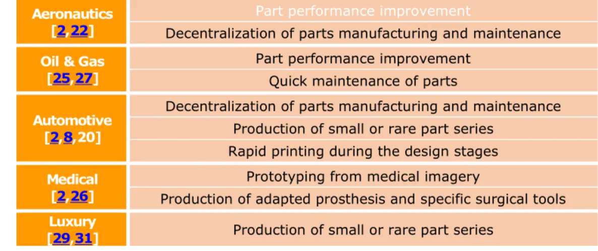
Nowadays, AM is used by many companies covering all the major industrial sectors [29]. In 2017, AM represented a market worth approximately 6.5 billion dollars spread over a dozen sectors. By 2027, the forecasts give a market of 5.4 billion dollars for metal AM [23], essentially divided between the same 12 sectors. Among these sectors, a limited number concentrate most of the market: Aeronautics, Oil & Gas, Automotive and Medical. While others are full of promise as such the Luxury
sector. The study therefore focused on these five main sectors. The interest in AM lies mainly in the freedom given to designers to design and manufacture new products compared to conventional processes. These "AM Unique Capabilities" [7] are classified into four sub-categories: Shape complexity, Hierarchical complexity, Functional complexity and Material complexity. This attraction for AM has led to the development of many uses that vary from one sector to another (Table 1).
Table 1: Main use of AM.
Nevertheless, before producing any final part available on the marketplace, it is necessary to focus on the design phase, which involves the rapid manufacture of many prototypes, mainly for conceptual and functional assessment [15]. Prototypes requirements are usually lower than final part ones (not fully functional or good material for example). Thus, our hypothesis rely on the fact that the quality (shape, roughness, dimension) will be sufficient for the intended use. In fact, the main goal of a prototype is to have a proof of concept and the designer’s attention is focused on the four main “Unique Capabilities” of AM processes [7]. More specifically, the early design stages are crucial as they determine more than 70% of the future product’s environmental impact [19]. A prototype classification has been proposed, based on designer’s expectations [29]:
• Visual aids: Visual model for communication within a team. • Fit: Model allowing to test the shape of a concept.
• Assembly: Model allowing to test the assembly and the size of different parts between them. • Function: Model allowing to test the functioning of the concept in real or no-real conditions
(mechanical tests).
However, the use of prototype differs from one sector to another and can be separated as follows: • Oil & Gas, Aeronautics and Automotive [16,28,29]: Assembly and function.
• Medical [1,3]: Visual aids and function. • Luxury [29,31]: Visual aids and fit.
The distribution of uses according to each sector allows a manufacturing configuration adapted to each sector/use pair. To succeed in such an objective, an analysis of existing methods and tools available that provide adequate print settings is achieved in the next paragraph.
2.3 State-of-the-art Limitations
AM has a real potential to meet the challenges of industry 4.0, particularly for sustainable development. Indeed, this technology allows, while reducing the consumption of raw materials, to design and manufacture prototypes without any physical limits for an extremely large number of
Aeronautics [2,22]
Part performance improvement
Decentralization of parts manufacturing and maintenance
Oil & Gas [25,27]
Part performance improvement Quick maintenance of parts
Automotive [2,8,20]
Decentralization of parts manufacturing and maintenance Production of small or rare part series
Rapid printing during the design stages
Medical [2,26]
Prototyping from medical imagery
Production of adapted prosthesis and specific surgical tools
Luxury
applications. These new design possibilities justify the interest of many sectors for this manufacturing process. However, nearly 56% of AM users do not adapt the printing parameters to the prototypes’ future use [10], which lead to an overconsumption of materials and an increase in the negative environmental impact of the prototype. Some limitations are underlined in current state of the art on the effective transmission of AM knowledge:
• Involvement of AM experts in all projects: the involvement of an expert in each project is difficult to set up [10]
• Creation of a support tool to guide designers print settings: most of the actual tools rely on text documentation that is not easy to use and that require an excellent knowledge of AM processes.
To overcome these limitations, the development of an interactive support tool is proposed. This kind of tool has already proven its effectiveness [9]. The objective of such a tool is to guide users in optimizing their printing strategy in order to get a one shot first good AM prototype, reducing the consumption of materials with the avoided non conform productions. This can only be done through a selection of printing parameters depending on how the user wishes to use the prototype based on the available machines.
3 METHODOLOGICAL PROPOSAL AND ASSOCIATED TOOL 3.1 Method to Optimize Sustainable AM of Prototype
Current environmental optimization strategies in design are always based on the user's choice of technical criteria (Materials, 3D Printer). However, defining and entering information for these criteria may be difficult for users with limited experience in AM. Wishing that the method would include as many users as possible, it was developed along the following two axes:
• User knowledge on AM processes (Beginner or Master). • Industrial sector of the prototype and definition of its use.
The development of a method based on these axes allows it possible to make it optional the inputting technical information by the user in the case of traditional printing.
However, this method must also be able to consider advanced technical information if the user wants particular printing configuration. These methodological choices led to the creation of the method
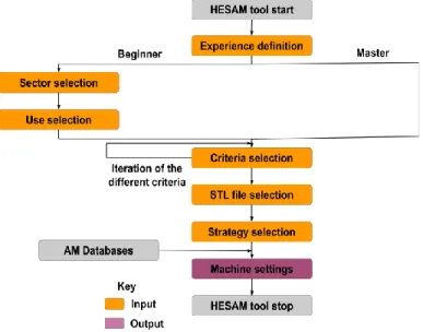
presented in the flowchart in Figure 1, which is called HESAM for "Human cEntered Sustainable Additive Manufacturing method”.
Method Flowchart/Logic: This flowchart can be navigated via two distinct paths depending on the
user's skills that lead to the same final step dedicated to provide the final printing setting based on the user's requirements. The method is explained in the following sub-sections:
1. The user selects his/her skill level with AM. This step enables the user to be directed to the path adapted to his/her level. If the latter does not know how to quantify his/her experience in AM, assistance is provided through questions or criteria related to the user's knowledge and background in AM.
2. The novice user defines the industrial sector of the prototype. This choice allows a pre-selection of uses in the next step. Moreover, as presented in section 2.2, not all sectors are concerned by the four main uses of prototypes.
3. The novice user selects the use of the prototype among the proposed possibilities. The combination of the sector with the use makes it possible to set for possibilities in the next step.
4. In this step technical information about the prototype called "criteria" are selected. A criterion is a technical characteristic related to the selected prototype or printer. On the one hand, the case of the beginner user occurs. No additional information is required because a selection of technical criteria are already made depending on the sector and use provided in the previous steps. The user has only to confirm the selections or modify them if he wants a specifics condition for his/her prototype. On the other hand, the case of the confirmed user occurs. He has to manually enter the level for all the criteria proposed to him/her. As the choice of these criteria is iterative, a control loop check is carried out to ensure that they do not contradict each other and would prevent the development of a printing strategy. 5. In this step, the user provides the STL file of his/her prototype. STL was chosen among
many file formats (VRML, AMF ...) because it has become the standard for 3D printing files [32].
6. The user selects the printing strategy he/she wants to respect. As part of the proposed method, two possibilities can occur: material consumption optimization or cost optimization. The first option proposes a printing strategy that minimizes material consumption (part and support) first and then the cost of the prototype if two AM machines have the same material consumption. The second option reverses these priorities: first cost, then sustainability. 7. This final step provides the design rules to be followed, the AM machine to be used and the
parameter setting to be respected to achieve the objective provided by the pre-selected strategy.
Method Output: After selecting the different manufacturing strategy to be followed, the user will be
able to access the design rules and defined print settings while respecting the data provided during all stages of the method. In a first sub-step, the user will have access to basic design rules in accordance with the machine determined by the method. In a second sub-step, the user will have access to several information which are as follows:
• Reminder of previous entries (sector, use and criteria). • Obtaining the AM machine for use in 3D printing.
• Obtaining the printing parameters to be entered in the AM machine (layer thickness, filling ratio, materials to be used, scale to be respected for the prototype).
• Obtaining the ideal orientation of the prototype.
However, it is accepted that all these parameters may not be respected due to specific constraints of the selected machine independent of its printing capacity (Need to print several different prototypes at the same time...).
3.2 Tool Architecture
The development of a concrete and usable tool based on this method requires a large amount of information, ranging from data on AM technologies to the storage of the various calculation rules used to obtain the printing parameters. However, an associated tool is necessary to ensure the large-scale deployment of the method. In order to master all the data, the application has been designed as a coded web page using Python's Django module (www.djangoproject.com). Selection criteria for this coding environmental are: commonly used, web availability, large choice of coding, manipulation of data bases. This part of the paper will focus on how the different subprograms and databases interact. Section 3.3 and Section 3.4 describe more deeply the content of the tool and its interfaces. The tool architecture can be divided into two main parts as shown in Figure 2. On the one hand, there is the "Management and Calculation programs" section, which concentrates all the application's management and calculation programs. On the other hand, there is the "Database and Interface files" part which manages data related to 3D printers and prototypes but also the source codes of the interfaces.
The interaction and functioning of these two entities can be described as follows:
• The middle set consists essentially of computer programs to control data storage and use in order to get the ideal manufacturing settings. When a request is issued within the interface, it will be processed by different programs that will be able to generate instructions such as sending a new web page, recording new information or calculating new data. This last instruction can be performed by considering new variables entered by the user or present in the databases that constitute the second set of our architecture.
• The right set allows to find the information entered by the designer such as uses, sectors, materials, 3D printers as well as the data provided by the user or obtained by the calculation. Once this data has been provided to the various programs, it will be processed, formatted and integrated into the HTML codes that require it and finally transmitted to the various interfaces.
3.3 Tool Development
The creation of the HESAM method was followed by the development of a digital application of the same name to test it. First, the scope and constraints that the digital tool must respect were defined in order to limit a potential drift from the final application. The main conditions that have been set are as follows:
• Restriction of databases relating to AM machines for those available within the experimental area of LCPI laboratory (Stratasys Connex 260V, Stratasys BST Dimension Elite, MakerBot Replicator 2). All the data handled in one of the 16 databases of the tool are directly linked to the different printing capacity of these machines. The influence of the handled parameters
on the resources’ consumption was carried out experimentally beforehand and allowed the authors creating the models used in the databases [12].
• Development of the HESAM tool with the Django module of Python because it allows to easily modify the application, to integrate many data and allows a diffusion on the Internet. • Integration of simple calculation rules allowing the optimization of printing parameters by
taking into account, if possible, small variations in consumption according to the coupling of the parameters [10].
• Integration of simple and easily processable printing criteria while allowing to have a unique configuration for each prototype (No pre-setting).
Once the characteristics of the application have been defined, each point of the method was developed independently and then integrated into the final tool. To support this strategy, the development of the "Criteria selection" point explained in the following paragraphs can be applied to all the points of the method. A portion of this interface is displayed in Figure 3.
Criteria selection: The development of the "Criteria selection" item was preceded by the creation
of list on technical criteria for 3D printers and materials that influence the final quality of the prototype. The criteria were obtained by analysing the capacity of one-piece printing machines and the materials they use. The list of selected criteria is as follows: Standard AM technologies [11], Building Materials, Surface finish, Filling, Colour, Thermal resistance, Environment resistance and Speed printing. For each of the criteria selected for the application, a predefined response list is proposed based on the characteristics of the printers and materials such as the ability to produce a multicolour prototype (Colour criterion).
Graphical user interface: Once the list of criteria has been set, their formatting within the tool
starts. All criteria are integrated into the application interface with their individual response list. For a question of simplicity, these are put in the form of a question with as answer a choice of image describing each of the possible answers. However, the presentation of all the criteria in the form of a list is not very ergonomic and runs counter to a simple tool. The display of the criteria has therefore been revised and each one has been placed in a window of the dedicated application. Finally, the
answer selected by the user are sent to the management and calculations programs to be analysed and the best printing settings are returned to the result interface.
3.4 Main Functions
In order to have the manufacturing parameters adapted to the prototype’s use, it is necessary to implement some functions within the application. The latter are based on a same operation: input of the variables provided by the user, then calculation and comparison with the information present in the databases, then return of the latter to the user. The main functions of the HESAM tool are as follows:
Printing Orientation: The objective of this first function is to provide the user with the best possible
orientation of the prototype in order to minimize the quantity of support materials. This function can be blocked by the user if the prototype requires a specific printing orientation. It provides approximate but satisfactory results for the tool. and works is as follows:
1. The STL file is selected and the overhang angle that enables manufacturing without support for the considered machine is collected
2. The prototype bounding box is determined using the extreme coordinates on the 3 axes of the triangles composing the STL file.
3. For each reference plane composing the bounding box, a projection of all the triangles is made.
4. For each projection whose normal base triangle in this reference has an angle greater than the limit angle, an intersection search with other projections is performed. The latter are then recorded and classified according to the distance from their original triangle to the projection plane.
5. The closest triangle to the element considered in phase 4 with a smaller projection distance is identified. If there is no matching triangle, the reference plane is selected.
6. The distance between the initial triangle and the element selected in phase 5 is calculated and multiplied by the surface of the initial projection. This allows us to obtain the quantity of support material for this element.
7. For each plan, the quantity of support materials required to print all the triangles is evaluated. The plane with the lowest amount of support material is selected by the application. Finally, the prototype is oriented according to this plan before being visualized by the user.
Printer selection: This function enables to determine all printers suited for the manufacturing. It
can be divided into two parts:
All printer/material couples available in the database are compared with the provided data. All couples that do not fit with one of the constraints is rejected. In the HESAM tool, these criteria are: technology, printing speed, construction material, thermal resistance of the material and resistance to external conditions of the material. The remaining printer/material couples are selected for the second step of the function.
The cost and quantity of building material is calculated for each remaining couple. First, the quantity of support and construction materials required is calculated with 100% filling. Then, these two values are multiplied by unique filling coefficients derived from a correlation of the "Filling" criterion with the data of each registered printer. Then, these two volumes are converted into money thanks to their volume price and these two values are added together. Finally, the printer with the lowest material consumption is selected as part of the designer's choice of the "resource" strategy. The same applies to the cost strategy with the cheapest printing.
Parameters optimisation: This function proposes the best configuration in adequacy with the use
of the prototype. The following printing parameters are considered: Filling density, filling pattern, layer thickness and substrate density. They are called "Parameters optimisation" in the tool:
• Filling density: The user defines the filling he wants for the prototype between three possible choices: empty, medium and full. Each of these values is attached to a filling rate previously defined according to the printing machine.
• Filling pattern: It considers the prototypes’ use, the filling criterion and the possibilities of each machine. For a beginner user, the use has priority over the criteria and is sufficient to define a reason for filling. A Form or Visual Aid use defines a classic hexagonal type filling pattern. A "Fit or Function" use defines a symmetrical filling pattern in all three axes. If no use was proposed, the filling criterion will define the filling pattern, classic for low filling and symmetric for high filling.
• Layer thickness: It is defined by the surface condition desired by the user. The smoother the surface finish, the lower the layer thickness. The notion of thickness will then be modified to be compatible with the possibilities offered by each printing technology.
• Support density: It is independent form the designer's requirements. It is previously defined according to the manufacturing capabilities of each AM technology.
The other parameters available on the different printing technologies are left on the default choice offered by the slicer.
4 USER TESTS
This section presents the user tests conducted on the HESAM tool and their results. The HESAM application is evaluated according to two main axes: its environmental efficiency and its added value during the design phase. The "environmental efficiency" point is evaluated by comparing the material consumption for printing an identical part without and with the HESAM tool for the same user. The objective of this point is to highlight how the application can generate a lower environmental impact for a single machine. The "added value" point in the design phase is evaluated using a form oriented towards the user experience.
4.1 Protocol
Panel: During this test phase, HESAM application is tested by 27 participants from various
backgrounds (engineers, designers and ergonomists). The diversity of the panel allows to represent the different profiles acting during the design phase of a product, which is a multidisciplinary work. All members of this panel are aged from 21 to 37. The panel is then divided into two groups according to their additional manufacturing skills: Beginner and Master. The beginner/master level is based on the use and theoretical knowledge of the user's AM processes.
Case study: Two personas, i.e. fictional characters, created in order to represent the different user
types that could use the tool, (1 for beginners and 1 for masters) and a prototype are developed to simulate a real situation where the use of the HESAM application is necessary. In this scenario, the user is invited to play the role of an engineer with a variable level of qualification in AM (level depending on the user's knowledge). This engineer develops new gear box for a multinational company specialized in the automotive industry. As part of the design of a new product, it is decided to assemble a prototype in order to evaluate its integration into the power transmission chain and its compatibility with the gearbox. The engineer is responsible for printing the last element of this assembly: a gear-shaft responsible for changing the rotation axis orientation (Figure 4). For this prototype, the engineer has a Stratasys BST Dimension Elite printing ABS and he must use the HESAM application for an environmental efficiency development issue.
Process: Each evaluation of the application is conducted individually with the impossibility of
exchanging with any other user by a manager. These evaluations are carried out on a computer with
the necessary programs to run them (Protocol presentation, Stratasys BST Dimension Elite software, HESAM tool). The two experimental panels (Beginner and Master) follow the same evaluation process of the HESAM tool, described in the following steps:
• Step 1: The manager presents the evaluation process to the user using a visual aid. (5min) • Step 2: The user becomes acquainted with the persona and the prototype that must be printed through a presentation. The user has the possibility to visualize the prototype on a CAD software in order to be aware of its geometric constraints. (5min)
• Step 3: The user has at his/her disposal the software of the Stratasys BST Dimension Elite. He/she must propose without the HESAM tool a configuration and printing orientation of the prototype adapted to its use. The manager records these parameters and the material consumption simulated by the software. (10min)
• Step 4: The user enters the information in the HESAM tool that he/she considers realistic regarding the use of the prototype. Then, he/she retrieves the optimized printing parameters that it provides to the Stratasys BST Dimension Elite software. Finally, the manager records new parameters and material consumption simulated by the software. (10min)
• Step 5: The user completes a form provided by the manager in order to assess the added value of the application. (10min)
4.2 Results and Analysis
The main purpose of the results study is to highlight the effectiveness of the HESAM tool by reviewing the variation of 3 variables: model (including support) material consumption and printing time. To do so, a cross-analysis is carried out between the availability of the tool and the AM knowledge level of the panels.
Results: The first part of the results consists of an analysis of the mean values (M) and standard
deviations (SD) of the different variables expressed in cm3 and min (Figure 5). The second part
consists of a more detailed comparison of the consumption of support materials between the different panels using a Mann-Whitney, a non-parametric test commonly used to compare two independent small samples (Table 2).
Analysis: This analysis can be divided into 3 parts as shown in the Figure 5 with the numbered
arrows.
1. Beginner/Master without HESAM tool:
Figure 5: Variation of consumption in cm3 and min. Model material - M=11.78 SD=2.38 Support material) - M=10.10 SD=2.33 Printing time - M=385 SD=102 Model material - M=10.03 SD=0.44 Support material - M=8.60 SD=2.07 Printing time - M=256 SD=77 Model material - M=10.27 SD=0.36 Support material - M=5.70 SD=0.26 Printing time - M=214 SD=56 Model material - M=10.80 SD=1 Support material - M=5.29 SD=0.24 Printing time - M=168 SD=24 Beg in n er Mas te r Without HESAM With HESAM
2
2
1
3
This comparison highlights that the manufacturing of the gear shaft by the master panel requires less model and support material than the one performs by the beginner panel. However, such a difference does not exist for the support material consumption: a Mann-Whitney U test indicates that they can be assimilated to a single panel (p=0,21) with the same median around 9.9 cm3 for the support material. These results can be explained by a
greater knowledge of AM from a technical point of view but a gap when it comes to the simple use of AM. These differences but also similarities call into question the definition of an AM expert as defined. Rather, it should focus on knowledge of the use of AM machines and not on purely technical knowledge.
2. Without/With HESAM for both cases:
In the case of the two separate panels, all values have decreased. The greatest decrease is observed for both panels on the support material which leads to a reduction in printing time. These reductions have two sources: an improbable choice of printing orientation and support manufacturing strategy. The decrease or stagnation of the model material is mainly due to a high filling rate. Standard deviations of the different ones have decreased (from 2.33 cm3
and 2.07 cm3 to 0.24 cm3 and 0.26 cm3 for support) with the use of the application. This
shows that for a given panel and persona, the information provided by the application converges towards the same values.
3. Beginner/Master with HESAM tool:
This comparison shows that the support material consumption in the beginner panel is smaller than the one in the master panel, while model material is similar. This difference mainly results in a shorter printing time coming from a lower manufacturing resolution in the beginner group. The Mann-Whitney U test performed on the support material consumption in the two groups has a p-value equal to 0.03 (Table 2) : it does not allow to confirm that that the two panels can be assimilate to a single sample of users i.e.no difference between the two groups. The rejection of this hypothesis shows that the path taken within the HESAM application has an influence on the final result by the tool. The "master" path proposes too important choice of criteria leading to a divergence from the "beginner" path.
Without HESAM With HESAM
p-value 0.21 0.03
Hypothesis (no difference
between groups) Accepted Rejected
Table 2: Mann-Whitney U test on support material.
As a conclusion, a general reduction in material consumption and printing time are allowed for user by using HESAM tool which demonstrates the usefulness of such a tool guide engineer during its prototype development, and improve the environmental efficiency of AM prototyping activities.
In addition, user comments on their experience of the tool, collected at the end of the test through an individual survey, raised several methodological issues within the application according to three very specific criteria [17]: usability by focusing on learning and satisfaction, utility of the recommendations provided and their acceptability. The master branch which is complex, requires much information and knowledge on machine park that a user does not necessarily have. The beginner branch confronts the user with pre-filled technical criteria while the latter has no knowledge in this field. Following these remarks, it would be appreciated to rename the beginner branch into master branch. Finally, a new beginner branch should be created where users will not have access to the technical criteria or only on their choice.
5 CONCLUSIONS AND PERSPECTIVES
In order to make the rapid prototyping of new products in the design phase more sustainable, this article proposes a new design tool to adapt the printing parameters of their concepts to their usefulness.
The tool previously developed and tested allows the improvement the environmental efficiency of rapid prototyping, regardless of the designer's level of competence. To do so, it generates, following a number of information entered, the selected AM machine, the appropriate configuration and the optimal orientation of the prototype in order to minimize media consumption. The results obtained at the end of the user tests demonstrate the effectiveness of this method and the associated tool since all users, regardless of their level of experience, have reduced their consumption of support material and model. However, the results reveal some problems either in the method developed upstream or in the tool that uses the concept. Indeed, the user tests conducted on the HESAM tool have highlighted a number of interface problems directly related to the method developed. A simplification of the method as mentioned in Section 4.2 in order to make future tools more understandable is necessary. Moreover, the calculation strategies implemented within the application do not allow to cover all the possibilities of prototyping available today. It is necessary to enrich the database of printing parameters and to simplify the calculations, especially in terms of the quantity of support material that can provide incorrect settings under certain conditions. In addition, an extension of the prototyping possibilities within the HESAM tool would significantly increase the use scope of the application.
Future versions of the HESAM tool resulting from this first demonstrator will have to be simplified both from an interface and usage integration point of view but also more complex from a calculation point of view in order to take into account all the possibilities that AM offers today.
Frédéric Segonds, https://orcid.org/0000-0001-5677-4257 Nicolas Perry, https://orcid.org/0000-0003-3215-4867 REFERENCES
[1] Bandyopadhyay, A.; Bose, S.; Suman, D.: 3D printing of biomaterials, Materials Research Society, 40(2), 2015, 108-115. https://doi.org/10.1557/mrs.2015.3
[2] Campbell, I.; Bourell, D.; Gibson, I.: Additive manufacturing: rapid prototyping comes of age, Rapid Prototyping Journal, 18(4), 2012, 255-258.
https://doi.org/10.1108/13552541211231563
[3] Chou, D.-T.; Wells, D.; Hong, D.; Lee, B.; Kuhn H.; Kumta, P. N.; Novel processing of iron-manganese alloy-based biomaterials by inkjet -D printing, Acta Biomaterialia, 9(10), 2013, 8593-8603. https://doi.org/10.1016/j.actbio.2013.04.016
[4] Da Silva Barros, K.; Zwolinski, P.: Influence of the use/user profile in the LCA of 3d printed products, Procedia CIRP, 50, 2016, 318-323. https://doi.org/10.1016/j.procir.2016.05.005
[5] Foteini, M.; Segonds, F.; Rio, M.; Perry, N.: A methodological proposal to link Design with Additive Manufacturing to environmental considerations in the Early Design Stages, International Journal on interactive Design and Manufacturing, 11(4), 2017, 799-812.
https://doi.org/10.1007/s12008-017-0412-1
[6] Gebler, M.; Schoot Uiterkamp, A. J.; Visser, C.: A global sustainability perspective on 3D printing technologies, Energy Policy, 74, 2014, 158-167.
https://doi.org/10.1016/j.enpol.2014.08.033
[7] Gibson, I.; Rosen, D. R.; Stucker,B.: Additive Manufacturing Technologies, Springer, 2010.
https://doi.org/10.1007/978-1-4419-1120-9
[8] Koç, E.; Gökçôl, C.: Additive manufacturing (3D printing) applications in automotive sector, Electronic Journal of Vocational Colleges, 2018.
[9] Laverne, F.; Bottacini, E.; Segonds, F.; Perry, N.; D’Antonio, G.; Chiabert P.: TEAM: A Tool for Eco Additive Manufacturing to optimize environmental impact in early design stages, IFIP
Advances in Information and Communication Technology, 2018, 736–746.
https://doi.org/10.1007/978-3-030-01614-2_67
[10] Laverne, F.; Marquardt, R.; Segonds, F.; Koutiri, I.; Perry, N.: Improving resources consumption of Additive Manufacturing use during early design stages: a case study, International Journal of Sustainable Engineering, 2019.
https://doi.org/10.1080/19397038.2019.1620897
[11] Laverne, F.; Segonds, F.; Dubois, P.: Additive Manufacturing: general principles, Techniques de l’ingénieur, 2018.
[12] Laverne, F., Marquardt, R., Segonds, F., Koutiri, I., & Perry, N. (2019). Improving resources consumption of additive manufacturing use during early design stages: a case study. International Journal of Sustainable Engineering, 12(6), 365-375.
https://doi.org/10.1080/19397038.2019.1620897
[13] Levan, S.L.: Life Cycle Assessment Measuring Environmental Impact, Paper presented at the 49th Annual Meeting of The Forest Prodcust Society, 1995.
[14] Mani, M.; Lyons, K. W.; Gupta, S.K.: Sustainability Characterization for Additive Manufacturing, 119, 2014. https://doi.org/10.6028/jres.119.016
[15] Mellor, S.; Hao L.; Zhang D.: Additive manufacturing: A framework for implementation, International Journal Production Economics, 149, 2014, 194-201.
https://doi.org/10.1016/j.ijpe.2013.07.008
[16] Murr, L. E.; Gaytan, S. M.; Medina, F.; Martinez, E.; Martinez, J. L.; Hernadez, D. H.; Machado, B. I.; Ramirez D. A.; Wicker, R. B.: Characterization of Ti–6Al–4V open cellular foams fabricated by additive manufacturing using electron beam melting, Materials Science and Engineering, 527 (7-8), 2010, 1861-1868. https://doi.org/10.1016/j.msea.2009.11.015
[17] Nielsen, J.: Usability Engineering, San Francisco: Morgan Kaufmann Publishers Inc, 1994 [18] Priarone, P. C.; Ingarao, G.: Toward criteria for sustainable process selection: On the
modelling of pure subtractive versus additive/subtractive integrated manufacturing approaches, Journal of Cleaner Production, 144, 2017, 57-68.
https://doi.org/10.1016/j.jclepro.2016.12.165
[19] Rebitzer,G.; Ekvall, T.; Frischknecht, R.; Hunkeler, D.; Norris, G.; Rydberg, T.; Schmidt, W.-P.; Suh, S.; Weidema, B.W.-P.; Pennington, D.W.: Life cycle assessment Part 1: Framework, goal and scope definition, inventory analysis, and applications, Environmental international, 30, 2004, 701-720. https://doi.org/10.1016/j.envint.2003.11.005
[20] Richardson, M.; Haylock, B.: Designer/Maker : The rise of additive manufacturing, domestic-scale production and the possible implication for the automotive industry, Computer-Aided Design and Applications, 2, 2012, 33-48. https://doi.org/10.3722/cadaps.2012.PACE.33-48
[21] Ruβmann, M.; Lorenz, M.; Gerbert, P.; Waldner, M.; Justus, J.; Engel, P.; Harnisch, M.: Industry 4.0: The Future of Productivity and Growth in Manufacturing Industries, Inovasyon, 2014.
[22] Singamneni, S.; LV, Y.; Hewitt, A.; Chalk, R.; Thomas W.; Jordison, T.: Additive Manufacturing for the Aircraft Industry: A Review, Journal of Aeronautics & Aerospace Engineering, 8(1), 2019. https://doi.org/10.35248/2168-9792.19.8.215
[23] SmarTech Publishing.
[24] Stock, T.; Seliger, G.: Opportunities of Sustainable Manufacturing in Industry 4.0, Procedia CIRP, 40, 2016, 536-541. https://doi.org/10.1016/j.procir.2016.01.129
[25] Trent, J.: 3D Printing in the Oil Field Kicks Into Production Mode, Journal of Petroleum technology, 68(8), 2016, 30-35. https://doi.org/10.2118/0816-0030-JPT
[26] Tuomi, J.; Paloheimo, K.-S.; Vehviläinen, J.; Björkstrand, R.; Salmi, M.; Huotilainen, E.; Kontio, R.; Rouse, S.; Gibson, I.; Mäkitie, A. A.: A Novel Classification and Online Platform for Planning and Documentation of Medical Applications of Additive Manufacturing, Surgical Innovation, 21(6), 2014, 553-559. https://doi.org/10.1177/1553350614524838
[27] Vendra, V.; Achanta, A.: Metal additive manufacturing in the oil and gas industry, in Solid Freeform Fabrication 2018: Proceedings of the 29th Annual International, 2018.
[28] Uhlmann, E.; Kersting, R.; Borsoi Klein, T.; Fernando Cruz, M.; Vicente Borille, A.: Additive manufacturing of titanium alloy for aircraft components, Procedia CIRP, 35, 2015, 55-60.
https://doi.org/10.1016/j.procir.2015.08.061
[29] Wohlers Associates Additive Manufacturing and 3D Printing State of the Industry 2017, 2017. [30] World Commission on Environment and Development, 1987.
[31] Yap, Y.L.; Yeong, W.Y.: Additive manufacture of fashion and jewellery products: a mini review, Virtual and Physical Prototyping, 9(3), 2014, 195-201.
https://doi.org/10.1080/17452759.2014.938993
[32] Yu, K.-M.; Wang, Y.; Wang, C. C.L.: Smooth geometry generation in additive manufacturing file format: problem study and new formulation, 23(1), 2017. https://doi.org/10.1108/RPJ-06-2015-0067